
Related Manuals for Gefen EXT-HDFST-848CPN


Summary of Contents for Gefen EXT-HDFST-848CPN
- Page 1 3GSDI Crosspoint Audio Matrix for Embedder HDMI SOURCES DISPLAYS EXT-HDFST-848CPN User Manual Release A3...
-
Page 2: Important Safety Instructions
8x8 Crosspoint Matrix for HDMI Important Safety Instructions GENERAL SAFETY INFORMATION Read these instructions. Keep these instructions. Heed all warnings. Follow all instructions. Do not use this product near water. Clean only with a dry cloth. Do not block any ventilation openings. Install in accordance with the manufacturer’s instructions. -
Page 3: Warranty Information
Gefen warrants the equipment it manufactures to be free from defects in material and workmanship. If equipment fails because of such defects and Gefen is notified within two (2) years from the date of shipment, Gefen will, at its option, repair or replace the equipment, provided that the equipment has not been subjected to mechanical, electrical, or other abuse or modifications. - Page 4 8x8 Crosspoint Matrix for HDMI is a trademark of Gefen, LLC. Important Notice Gefen, LLC reserves the right to make changes in the hardware, packaging, and any accompanying documentation without prior written notice. HDMI, the HDMI logo, and High-Definition Multimedia Interface are trademarks or registered trademarks of HDMI Licensing in the United States and other countries.
- Page 5 / common resolution be used by all of the source devices. • The Gefen 8x8 Crosspoint Matrix for HDMI is a full-featured crosspoint matrix for eight inputs and eight outputs. Any source can be connected to any display at any time, using the remote control, RS-232, Telnet, or by controlling it via the buttons on the front panel.
-
Page 6: Packing List
HDCP-compliant • Independently routes any eight Hi-Def sources to any of eight HDTV displays • Gefen FST speeds up the HDCP authentication process • Fast and Slow FST switch • Advanced EDID Management for rapid integration of sources and displays •... -
Page 8: Table Of Contents
3GSDI Audio Embedder 8x8 Crosspoint Matrix for HDMI Table of Contents Getting Started Panel Layout ......................2 Front Panel ....................2 Back Panel ....................3 IR Remote Control Unit ..................4 Front ......................4 Back ......................5 Installing the Battery ..................6 Setting the IR Channel .................. - Page 9 8x8 Crosspoint Matrix for HDMI Table of Contents Web Interface ...................... 77 Using the built-in Web Server ..............77 Main ► Routing ..................78 Main ► I/O Status ..................82 Main ► Display Info ..................83 I/O Setup ► Preset Names ................. 84 I/O Setup ►...
-
Page 11: 01 Getting Started
Crosspoint Matrix for HDMI SOURCES DISPLAYS 01 Getting Started Panel Layout ......................2 Front Panel ....................2 Back Panel ....................3 IR Remote Control Unit ..................4 Front ......................4 Back ......................5 Installing the Battery ..................6 Setting the IR Channel .................. 6 Installation ...................... -
Page 12: Panel Layout
Getting Started Panel Layout Front Panel Name Description LCD display Provides feedback of matrix features during operation. Input / Output buttons Used for routing an Input to an Output. Each of these buttons represents an Output. Routing Basics for more information on routing sources. -
Page 13: Back Panel
IP Configuration for more information on RS-232 settings. IR Ext Connect an IR Extender (Gefen part no. EXT-RMT-IREXT) to this jack. Two internal power supplies are included with the matrix. Only one power supply is required to power the matrix. The second power supply is used for redundancy. -
Page 14: Ir Remote Control Unit
Getting Started IR Remote Control Unit Front Name Description Activity indicator This LED glows bright orange when a key is pressed on the remote. Buttons (1 - 8) Used to select the desired input when routing. Buttons (A - H) Used to select the desired output when routing. -
Page 15: Back
Getting Started IR Remote Control Unit Back (shown with cover removed) Name Description DIP switch bank Use these DIP switches to set the IR channel of the remote. See Setting the IR Channel for more information. Primary battery slot Holds the battery for operating the remote. (shown without battery) Use only 3V CR2032-type batteries. -
Page 16: Installing The Battery
Getting Started IR Remote Control Unit Installing the Battery The IR remote control unit ships with two batteries. Only one battery is required for operation. The second battery is a spare. Use only 3V CR2032-type batteries. Remove the back cover the IR Remote Control unit. Insert the included battery into the primary battery slot. -
Page 17: Installation
Sample Wiring Diagram CAT-5 CABLE HDMI CABLE RS-232 CABLE IR Extender Hi-Def Sources Network Matrix IP Control RS-232 Controller HD Displays EXT-HDFST-848CPN WARNING: The power supply should always be connected to a grounded electrical AC outlet. page | 7... -
Page 19: Operating The 8X8 Crosspoint Matrix For Hdmi
Crosspoint Matrix for HDMI SOURCES DISPLAYS 02 Operating the 8x8 Crosspoint Matrix for HDMI Front Panel Controls ................... 10 Powering the Matrix ..................10 Front Panel LCD Screen ................11 Front Panel Buttons ..................12 Routing Basics ....................13 Routing Inputs to Outputs ................13 One-to-One Routing .................. -
Page 20: Front Panel Controls
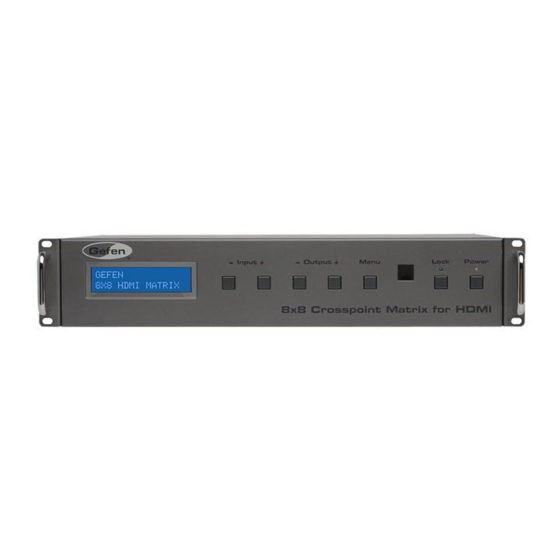
To power-ON the matrix, press the Power button on the front panel. The Power LED will glow bright blue to indicate that the matrix has been turned ON. When the matrix is first powered-ON, the LCD will display the following information: GEFEN 8x8 HDMI MATRIX GEFEN 8x8 HDMI MATRIX After a few moments, the matrix will display the routing status screen. -
Page 21: Front Panel Lcd Screen
Operating the 8x8 Crosspoint Matrix for HDMI Front Panel Controls Front Panel LCD Screen The front-panel of the 8x8 Crosspoint Matrix for HDMI contains a 16-character 2-line LCD display which is used to provide feedback when performing routing functions. In addition, this display is used to show the current routing status of the matrix. -
Page 22: Front Panel Buttons
Operating the 8x8 Crosspoint Matrix for HDMI Front Panel Controls Front Panel Buttons Menu button As described on the previous page, consecutively pressing the Menu button provides a way to cycle through other matrix settings. Of the three screens that can be displayed (routing status, FST mode, and IP address), only the IP address screen cannot be changed using the front panel buttons. -
Page 23: Routing Basics
Operating the 8x8 Crosspoint Matrix for HDMI Routing Basics Routing Inputs to Outputs The following example illustrates the routing process. An input may be routed to a single or multiple outputs. Multiple inputs cannot be routed to a single output. Select the desired output by pressing the Output - or Output + button. - Page 24 Operating the 8x8 Crosspoint Matrix for HDMI Routing Basics Press the Output - button will cycle through each output, from right to left: OUT: Once the output is selected, select the input by pressing the Input - or Input + button. Consecutively pressing the Input + button will increment the input source value by a factor of 1 (within a range of 1 - 8).
-
Page 25: One-To-One Routing
Operating the 8x8 Crosspoint Matrix for HDMI Routing Basics The routing status screen will reflect the new routing state: OUT:ABCDEFGH IN :12335678 OUT:ABCDEFGH IN:12335678 Input 3 is now routed to Output D NOTE: The matrix will automatically return to the routing status screen after about 20 seconds if the Menu button is not pressed. -
Page 26: Locking The Matrix
Operating the 8x8 Crosspoint Matrix for HDMI Locking the Matrix Locking the matrix will prevent any changes by disabling all buttons (except the Lock button) on the front panel. This feature is useful in preventing routing or other changes caused by accidental bumping or pressing of the buttons on the front panel. Press the Lock button on the front panel. -
Page 27: Fast Switching Technology
WITCHING ECHNOLOGY What is Fast Switching Technology? Fast Switching Technology (FST) is a Gefen software implementation for HDMI products. FST was created to improve the lengthy HDMI authentication process, based on the HDMI and HDCP specifications. FST provides quicker audio/video source switching and greatly improves the overall audio/ video system behavior and performance when more than one HDTV display is used in the system setup. -
Page 28: Determining The Current Switching Mode
Operating the 8x8 Crosspoint Matrix for HDMI Fast Switching Technology Determining the Current Switching Mode Each HDMI input can be set to Fast Mode or Slow Mode. It is recommended that each HDMI input be set to Fast Mode for best performance. By default, all inputs are set to Fast Mode. -
Page 29: Changing The Switching Mode
Operating the 8x8 Crosspoint Matrix for HDMI Fast Switching Technology Changing the Switching Mode Changing the switching mode on an input is very similar to the routing method used earlier. Let’s look at an example. Press the Menu button on the front panel until the switching mode screen is displayed. Menu button IN:12345678 MODE:FFFFFFFF... - Page 30 Operating the 8x8 Crosspoint Matrix for HDMI Fast Switching Technology Press the Output - or Output + button again to cycle through each input. Press to move forward through the inputs MODE: Press to move backward through the inputs Pressing the Output + button will cycle through each output, from left to right: MODE: Pressing the Output - button will cycle through each output, from right to left: MODE:...
- Page 31 Operating the 8x8 Crosspoint Matrix for HDMI Fast Switching Technology To complete the switching mode process, press the Menu button on the front panel. IN:12345678 MODE:FFFFFFFF IN:12345678 MODE:FFFSFSSF In the example, above, we also set Input 6 and 7 to slow (S) switching mode. Press the Menu button twice to return to the routing status screen.
-
Page 32: Setting The Ir Channel
Operating the 8x8 Crosspoint Matrix for HDMI Setting the IR Channel In order for the 8x8 Crosspoint Matrix for HDMI to communicate with the included IR remote control unit, both the matrix must be set to the same IR channel as the IR remote. Follow the procedure outlined below to set the IR channel on the 8x8 Crosspoint Matrix for HDMI. -
Page 33: Using The Ir Remote Control
Operating the 8x8 Crosspoint Matrix for HDMI Using the IR Remote Control Routing Sources using the IR Remote Control The included IR Remote Control unit provides discrete routing between each input and output.The IR remote control unit consists of 16 buttons. Each button represents an input / output. - Page 34 Operating the 8x8 Crosspoint Matrix for HDMI Using the IR Remote Control Once again, the LED on the IR remote control unit will flash bright yellow to indicate that a button was pressed. Press button 5 OUT:ABCDEFGH IN:12335678 The front-panel LCD will display the selected input. In addition, the new routing state will immediately be reflected: OUT:ABCDEFGH IN:12535678...
-
Page 35: Edid Management
Operating the 8x8 Crosspoint Matrix for HDMI EDID Management External EDID Management The 8x8 Crosspoint Matrix for HDMI features EDID Management. Before the source can send video or audio signals, the source device reads the EDID (Extended Display Identification Data) from the output devices connected to the 8x8 Crosspoint Matrix for HDMI. -
Page 37: 03 Advanced Operation
Crosspoint Matrix for HDMI SOURCES DISPLAYS 03 Advanced Operation RS-232 and IP Configuration ................28 RS-232 Interface ..................28 RS232 Settings ................... 28 IP / UDP Configuration ................29 RS-232 / IP Commands ..................30 IP / Telnet Configuration ................30 UDP Configuration .................. -
Page 38: Rs-232 And Ip Configuration
Advanced Operation RS-232 and IP Configuration RS-232 Interface DE-9 DA-15 RS-232 Controller Matrix DB-25 Only TXD, RXD, and GND are used. DC-37 RS232 Settings Baud rate ........................19200 Data bits ..........................8 Parity bits ........................None DD-50 Stop bits ..........................1 Flow Control ........................None IMPORTANT: When sending RS-232 commands, a carriage return must be included at the end of the command. -
Page 39: Ip / Udp Configuration
Advanced Operation RS-232 and IP Configuration IP / UDP Configuration The 8x8 Crosspoint Matrix for HDMI supports IP-based control using Telnet, UDP, or the built-in Web-based GUI. To set up IP control, the network settings for the 8x8 Crosspoint Matrix for HDMI must be configured via RS-232. The default network settings for the matrix are as follows: Description IP Address / Port... -
Page 40: Rs-232 / Ip Commands
Advanced Operation RS-232 / IP Commands IP / Telnet Configuration Command Description #display_telnet_welcome Enables / disables the Telnet welcome message #ipconfig Displays the current IP configuration #resetip Resets the IP configuration to factory-default settings #set_http_port Sets the Web server listening port #set_telnet_pass Sets the Telnet password #set_telnet_port... - Page 41 Advanced Operation RS-232 / IP Commands #display_telnet_welcome The #display_telnet_welcome command enables / disables the Telnet welcome message during a Telnet session. The welcome message is: Welcome to EXT-HDFST-848CPN TELNET Syntax: #display_telnet_welcome param1 Parameters: Value [0 ... 1] param1 Value Description...
- Page 42 Advanced Operation RS-232 / IP Commands #ipconfig The #ipconfig command displays the current TCP/IP settings. Also see the #show_ip, #show_netmask, and #show_gateway commands. Syntax: #ipconfig Parameters: None Example: #ipconfig IP Configuration is : IP: 192.168.1.72 NETMASK: 255.255.255.0 GATEWAY: 192.168.1.254 #resetip The #resetip command resets the IP configuration to factory-default settings.
- Page 43 Advanced Operation RS-232 / IP Commands #set_http_port The #set_http_port command specifies the Web server listening port. The matrix must be rebooted after executing this command. The default port setting is 80. The current HTTP listening port can be displayed using the #show_http_port command.
- Page 44 Advanced Operation RS-232 / IP Commands #set_telnet_port The #set_telnet_port command sets the Telnet listening port. The matrix must be rebooted after executing this command. The default port setting is 23. Use the #show_telnet_port command to display the current Telnet listening port. Syntax: #set_telnet_port param1 Parameters:...
- Page 45 Advanced Operation RS-232 / IP Commands #set_webui_op_pass The #set_webui_ad_pass command sets the Operator password for the Web interface. The password cannot exceed 8 characters in length. The default password is Admin. To set the Administrator password, use the #set_webui_ad_pass command. Syntax: #set_webui_op_pass param1 Parameters:...
- Page 46 Advanced Operation RS-232 / IP Commands #show_gateway The #show_gateway command displays the current gateway setting of the matrix. Also see the #ipconfig command. Use the #sgateway command to set the gateway address. Syntax: #show_gateway Parameters: None Example: #show_gateway GATEWAY ADDRESS IS: 192.168.1.1 #show_http_port The #show_http_port command displays the HTTP listening port of the matrix.
- Page 47 Advanced Operation RS-232 / IP Commands #show_ip The #show_ip command displays the current IP address of the matrix. Also see the #ipconfig command. Use the #sipadd command to set the IP address of the matrix. Syntax: #show_ip Parameters: None Example: #show_ip IP ADDRESS IS: 192.168.1.249 #show_mac_addr...
- Page 48 Advanced Operation RS-232 / IP Commands #show_netmask The #show_netmask command displays the current net mask setting of the matrix. Also see the #ipconfig command. Use the #snetmask command to set the gateway address. Syntax: #show_netmask Parameters: None Example: #show_netmask NETMASK ADDRESS IS: 255.255.255.0 #show_telnet_port The #show_telnet_port command displays the Telnet listening port of the matrix.
- Page 49 Advanced Operation RS-232 / IP Commands #show_ver_data The #show_ver_data command displays the current firmware and hardware version. Syntax: #show_ver_data Parameters: None Example: #show_ver_data SOFTWARE AND HARDWARE VERSION: v3.1G PCB-1707*B #sipadd The #sipadd command sets the IP address of the matrix. Use the #show_ip #ipconfig command to display the current IP address of the matrix.
- Page 50 Advanced Operation RS-232 / IP Commands #snetmask The #snetmask command sets the subnet mask. The net mask must be entered using dot-decimal notation. The matrix must be rebooted after executing this command. The default net mask is 255.255.255.0. Use the #show_netmask #ipconfig command to display the current net mask.
- Page 51 Advanced Operation RS-232 / IP Commands #use_telnet_pass The #use_telnet_pass command enables or disables the password when starting a Telnet session. Syntax: #use_telnet_pass param1 Parameters: Value [0 ... 1] param1 Value Description Disable password Enable password Example: #use_telnet_pass 1 Telnet Interface Password Is Enable page | 41...
-
Page 52: Udp Configuration
Advanced Operation RS-232 / IP Commands UDP Configuration Command Description #set_udp_port Sets the local UDP port #set_udp_remote_ip Sets the remote UDP IP address #set_udp_remote_port Sets the remote UDP port #show_udp_port Displays the local UDP server listening port #show_udp_remote_ip Displays the remote UDP IP address #show_udp_remote_port Displays the remote UDP port #use_udp_enable... - Page 53 Advanced Operation RS-232 / IP Commands #set_udp_remote_ip The #set_udp_remote_ip command sets the remote UDP IP address. The IP address must be specified using dot-decimal notation. The default UDP remote IP address is 192.168.1.255. Use the #show_udp_remote_ip command to display the current UDP remote IP address.
- Page 54 Advanced Operation RS-232 / IP Commands #show_udp_port The #show_udp_port command displays the current UDP port. Use the #set_udp_port command to set the local UDP server listening port. Syntax: #show_udp_port Parameters: None Example: #show_udp_port UDP COMMUNICATION PORT IS: 1024 #show_udp_remote_ip The #show_udp_remote_ip command displays the current remote UDP IP address. Use the #set_udp_remote_ip command to set the remote UDP address.
- Page 55 Advanced Operation RS-232 / IP Commands #show_udp_remote_port The #show_udp_remote_port command displays the current remote UDP listening port. Use the #set_udp_remote_port command to set the remote UDP listening port. Syntax: #show_udp_remote_port Parameters: None Example: #show_udp_remote_port REMOTE UDP COMMUNICATION PORT IS: 5500 #use_udp_enable The #use_udp_enable command enables or disables UDP access mode.
-
Page 56: Routing / Naming / +5V / Presets
Advanced Operation RS-232 / IP Commands Routing / Naming / +5V / Presets Command Description #lock_matrix Locks / unlocks the matrix #recall_preset Recalls the specified routing preset #save_preset Save the current routing preset state #set_bank_name Sets the name of the specified EDID bank #set_input_name Sets the name of the specified input #set_output_name... - Page 57 Advanced Operation RS-232 / IP Commands #recall_preset The #recall_preset command restores the specified routing / masking preset. If the specified preset is empty, then Empty Set will be returned. Syntax: #recall_preset param1 Parameters: Preset [1 ... 8] param1 Example: #recall_preset 2 RECALLED THE ROUTING STATE OF PRESET 2 #save_preset The #save_preset command saves the current routing and masking state to a specified...
- Page 58 Advanced Operation RS-232 / IP Commands #set_bank_name The #set_bank_name command names the specified bank. The name of the bank cannot exceed 20 characters in length. Spaces are not permitted when naming outputs. If a space is required, use the underscore (“_”) character. Syntax: #set_bank_name param1 param2 Parameters:...
- Page 59 Advanced Operation RS-232 / IP Commands #set_output_name The #set_output_name command names the specified output. The name of the output cannot exceed 20 characters in length Spaces are not permitted when naming outputs. If a space is required, then use the underscore (“_”) character. Syntax: #set_output_name param1 param2 Parameters:...
- Page 60 Advanced Operation RS-232 / IP Commands #show_bank_name The #show_bank_name command displays the name of the specified bank. Use the #set_bank_name command to set the bank name. Syntax: #show_bank_name param1 Parameters: Bank [1 ... 8] param1 Example: #show_bank_name 4 THE NAME FOR BANK 4 IS: Dell_24 #show_input_name The #show_input_name command displays the name of the specified input.
- Page 61 Advanced Operation RS-232 / IP Commands #show_output_name The #show_output_name command displays the name of the specified output. Syntax: #show_output_name param1 Parameters: param1 Output [A ... H] Example: #show_output_name d THE NAME FOR OUTPUT D IS: Dell_30 #show_preset_name The #show_preset_name command displays the name of the specified preset. Syntax: #show_preset_name param1 Parameters:...
- Page 62 Advanced Operation RS-232 / IP Commands #show_r The #show_r command displays the routing status of the specified output. Syntax: #show_r param1 Parameters: param1 Output [A ... H] Example: #show_r d OUTPUT D(Dell_30) IS ROUTED TO INPUT 5(Blu-ray) The r command routes the specified input to the specified outputs. Up to eight outputs can be specified at a time.
- Page 63 Advanced Operation RS-232 / IP Commands The s command routes the specified inputs to all outputs. Do not precede this command with the “#” symbol. Also see the command on the previous page. Syntax: s param1 Parameters: Input [1 ... 8] param1 Example: INPUT 2 IS SET TO ALL OUTPUTS.
-
Page 64: Status
Advanced Operation RS-232 / IP Commands Status Command Description #help Displays the list of available commands #show_fw Displays the current version of firmware #show_hpd Displays the HPD status of the specified output #show_rsense Displays the RSENSE status of the specified output Displays the current routing status of the matrix Displays the routing state for the specified output #help... - Page 65 None Example: #show_fw FIRMWARE VERSION = EXT-HDFST-848CPN v3.1G #show_hpd The #show_hpd command displays the HPD (Hot-Plug Detect) status of the specified output. If a display (sink) is not connected or if the sink is not powered, then Low will be returned.
- Page 66 Advanced Operation RS-232 / IP Commands #show_rsense The #show_rsense command displays the rsense status of the specified output. Syntax: #show_rsense Parameters: None Example: #show_rsense d RSENSE OF OUTPUT D(Dell_30) IS HIGH #show_hpd The #show_hpd command displays the HPD (Hot-Plug Detect) status of the specified output.
- Page 67 Advanced Operation RS-232 / IP Commands The m command displays the current routing / masking status of the matrix. Do not precede this command with the “#” symbol. Also see the command. Syntax: Parameters: None Example: Out: A B C D E F G H In: 2 2 2 2 2 2 2 2 ALL OUTPUTS ARE UNMASKED MATRIX IS UNLOCKED...
- Page 68 Advanced Operation RS-232 / IP Commands The n command displays the routing state for the specified output. Do not precede this command with the “#” symbol. If param1 = 0, then the routing status for all outputs are displayed. Also see the command.
-
Page 69: Fst
Advanced Operation RS-232 / IP Commands Command Description #fst_fast Sets the specified input(s) to fast-switching mode #fst_slow Sets the specified input(s) to slow-switching mode #show_fst Displays switching mode of the specified input #fst_fast The #fst_fast command sets the specified input to fast-switching mode. If param1 = 0, then all inputs are set to fast-switching mode Syntax: #fst_fast param1... - Page 70 Advanced Operation RS-232 / IP Commands #fst_slow The #fst_slow command sets the specified input to slow-switching mode. If param1 = 0, then all inputs are set to slow-switching mode Syntax: #fst_slow param1 Parameters: Input [1 ... 8] param1 Example: #fst_slow 8 INPUT 8 IS SET TO FST SLOW MODE #fst_slow 0 ALL INPUTS ARE SET TO FST SLOW MODE...
- Page 71 Advanced Operation RS-232 / IP Commands #show_fst The #show_fst command displays the switching mode of the specified input. If param1 = 0, then the switching mode of all inputs will be returned. Syntax: #show_fst param1 Parameters: Input [1 ... 8] param1 Example: #show_fst 8...
-
Page 72: Masking
Advanced Operation RS-232 / IP Commands Masking Command Description #echo Enables / disables RS-232 echo #fadefault Resets matrix to factory-default routing and masking #hdcp Disables / enabled HDCP detection on the specified output #hpd_pulse Cycles with HPD line on the specified output #lock_edid Locks the local EDID during a power-cycle event #mask... - Page 73 Advanced Operation RS-232 / IP Commands #echo The #echo command enables / disables the RS-232 echo. Disabling echo will prevent command feedback from being displayed. Echo is enabled by default. Syntax: #echo Parameters: Value param1 Value Description Disable echo Enable echo Example: #echo 0 LOCAL ECHO IS OFF...
- Page 74 Web UI Operator Password Is Set Web UI Administrator Password Is Set ALL INPUTS HDCP ENABLE. INPUT NAME INIT..OUTPUT NAME INIT..BANK NAME INIT..PRESET NAME INIT..MATRIX WILL REBOOT SHORTLY *REBOOT UNIT IN 2 SECONDS EXT-HDFST-848CPN v3.1G A1B2C3D4E5F6G7H8 page | 64...
- Page 75 Advanced Operation RS-232 / IP Commands #hdcp The #hdcp command disabled HDCP detection on the specified input. NOTE: Some source (computers, etc.) will enable HDCP if an HDCP-compliant display is detected. Set param2 = 1 to ignore detection of an HDCP-compliant display. Disabling this feature does not decrypt HDCP content.
- Page 76 Advanced Operation RS-232 / IP Commands #hpd_pulse The #hpd_pulse command cycles the HPD line on the specified input. This command is the equivalent of performing a physical hot-plug (disconnecting and reconnecting the input cable) on the source device. Syntax: #hpd_pulse param1 Parameters: Input [1 ...
- Page 77 Advanced Operation RS-232 / IP Commands #lock_edid The #lock_edid command locks / unlocks the EDID, stored on all inputs, during a power cycle. By default, EDID data is not locked. Syntax: #lock_edid param1 Parameters: Value param1 Value Description Unlock EDID Lock EDID Example: #lock_edid 1...
- Page 78 Advanced Operation RS-232 / IP Commands #mask The #mask command masks the specified outputs. Multiple outputs can be specified. If param1 = 0, then all outputs will be masked. Use the #unmask command to disable masking on specified outputs. Syntax: #mask param1 Parameters: Output...
- Page 79 Advanced Operation RS-232 / IP Commands #power The #power command is used to power-ON or power-OFF the matrix. Syntax: #power param1 Parameters: param1 Value Value Description Power OFF Power ON Example: #power 0 MATRIX IS OFF #power 1 MATRIX IS ON page | 69...
- Page 80 Advanced Operation RS-232 / IP Commands #reboot The #reboot command reboots the matrix. Syntax: #reboot Parameters: None Example: #reboot MATRIX WILL REBOOT SHORTLY *REBOOT UNIT IN 2 SECONDS EXT-HDFST-848CPN v3.1G A1B2C3D4E5F6G7H8 page | 70...
- Page 81 Advanced Operation RS-232 / IP Commands #set_edid The #seet_edid command sets the specified EDID type for an input or EDID bank. Syntax: #set_edid param1 param2 param3 param4 Parameters: param1 Source type [String] Src. type Description default Uses default EDID dynamic Uses dynamic EDID bank Uses EDID bank...
- Page 82 Advanced Operation RS-232 / IP Commands Notes: If param1 = default or param1 = dynamic, then set param2 = 0. Using Dynamic EDID When param1 = dynamic, the specified input will be set to Dynamic EDID. This can be observed by accessing the Manage EDID tab, in the Web interface. When an input is set to Dynamic EDID, the input will use the EDID of the last selected output during the routing process.
- Page 83 Advanced Operation RS-232 / IP Commands #set_ir The #set_ir command sets the IR channel of the matrix. In order for the included IR remote control unit to function correctly with the matrix, both the matrix and the IR remote must share the same IR channel. See Setting the IR Channel for information on setting the IR channel on the IR remote control unit.
- Page 84 Advanced Operation RS-232 / IP Commands #show_ir The #show_ir command displays the current IR channel of the matrix. Use the #set_ir command to set the IR channel of the matrix. Syntax: #show_ir Parameters: None Example: #show_ir CURRENT IR CHANNEL IS: 2 #show_mask The #show_mask command displays the mask status of the specified output.
- Page 85 Advanced Operation RS-232 / IP Commands #show_out_colordpt The #show_out_colordpt command displays the color depth of the specified output. If no signal is present, NO SIGNAL will be returned. Syntax: #show_out_colordpt param1 Parameters: Output [A ... H] param1 Example: #show_out_colordpt h 8 BITS DVI #show_out_res The #show_out_res command displays the maximum resolution supported by the...
- Page 86 Advanced Operation RS-232 / IP Commands #unmask The #unmask command unmasks the specified output. The #unmask command unmasks the specified output(s). Multiple outputs can be specified. If param1 = 0, then all outputs will be unmasked. Use the #mask command to mask outputs. Syntax: #unmask param1 Parameters:...
-
Page 87: Web Interface
Advanced Operation Web Interface Using the built-in Web Server Access the built-in Web interface by entering the IP address of the matrix that was specified in step 3 on page 29. Once connected to the matrix, the login screen will be displayed. Username Select the username from the drop-down list. -
Page 88: Main ► Routing
Advanced Operation Web Interface The Web interface is divided into four main pages: Main, I/O Setup, Manage EDID, and Configuration. Each of these pages is represented by a tab. Click on the desired tab to open the its page. Each page also has it’s own set of tabs which can be accessed. When the Web interface is opened, the Routing page / tab will be displayed. - Page 89 Advanced Operation Web Interface Lock Matrix Locks / unlocks the matrix. When the matrix is locked, no modifications can be made using the Web GUI. When the matrix is locked, the button text will read “Unlock Matrix” and a red bar will appear across the top portion of the screen with the text “Matrix is LOCKED”.
- Page 90 Advanced Operation Web Interface Name Displays the current name of each output. The name of each output can be #set_output_name changed. Refer to the for details on naming outputs. Output Click to place a check mark in the box and select the desired output. Multiple outputs can be selected at a time.
- Page 91 Advanced Operation Web Interface Log Out Click here to terminate the current Web session are return to the login page. Save Routing Preset Saves the current routing state to memory. Click the drop-down list to select the desired routing preset, then click the Save button to save the preset to memory.
-
Page 92: Main ► I/O Status
Advanced Operation Web Interface Main ► I/O Status Output Displays the state of each output for each of the following: Output name, RSENSE, Mask, HPD (Hot-Plug Detect), and HDCP. Input Displays the following status of each input: Input name, Color Depth, Color Space, HDCP, 3D, Active Signal, Vertical Resolution, Horizontal Resolution, Progressive / Interlaced, and Refresh Rate. -
Page 93: Main ► Display Info
Advanced Operation Web Interface Main ► Display Info Choose EDID Select the EDID from the drop-down list. The selected EDID will be copied from the selected EDID Bank or Output to the desired input(s) and used by the source. Options: Default EDID, Bank 1 ... -
Page 94: I/O Setup ► Preset Names
Advanced Operation Web Interface I/O Setup ► Preset Names Name Type the desired name of the Preset in this field. Click the Save Changes button to save the Preset Name. Click the Cancel button to restore the previous name. Save Changes Cancel Saves the current changes. -
Page 95: I/O Setup ► I/O Names
Advanced Operation Web Interface I/O Setup ► I/O Names Name Type the desired name of each Output or Input in these fields. Click the Save Changes button or click the Cancel button to restore the previous name. Save Changes Saves the current changes. Cancel Cancels the current naming operation. -
Page 96: I/O Setup ► Hpd Control
Advanced Operation Web Interface I/O Setup ► HPD Control Pulse Click the Pulse button to cycle the HPD line on the desired input. This is the equivalent of physically disconnecting and reconnecting the HDMI cable between the source device and the matrix. -
Page 97: I/O Setup ► Fst
Advanced Operation Web Interface I/O Setup ► FST Check All Places a check mark in each box under the FST column. Clear All Clears all check marks from the FST column. Click this button to enable FST on the selected input(s). The Web GUI will display a prompt to verify the selected operation. -
Page 98: I/O Setup ► Hdcp
Advanced Operation Web Interface I/O Setup ► HDCP NOTE: Some computers will enable HDCP if an HDCP-compliant display is detected. Use the Disable feature to force the computer to ignore detection of an HDCP-compliant display. Using the Disable setting does not decrypt HDCP content. Check All Places a check mark in each box under the HDCP column. -
Page 99: Manage Edid ► Assign
Advanced Operation Web Interface Manage EDID ► Assign Lock EDID Secures the Local EDID and disables the automatic loading after power-up. #lock_edid See the command for more information. If the Lock EDID button is clicked (enabled), the “EDID locked on power cycle” message will be displayed in red. - Page 100 Advanced Operation Web Interface Copy To Click to select the desired input(s). Check All EDID Modes Click the drop-down list to select the EDID mode. Places a check mark in each box under the Copy To column. If the EDID Mode is set to Last Output, then the Clear All EDID source will be set to Dynamic EDID.
- Page 101 Advanced Operation Web Interface Check All Copy Places a check mark in each box Click this button to copy the specified under the Copy To column. EDID to the selected inputs / banks. Clear All Cancel Clears all check marks from the Restores the previous EDID state for Copy To column.
-
Page 102: Manage Edid ► Bank Names
Advanced Operation Web Interface Manage EDID ► Bank Names Bank # Indicates the EDID bank number. Name Type the desired name of the EDID bank in this field. Click the Save Changes button to save the bank name. Click the Cancel button to restore the previous name. Save Changes Cancel Saves the current name... -
Page 103: Manage Edid ► Upload / Download
Advanced Operation Web Interface Manage EDID ► Upload / Download Upload Click this button to upload the EDID to the specified bank. Select Bank Location Click this drop-down list to select the bank Browse... to where the EDID will be uploaded. Click this button to select the EDID file to Options:... -
Page 104: Configuration ► Change Ip Settings
Advanced Operation Web Interface Configuration ► Change IP Settings Change IP Settings Assigns the IP address, subnet, gateway, HTTP listening port, Telnet port, and UDP port. The MAC address cannot be changed. Save Settings Saves the current settings for the Change IP Settings. After clicking this button, the Web interface will display a dialog indicating that the matrix must be rebooted for changes to take effect. -
Page 105: Configuration ► Telnet Login Settings
Advanced Operation Web Interface Configuration ► Telnet Login Settings Old Password Type the current (old) password in this field. The factory-default password is Admin. New Password Type the new password in this field. Force Password on Connect Click this check box to have the matrix prompt for a password each time a Telnet session is started. -
Page 106: Configuration ► Udp Connection Settings
Advanced Operation Web Interface Configuration ► UDP Connection Settings Remote UDP IP Address Type the remote UDP IP address in this text box. Remote UDP Port Enter the remote UDP port in this text box. Enable UDP Access Check this box to enable UDP access. If this box is unchecked, the UDP access will be unavailable. -
Page 107: Configuration ► Web Login Settings
Advanced Operation Web Interface Configuration ► Web Login Settings Username Click this drop-down list to select the username to be changed. Old Password Type the current (old) password in this field. The factory-default password is Admin. New Password Type the new password in this field. Confirm Password Re-type the new password in this field. -
Page 108: Configuration ► System Configuration
Advanced Operation Web Interface Configuration ► System Configuration NOTE: As of this writing, the firmware update procedure is not functional from within the Web interface. This feature will be available in a future release of the product. The firmware update procedure must be performed using RS-232. - Page 109 Advanced Operation Web Interface Browse Click this button to select the firmware file to be uploaded. See page 102 for details on updating the firmware. Browse Click this button to select the saved configuration file to be loaded into memory. Restore Uploads the selected configuration file to the matrix.
-
Page 111: 04 Appendix
Crosspoint Matrix for HDMI SOURCES DISPLAYS 04 Appendix Firmware Upgrade Procedure ................102 Specifications ....................104... -
Page 112: Firmware Upgrade Procedure
Go to the Configuration tab in the Web GUI and click the Firmware Update Browse... button under the System Configuration section (see opposite page). Select the firmware file (e.g. EXT-HDFST-848CPN.bin) and click the Update button. The matrix will prompt you to verify that you want to overwrite the current firmware. - Page 113 Appendix Firmware Upgrade Procedure After the matrix has completed successfully, the matrix will reboot and the following will be displayed within the terminal program (if used): EXT-HDFST-848CPN v3.1G A1B4C4D4E5F6G7H8 BANK NAME INIT..PRESET NAME INIT..EXT-HDFST-848CPN v3.1G A1B4C4D4E5F6G7H8 10. Once the routing status screen is displayed, the matrix will be ready to use.
-
Page 114: Specifications
Appendix Specifications Supported Formats Resolution (max.) • 1080p Full HD Electrical Maximum Pixel Clock • 225 MHz Power Indicator • LED, blue = ON; red = standby mode Lock Indicator • LED, blue Connectors Video Input • 8 x HDMI Type A 19-pin, female, locking Video Output •... - Page 116 Stretch it, Switch it, Split it, Control it. Gefen’s got it. ® 20600 Nordhoff St., Chatsworth CA 91311 1-800-545-6900 818-772-9100 fax: 818-772-9120 www.gefen.com support@gefen.com This product uses UL or CE listed power supplies.
Need help?
Do you have a question about the EXT-HDFST-848CPN and is the answer not in the manual?
Questions and answers