Advertisement
Advertisement
Table of Contents

Related Manuals for Gefen 1x8 DVI DA


Summary of Contents for Gefen 1x8 DVI DA
- Page 1 1x8 DVI DA U S E R M A N U A L www.gefen.com...
- Page 2 Notice Gefen Inc. reserves the right to make changes in the hard ware, packaging and any accompanying doc u men ta tion without prior written notice. 1x8 DVI DA is a trademark of Gefen Inc. © 2007 Gefen Inc., All Rights Reserved...
-
Page 3: Table Of Contents
TABLE OF CONTENTS Introduction Features Panel Descriptions Connecting and Operating the 1x8 DVI DA EDID Management Feature EDID Management Modes Specifi cations Warranty... -
Page 4: Introduction
The Gefen 1x8 DVI DA allows one HDTV DVI device to be distributed easily in to eight HDTV DVI compatible monitors or projectors. Simply connect your HDTV displays to the DA’s display outputs. The 1x8 DVI DA can also be placed at the end of a long DVI cable to regenerate the DVI signal. -
Page 5: Features
• Supports HDCP compliant devices • DVI or DVI to HDMI cables are used to connect the inputs and switcher output • Installs in seconds Includes: (1) 1x8 DVI DA (1) 6’ DVI cables (M-M) (1) 24VDC Power Supply (1) Rack Ears... -
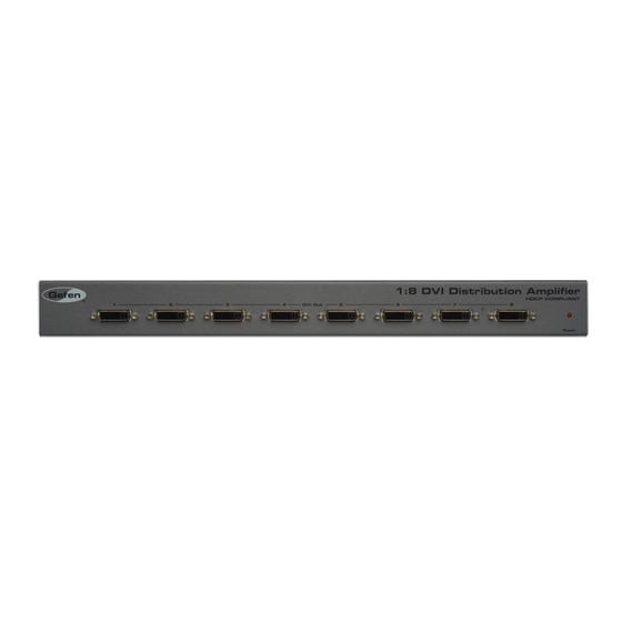
Page 6: Panel Descriptions
PANEL DESCRIPTIONS... -
Page 7: Connecting And Operating The 1X8 Dvi Da
CONNECTING AND OPERATING THE 1X8 DVI DA How to Connect the 1x8 DVI DA to your devices 1 Connect the supplied cable from the HDTV DVI source into the 1x8 DVI DA input. 2 Connect the cables from your displays (monitor or projector) into the DVI outs of the 1x8 DVI DA. -
Page 8: Edid Management Feature
EDID MANAGEMENT FEATURE EDID. What is it and what is it used for? Under normal circumstances, an source device (digital and analog) will require information about a connected device/display to assess what resolutions and features are available. The source can then cater its output to send only resolutions and features that are compatible with the attached device/display. -
Page 9: Edid Management Modes
EDID MANAGEMENT MODES v. 2015d EDID Modes The diagram below illustrates the 8 DIP switch bank. DIP SWITCH Function EDID Mode EDID Mode EDID Mode EDID Mode Use DIP switches 1, 2, 5, and 7 to select the desired EDID management mode. EDID Mode 0 (Switch 1=OFF Switch2=OFF Switch5=ON) •... -
Page 10: Specifi Cations
SPECIFICATIONS Video Amplifi er Bandwidth ..................1.65 GHz Input Video Signal ..................1.2 volts p-p Input DDC Signal ..................5 volts p-p (TTL) Single Link Range ................1080p / 1920 x 1200 Input Connector Type ................DVI (Digital Only) Output Connector Type ................DVI (Digital Only) Power Consumption .................60 Watts (max.) Power Supply ....................12-24VDC Dimensions ..................17”W x 1.75”H x 7.25”D...
Need help?
Do you have a question about the 1x8 DVI DA and is the answer not in the manual?
Questions and answers