Sign In
Upload
Manuals
Brands
YOKOGAWA Manuals
Controller
UT75A
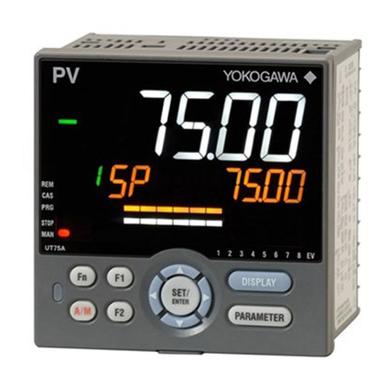
YOKOGAWA UT75A Manuals
Manuals and User Guides for YOKOGAWA UT75A. We have
1
YOKOGAWA UT75A manual available for free PDF download: User Manual
YOKOGAWA UT75A User Manual (498 pages)
Digital Indicating
Brand:
YOKOGAWA
| Category:
Controller
| Size: 22 MB
Table of Contents
Introduction
4
Notice
5
Safety Precautions
5
Contents
5
Handling Precautions for the Main Unit
7
Checking the Contents of the Package
8
Symbols Used in this Manual
11
How to Use this Manual
12
Table of Contents
14
Target Readers
5
Trademarks
5
Chapter 1 Introduction to Functions
22
Quick Setting Function
22
Input/Output Function
23
Control Functions
25
Program Pattern Functions
29
Display and Key Functions
30
Ladder Sequence Function
31
Communication Functions
32
Definition of Main Symbols and Terms
36
Chapter 2 UT75A Operating Procedures
38
Chapter 3 Part Names
40
Names and Functions of Display Parts
40
Names and Functions of Keys
43
List of Display Symbols
46
Brief Description of Setting Details (Parameters)
48
Chapter 4 Basic Operation
50
Overview of Display Switch and Operation Keys
50
How to Set Parameters
53
Chapter 5 Quick Setting Function
58
Setting Using Quick Setting Function
58
Restarting Quick Setting Function
63
Chapter 6 Monitoring And Control Of Regular Operations
64
Monitoring and Control of Operation Displays
64
Operation Display Transitions in Single-Loop Control, Cascade Primary-Loop Control, Cascade Secondary-Loop Control, Loop Control for Backup, and Loop Control with PV-Hold Function
64
Standard Type
64
Position Proportional Type
65
Heating/Cooling Control
66
Single-Loop Two-Position Two-Level Control
67
Operation Display Transitions in Loop Control with PV Switching and Loop Control with PV Auto-Selector
68
Standard Type
68
Position Proportional Type
69
Heating/Cooling Control
70
Operation Display Transitions in Cascade Control
71
Standard Type
71
Position Proportional Type
73
Heating/Cooling Control
75
Operation Display Transitions in Dual-Loop Control
77
Dual-Loop Control (Loop-1)
77
Dual-Loop Control (Loop-2)
78
Heating/Cooling Control
79
Setting Target Setpoint
86
Operation in the Operation Display
86
Operation in Parameter Setting Display
87
Performing and Canceling Auto-Tuning
88
Adjusting PID Manually
91
Setting Alarm Setpoint
97
Selecting Target Setpoint Number (SPNO)
98
Switching Operation Modes
99
Switching between AUTO and man
99
Direct Operation by A/M Key
99
Switching between cas (Cascade), AUTO, and man
101
Switching between STOP and RUN
103
Switching between REM (Remote) and LCL (Local)
106
Switching between P.RUN (Start of Program Pattern Operation) and P.STOP (Stop of Program Pattern Operation)
107
Enabling/Disabling Hold-Mode (HOLD) of Program Operation
109
Executing Advance (ADV) Function
110
Manipulating Control Output During Manual Operation
111
Releasing On-State (Latch) of Alarm Output
113
Chapter 7 Input (Pv, Remote, And Auxiliary Analog) Functions
114
Setting Functions of PV Input, Remote Input, and Auxiliary Analog Input
114
Setting Input Type, Unit, Range, Scale, and Decimal Point Position
114
Setting Burnout Detection for Input
118
Setting Reference Junction Compensation (RJC) or External Reference
119
Junction Compensation (ERJC)
119
Correcting Input Value
120
Setting Bias and Filter
120
Setting Square Root Extraction and Low Signal Cutoff Point
122
Setting 10-Segment/20-Segment Linearizer
123
Setting Ratio Bias/Filter
126
Setting Input Sampling Period (Control Period)
127
Using 4-Wire RTD as PV Input
128
Using Larger, Smaller, Average, or Difference of Two to Four Inputs as PV
129
Setting Remote Input Method
130
Adjusting PV Range for Loop Control with PV Switching or Loop Control with PV Auto-Selector
131
Setting PV Switching Methods of Loop Control with PV Switching
132
Chapter 8 Control Functions
136
Setting Control Mode (CTLM)
136
Single-Loop Control, Single-Loop Heating/Cooling Control, Single-Loop Position Proportional Control, and Single-Loop Two-Position Two-Level Control
136
Single-Loop Control Function Block Diagram
137
Single-Loop Heating/Cooling Control Function Block Diagram
139
Single-Loop Position Proportional Control Function Block Diagram
141
Single-Loop Two-Position Two-Level Control Function Block Diagram
143
Cascade Primary-Loop Control
146
Cascade Primary-Loop Control Function Block Diagram
147
Cascade Secondary-Loop Control, Cascade Secondary-Loop Heating/Cooling Control, and Cascade Secondary-Loop Position Proportional Control
150
Cascade Secondary-Loop Control Function Block Diagram
151
Cascade Secondary-Loop Heating/Cooling Control Function Block Diagram
153
Cascade Secondary-Loop Position Proportional Control Function Block Diagram
155
Cascade Control, Cascade Heating/Cooling Control, and Cascade Position Proportional Control
158
Cascade Control Function Block Diagram
159
Cascade Heating/Cooling Control Function Block Diagram
161
Cascade Position Proportional Control Function Block Diagram
163
Loop Control for Backup, Heating/Cooling Loop Control for Backup, and Position Proportional Loop Control for Backup
166
Loop Control for Backup Function Block Diagram
167
Heating/Cooling Loop Control for Backup Function Block Diagram
169
Position Proportional Loop Control for Backup Function Block Diagram
171
Loop Control with PV Switching, Heating/Cooling Loop Control with PV Switching, and Position Proportional Loop Control with PV Switching
174
Loop Control with PV Switching Function Block Diagram
175
Heating/Cooling Loop Control with PV Switching Function Block Diagram
177
Position Proportional Loop Control with PV Switching Function Block Diagram
179
Loop Control with PV Auto-Selector, Heating/Cooling Loop Control with PV Auto-Selector, and Position Proportional Loop Control with PV Auto-Selector
182
Loop Control with PV Auto-Selector (2 Inputs) Function Block Diagram
183
Heating/Cooling Loop Control with PV Auto-Selector (2 Inputs) Function Block Diagram
185
Position Proportional Loop Control with PV Auto-Selector (2 Inputs) Function Block Diagram
187
Loop Control with PV Auto-Selector (4 Inputs) Function Block Diagram
189
Heating/Cooling Loop Control with PV Auto-Selector (4 Inputs) Function Block Diagram
191
Position Proportional Loop Control with PV Auto-Selector (4 Inputs) Function Block Diagram
193
Loop Control with PV-Hold Function, Heating/Cooling Loop Control with PV-Hold Function, and Position Proportional Loop Control with PV-Hold Function
196
Loop Control with PV-Hold Function Function Block Diagram
197
Heating/Cooling Loop Control with PV-Hold Function Function Block Diagram
199
Position Proportional Loop Control with PV-Hold Function Function Block Diagram
201
Dual-Loop Control and Dual-Loop Heating/Cooling Control
204
Dual-Loop Control Function Block Diagram
205
Dual-Loop Heating/Cooling Control Function Block Diagram
207
Setting Control Type (CNT)
209
PID Control
210
ON/OFF Control (1 Point of Hysteresis / 2 Points of Hysteresis)
211
Heating/Cooling Control
213
Two-Position Two-Level Control
219
PD Control (Stable Control in Which a Setpoint Is Not Exceeded)
221
Sample PI Control (Controlling a Process with Long Dead Time)
222
Batch PID Control (Performing Control with Rapidly Settling Setpoints)
224
Feedforward Control
226
Setting PID Control Mode (ALG)
228
Switching PID
230
Switching PID According to Target Setpoint Number (SPNO)
230
Switching PID According to PV
232
Switching PID According to SP
234
Switching PID According to Target SP
236
Switching PID According to Deviation (Reference Deviation)
238
Setting Hysteresis at Time of PID Switch
239
Switching PID by Contact Input
239
Suppressing Overshoot (Super Function)
240
Suppressing Hunting (Super2 Function)
242
Suppressing Integral Action (Anti-Reset Wind-Up)
244
Performing Non-Linear PID Control
245
Adjusting Auto-Tuning Operation
246
Setting SP Limiter
247
Changing SP at a Fixed Rate (SP Ramp-Rate Setting Function)
248
Forcing SP to Track PV (PV Tracking)
250
Forcing SP to Track Remote Input (SP Tracking)
251
Setting Controller Action at Power on (Restart Mode)
252
Setting Time between Powering on Controller and Starting Control (Restart Timer)
253
Chapter 9 Program Pattern Functions
254
Setting the Program Pattern
254
Setting Conditions
254
Setting the Program Pattern Action Type
254
Setting the Program Pattern Using the Segment Time
256
PID Selection Method
257
Segment PID Selection
257
Zone PID Selection
257
Setting the Program Starting Conditions (STC)
258
Starting Operation at Starting Target Setpoint (SSP) (STC=SSP)
258
Ramp-Prioritized PV Start (STC=RAMP)
259
Time-Prioritized PV Start (STC=TIME)
263
Setting the Wait Functions
264
Program Wait at Segment End
264
Setting the Segment Repetition (Repeat Actions)
266
Setting the Segment End Condition
267
Switching for Continuation (JC=CONT)
267
Hold-On Switching (JC=HOLD)
268
Program Pattern End Signal
269
Chapter 10 Output (Control and Retransmission) Functions
270
Setting Control Output Type
270
Setting Control Output Cycle Time
274
Setting Limiter to Control Output
275
Disabling Output Limiter in man Mode
276
Setting Velocity Limiter to Control Output
277
Reducing 4-20 Ma Current Output to 0 Ma (Tight Shut Function)
278
Setting ON/OFF Control Hysteresis
279
Canceling Offset of PV and SP (Manual Reset)
281
Setting Hysteresis and Dead Band for Heating/Cooling Control Output
282
Setting Hysteresis and Dead Band for Position Proportional Control Output
284
Setting Retransmission Output Terminal, Type, and Scales
285
Setting Preset Output Value
288
Setting Output Value in STOP Mode (Preset Output)
288
Setting Output Value When Switched to man Mode (Manual Preset Output)
290
Setting Output Value When Error Occurs (Input Error Preset Output)
292
Setting 10-Segment Linearizer For Output
293
Changing Current Output Range
295
Setting Split Computation Output Function
296
Adjusting Motor-Operated Valve Position (Position Proportional Output)
298
Setting Valve Operation Mode
299
Adjusting Valve Position Automatically
299
Adjusting Valve Position Manually
300
Setting Valve Traveling Time (Estimating Type)
301
Selecting Feedback Input (Resistor/Current)
301
Using 15 V DC Loop Power Supply
302
Chapter 11 Alarm Functions
304
Setting Alarm Type
304
Setting Number of Alarm Groups to Use
318
Setting Hysteresis to Alarm Operation
319
Delaying Alarm Output (Alarm Delay Timer)
320
Setting Alarm Output to Control Relay Terminal
321
Setting Alarm Action According to Operation Mode
322
Chapter 12 Contact Input/Output Functions
324
Setting Contact Input Function
324
Setting Contact Input Function
333
Changing Contact Type of Contact Input
335
Setting Contact Output Function
336
Setting Function of Contact Output
336
Changing Contact Type of Contact Output
342
Chapter 13 Display, Key, And Security Functions
344
Setting Display Functions
344
Setting Active Color PV Display Function
344
Masking Arbitrary Display Value in Operation Display
347
Changing Event Display
349
Registering SELECT Parameter Display (up to 10 Displays)
351
Setting Bar-Graph Display Function
353
Masking Least Significant Digit of PV Display
355
Changing Deviation Display Lamp Action
356
Setting Economy Mode
357
Selecting the Initial Operation Display that Appears at Power on
358
Setting Message Function
359
Switching Guide Display Language
359
Changing Guide Scroll Speed
360
Turning Guide Display ON/OFF
360
Setting Automatic Return to Operation Display
360
Setting Brightness And Contrast Adjustment Of Lcd And Display Update Cycle
361
Assigning Function to User Function Key and A/M Key
362
Setting Security Functions
365
Setting/Clearing the Password
365
Setting Parameter Display Level
365
Locking (Hiding) Parameter Menu Display
366
Key Lock
368
Setting Display/Non-Display of Operation Display
368
Prohibiting Writing Via Communication
369
Confirmation of Key and I/O Condition and Version
370
Confirmation of Key and I/O Condition
370
Confirmation of Version
374
Chapter 14 Parameter Initialization
376
Initializing Parameter Settings to Factory Default Values
376
Registering and Initializing User Default Values
377
Registering as User Setting (Default) Values
377
Initializing To User Setting (Default) Values
377
Remedies if Power Failure Occurs During Operations
378
Power Frequency Setting
379
Chapter 16 Troubleshooting, Maintenance, And Inspections
380
Troubleshooting
380
Troubleshooting Flowchart
380
Errors at Power on
382
Errors During Operation
389
Maintenance
394
Cleaning
394
Packaging When Shipping the Product for Repair
394
Replacing Parts
394
Periodic Maintenance
395
Disposal
396
Chapter 17 Installation and Wiring
398
Installation Location
398
Mounting Method
400
External Dimensions and Panel Cutout Dimensions
401
Wiring
402
Important Information on Wiring
402
PV Input 1 (PV) Wiring
404
PV Input 2 (PV2) Wiring (E1-Terminal Area) (Type 1: -5)
405
Auxiliary Analog Input Wiring
406
Control Output (Relay, Current, and Voltage Pulse) Wiring
407
Valve Position Output and Feedback Input Wiring
409
Contact Input Wiring
410
Contact Output Wiring
413
Retransmission Output Wiring
415
DC Loop Power Supply Wiring
415
Communication Interface Wiring
416
Coordinated Operation Wiring
419
Peer-To Peer Communication Wiring
421
Ethernet Communication Interface Wiring
423
PROFIBUS-DP Communication Interface Wiring
425
Devicenet Communication Interface Wiring
427
CC-Link Communication Interface Wiring
429
Power Supply Wiring
431
Attaching and Detaching Terminal Cover
432
Chapter 18 Parameters
434
Parameter Map
434
List of Parameters
441
Operation Parameters
441
Setup Parameters
451
Appendix Input and Output Table
494
Revision Information
496
Advertisement
Advertisement
Related Products
YOKOGAWA UT750
YOKOGAWA UTAdvanced UT32A
YOKOGAWA UT150L
YOKOGAWA UT35A-L
YOKOGAWA NEW GREEN UT450 Series
YOKOGAWA NEW GREEN UT450 2 Series
YOKOGAWA NEW GREEN UT420-00
YOKOGAWA UT Series
YOKOGAWA UT 551
YOKOGAWA UT2000
YOKOGAWA Categories
Measuring Instruments
Test Equipment
Transmitter
Controller
Media Converter
More YOKOGAWA Manuals
Login
Sign In
OR
Sign in with Facebook
Sign in with Google
Upload manual
Upload from disk
Upload from URL