Table of Contents
Advertisement
Quick Links
0.46-0.55Cubicinchdisplacement2-stroke
0.70
-0.81
Cubicinchdisplacement4-stroke
R
equire :
s 5-
and1lowprofileretractservo.
Wing Span
Wing Area
Flying Weight
Fuselage Length
Warning ! This model is not a toy.
It is designed for maximum performance. Please seek advice if one is not familiar with this kind
of engine powered precision model. Operating this model without prior preparation may cause
injuries. Remember, safety is the most important thing. Always keep this instruction manual
at hand for quick reference.
channel
radiow/5standard
Specifications
* Specifications are subject to change without notice.*
57.5 in / 1460 mm
580 sq in / 37.4 sq dm
6.8 lbs / 3100 g
50.0 in / 1260 mm
ALMOST-READY-TO-FLY (ARF) SERIES
INSTRUCTION MANUAL
servos
FACTORY PRE-FABRICATED
MADE IN CHINA
Advertisement
Table of Contents

Related Manuals for The World Models Manufacturing VOODOO MUSTANG-46


Summary of Contents for The World Models Manufacturing VOODOO MUSTANG-46
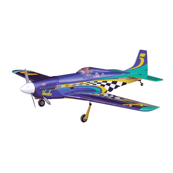
- Page 1 INSTRUCTION MANUAL 0.46-0.55Cubicinchdisplacement2-stroke 0.70 -0.81 Cubicinchdisplacement4-stroke equire : s 5- channel radiow/5standard servos and1lowprofileretractservo. Specifications Wing Span 57.5 in / 1460 mm Wing Area 580 sq in / 37.4 sq dm Flying Weight 6.8 lbs / 3100 g Fuselage Length 50.0 in / 1260 mm * Specifications are subject to change without notice.* Warning ! This model is not a toy.
-
Page 2: Before You Begin
VOODOO MUSTANG-46 I N D E X BEFORE YOU BEGIN P. 1 PARTS LIST P. 2 ASSEMBLY P. 3 -11 SAFETY PRECAUTIONS P.11 BEFORE YOU BEGIN Read through the manual before you begin, so you will have an overall idea of what to do. -
Page 3: Parts List
Parts List 1. MAIN WING -- 1 pair 14. COWLING -- 1 pc. TRANSPARENT 3D TEMPLATE -- 1 pc. 2. RETRACTABLE LANDING GEAR -- 1 pair SCREW PWA2.6x12mm -- 4 pcs SCREW KA3x16mm -- 8 pcs SILICON GROMMET d1.5xD6.5mm -- 4 pcs 3. - Page 4 Aileron Pre-glued Aileron Servo Lead Bottom View Landing Gear KA3x16mm KA3x16mm Screw 1.5mm Completed Bottom View Landing Gear 3x3mm Set Screw 3x3mm Set Screw 4.1mm Collar Completed Bottom View...
- Page 5 Please dry fit wing joiner into left and right wing to make sure they fit with the proper Main Wing dihedral angle, mark the wing joiner if necessary. Apply epoxy glue to both sides of all surfaces in contact. Use a stick to apply the glue to inner side of wing joiner sleeve, and apply the glue to wing joiner before putting them together.
-
Page 6: Aileron Servo
Ø 1mm pilot holes for World Models tri-horn are pre-drilled. Aileron Servo Please look for pin-hole marks at under side of control surfaces. Straper PB2x16mm Screw PB2x20mm Screw Fuel Tube TWM PL8210010 Ø6x5mm CLEVIS WRENCH PB2x16mm PB2x20mm Clevis Fuel Tube Ø6x5mm Tri-horn Pushrod... -
Page 7: Fuel Tank
Tail Landing Gear PA3x12mm Screw 2.1mm Collar PA3x12mm 1.5mm PM2x12mm Screw M2 Nut 3x3mm Set Screw 2.1mm Collar M2 Nut PM2x12mm Bottom View Engine Mount M4x25mm Socket Head Screw d4xD9mm Washer M4x25mm Socket Head Screw d4xD9mm Washer Apply thread locker to screws. Engine Mount PL511050 Fuel Tank... -
Page 8: Elevator Pushrod
Engine PM3.5x30mm Screw Installed Engine Position M3.5 Nut d3.5xD8mm d3.5xD8mm Washer 118 mm Washer 4.65 in. M3.5 Nut PM3.5x30mm Plastic Tube d2xD3x300mm Throttle Pushwire Ø1.2x430mm Please refer to the attached sheet for usage of the transparent 3D Cowling template. PWA2.6x12mm Screw d1.5xD6.5mm Silicon Grommet d1.5xD6.5mm... -
Page 9: Rudder Pushrod
Ø1mmpilotholesforWorldModelstri-hornarepre-drilled. Rudder Pushrod Pleaselookforpin-holemarksatundersideofcontrolsurfaces. PB2x12mm Screw TWM PL8210010 CLEVIS WRENCH Tri-horn M3x14mm(L) PB2x12mm Pushrod Ø1.8x657mm Clevis Fuel Tube Ø6x5mm Bottom View Servo Set 3x3mm Set Screw Linkage Connector 2mm Nut Washer Washer 2mm Washer 2m m Throttle Servo. Please refer to the attached sheet for linkage connector installation. Radio Equipment Install and arrange the servo as shown in the diagram. - Page 10 First insert the grommet to the canopy then apply screw. Canopy PWA2.3x8mm Screw d1.5xD6.5mm PILOT PC001063A Silicon Grommet d1.5xD6.5mm Silicon Grommet PWA2.3x8mm Double-sided Tape Main Wing PM4x30mm Screw d4xD15mm Washer PM4x30mm d4xD15mm Washer Bottom View PM3x13mm Air Scoop d3xD7mm Washer PM3x13mm Screw d3xD7mm Washer Bottom View...
- Page 11 Wing Setting Adjust the wing and fuselage configuration as shown in the diagrams. A = A ' B = B ' C = C ' P.10...
- Page 12 Adjust the control throws as shown in the diagram. Control Throws These throws are good for general flying. You can adjust according to your personal preference. Elevator 15mm 15mm Rudder 28mm 28mm Ailerons The ideal C.G. position is 128mm(5.04 in) behind the C.G.
- Page 13 LINKAGE CONNECTOR HW7111050 & HW7111060 Drill 2mm hole at servo horn. Insert linkage connector into servo horn. Make sure shoulder of screw is cleared from servo horn. Add washer to reduce play if necessary. Shoulder Tighten up the round nut against the shoulder.
- Page 14 Product Registration Form (US Customers) We would like to share with you any relevant information regarding your model, including product news and free upgrade parts when applicable. Please fill in the following and send to AirBorne Models, 4749-K,Bennett Drive, Livermore, CA 94551 USA. 1.
- Page 15 Usage of the transparent 3D template This transparent 3D template is used for position guidance of the actual cutting of the pre-painted cowling. Simply cut the transparent 3D template to fit your engine and exhaust pipe, then slide onto the actual cowling and use as template to mark the openings required for final cutting.
- Page 16 A090VDPO18840906...
Need help?
Do you have a question about the VOODOO MUSTANG-46 and is the answer not in the manual?
Questions and answers