Table of Contents
Advertisement
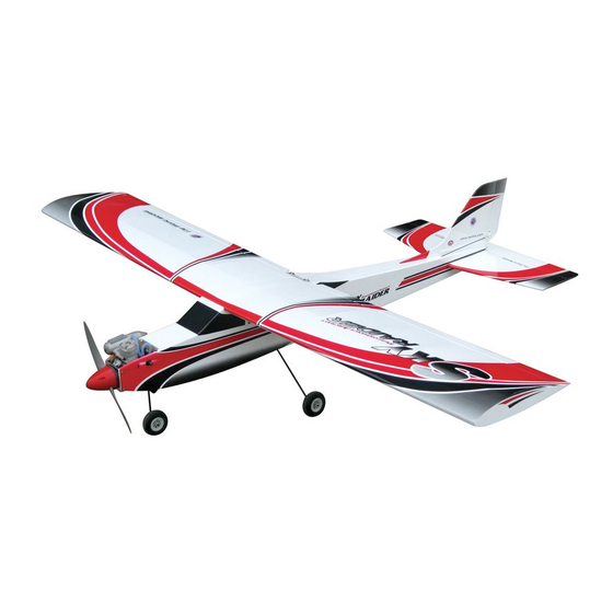
SKY
Mach I
0.40 0 46 Cubic inch displacement 2 stroke
- .
Requires: 4- channel
Wing Span
Wing Area
Flying Weight
Fuselage Length
Warning ! This model is not a toy.
It is designed for maximum performance. Please seek advice if one is not familiar with this kind
of engine powered precision model. Operating this model without prior preparation may cause
injuries. Remember, safety is the most important thing. Always keep this instruction manual
at hand for quick reference.
A177NPO24041005
RAIDER
radio
Specifications
* Specifications are subject to change without notice.*
td
INSTRUCTION MANUAL
w/ 4 standard servos
65.5 in / 1660 mm
725 sq in / 46.8 sq dm
5.5 lb / 2450 g
53.0 in / 1350 mm
ALMOST-READY-TO-FLY (ARF) SERIES
-
FACTORY PRE-FABRICATED
MADE IN CHINA
Advertisement
Table of Contents

Subscribe to Our Youtube Channel
Related Manuals for The World Models Manufacturing SKY RAIDER MACH-I


Summary of Contents for The World Models Manufacturing SKY RAIDER MACH-I
- Page 1 INSTRUCTION MANUAL RAIDER Mach I 0.40 0 46 Cubic inch displacement 2 stroke Requires: 4- channel radio w/ 4 standard servos Specifications Wing Span 65.5 in / 1660 mm Wing Area 725 sq in / 46.8 sq dm Flying Weight 5.5 lb / 2450 g Fuselage Length 53.0 in / 1350 mm...
-
Page 2: Before You Begin
RAIDER Mach I I N D E X BEFORE YOU BEGIN P. 1 PARTS LIST P. 2 ASSEMBLY P. 3 -11 SAFETY PRECAUTIONS P.11 BEFORE YOU BEGIN Read through the manual before you begin, so you will have an overall idea of what to do. Check all parts. -
Page 3: Parts List
Parts List 1. MAIN WING -- 1 pair 12. PUSHROD Ø1.8x840mm w/ Threads (For Elevator Servo) -- 1 pc. PLYWOOD (Tail Skid) 3mm -- 1 pc. 2. WING JOINER 8x27x200mm -- 1 pc. CLEVIS -- 1 pc. 3. PLYWOOD 3x10x20mm (For Aileron Servo Stand) -- 2 pcs FUEL TUBE Ø6x5mm -- 1 pc. - Page 4 Main Wing Pre-glued RIGHT WING Main Wing Please dry fit wing joiner into left and right wing to make sure they fit with the proper dihedral angle, mark the wing joiner if necessary. Apply epoxy glue to both sides of all surfaces in contact. Use a stick to apply the glue to inner side of wing joiner sleeve, and apply the glue to wing joiner before putting them together.
-
Page 5: Aileron Servo
Aileron Servo TWM PL8210010 CLEVIS WRENCH Pushrod Straper Ø1.8x130mm Fuel Tube Ø 6x5mm Fuel Tube Ø6 x 5mm Clevis Bottom View Ring Stabilizer & Elevator Pre-glued Completed Bottom View A177NPO24041005... - Page 6 Vertical Fin & Rudder Screw PM3 x 40mm Screw PM3 x 50mm Pre-glued Washer d3 x D7mm d3xD7mm Washer PM3x50mm PM3x40mm A=A' Completed Use thread locker when tightening screws. Don't use excessive force as you are dealing with balsa. A177NPO24041005...
-
Page 7: Fuel Tank
Fuel Tank Install Balsa 8 x 8 x 87 (For Fuel Tank Position Fixing) Fuel Tank 380cc Top View Engine Mount M3 x 20mm Socket Head Screw M3 x 20m Socket Head Screw Wa s h e r d 3 x D 7 m m d 3 x D 7 m m Engine Mount PL5111030 Apply thread locker to screws. -
Page 8: Main Landing Gear
Main Landing Gear Screw PA3 x 12mm 4.1mm Collar 4.1mm Collar C o l l a r 4 . 1 m m 3mm Set Screw Front Plate PA3 x 12mm Completed Bottom View PM2x10mm Screw M3x25mm Socket Head Screw M3x25mm Socket Head Screw d3xD7mm Washer 3.2mm... -
Page 9: Elevator Pushrod
Elevator Pushrod Tail Skid Screw PB2x12mm TWM PL8210010 CLEVIS WRENCH PB2x12mm Clevis Fuel Tube 6x5mm Ø Pushrod Horn Ø1.8x Ø1mm pilot holes for World Models tri-horn are pre-drilled. Please look for pin-hole marks at under side of control surfaces. Rudder Pushrod TWM PL8210010 CLEVIS WRENCH Screw... - Page 10 Servo Set 3x3mm Set Screw 3 X 3mm Set Screw Linkage Connector 2mm Nut Washer 2mm Washer Washer 2m m Throttle Servo. Please refer to the attached sheet for linkage connector installation. Install and arrange the servos as shown in the diagram. Servos Rudder Pushrod Ø1.8 x 850mm...
- Page 11 Wing Setting Adjust the wing and fuselage configuration as shown in the diagrams. A = A' B = B' C = C' P.10 A177NPO24041005...
-
Page 12: Important Safety Precautions
Control Throws Adjust the control throws as shown in the diagram. These throws are good for general flying. You can adjust according to your personal preference. Elevator 15mm 15mm Rudder 20mm 20mm Aileron C.G. The ideal C.G. position is 80mm (3.15 in) behind the leading edge measured at where the wing meets the fuselage. - Page 13 LINKAGE CONNECTOR HW7111050 & HW7111060 Drill 2mm hole at servo horn. Insert linkage connector into servo horn. Make sure shoulder of screw is cleared from servo horn. Add washer to reduce play if necessary. Shoulder Tighten up the round nut against the shoulder.
- Page 14 Product Registration Form (US Customers) We would like to share with you any relevant information regarding your model, including product news and free upgrade parts when applicable. Please fill in the following and send to AirBorne Models, 4749-K, Bennett Drive, Livermore, CA 94551 USA. 1.
- Page 15 180mm Extension Package Code No. Package Code No. Size Size Package Code No. Size Code No. Package Size Large Clevis Small Clevis Special tool for clevis installation. Suitable for standard and small Code No. Package ( EP) clevis. Size KP0041300 Code No SV4031 Package Code No.
- Page 16 The World Models Manufacturing Co., Ltd. www .thew orldm odels .com A177NPO24041005...
Need help?
Do you have a question about the SKY RAIDER MACH-I and is the answer not in the manual?
Questions and answers