Table of Contents
Advertisement
Quick Links
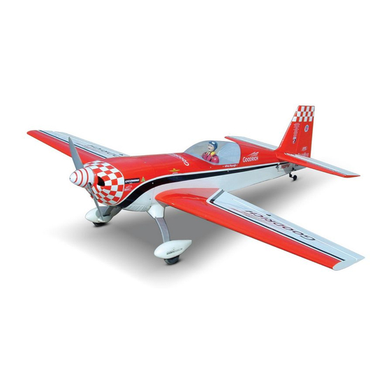
Extra 300S- 160R
1.60 cu.in. displacement 2 stroke (glow)
Requires : 4 - channel radio w/ 6 high torque servos
Wing Span
Wing Area
Flying Weight
Fuselage Length
Warning !This model is not a toy.
It is designed for maximum performance. Please seek advice if one is not familiar with this kind
of engine powered precision model. Operating this model without prior preparation may cause
injuries. Remember, safety is the most important thing. Always keep this instruction manual at
hand for quick reference.
The World Models
Manufacturing Co., Ltd.
www .thew orldm odels .com
A120NPO24791102
Specifications
* Specifications are subject to change without notice.*
INSTRUCTION MANUAL
-
80.5 in /2040mm
1175sq in / 75.5sq dm
14.0 lb / 6380g
71.0 in / 1800mm
ALMOST-READY-TO-FLY (ARF) SERIES
FACTORY PRE-FABRICATED
MADE IN CHINA
Advertisement
Table of Contents

Related Manuals for The World Models Manufacturing Extra 300S-160R


Summary of Contents for The World Models Manufacturing Extra 300S-160R
- Page 1 INSTRUCTION MANUAL Extra 300S- 160R 1.60 cu.in. displacement 2 stroke (glow) Requires : 4 - channel radio w/ 6 high torque servos Specifications 80.5 in /2040mm Wing Span Wing Area 1175sq in / 75.5sq dm Flying Weight 14.0 lb / 6380g Fuselage Length 71.0 in / 1800mm * Specifications are subject to change without notice.*...
-
Page 2: Before You Begin
Extra 300S- 160R I N D E X BEFORE YOU BEGIN P. 1 PARTS LIST P. 2 ASSEMBLY P. 3 -14 SAFETY PRECAUTIONS P.14 BEFORE YOU BEGIN Read through the manual before you begin, so you will have an overall idea of what to do. Check all parts. -
Page 3: Parts List
Parts List 15. TRI-HORN M3x14mm(L) (w/o-Base For Rudder) -- 2 sets 1. MAIN WING -- 1 pair METAL HINGES -- 10 pcs SCREW PM2x30mm -- 3 pcs M2 NUT -- 3 pcs 3. PUSHROD Ø1.8x135mm w/Threads (For Aileron) -- 2 pcs CLEVIS PL4112103 -- 2 pcs CLEVIS PL4112103 -- 2 pcs RIGGING COUPLER Ø1.8x27mm w/Threads (For Rudder) -- 2 pcs... - Page 4 Main Wing R e p l a c e C A h i n g e s b y m e t a l h i n g e s . G l u e t h e m e t a l h i n g e s t o w i n g a n d a i l e r o n b y e p o x y.
- Page 5 Engline Box Use epoxy glue to glue all parts together. Center line of firewall 7.5mm 7.5mm 7.5mm 7.5mm 13mm 13mm 7.5mm 7.5mm 7.5mm 7.5mm Blind nuts are off-centered to keep the spinner at the at the fuselage axis P . 4 A120NPO24791102...
-
Page 6: Engine Mount
Engine Box F21 A 99mm F21 B Use epoxy to glue all parts to gether Engine Mount M6x30mmSocket Head Screw d6xd15mm Washer Engine Mount Pl5911120 d6xD15mm M6x30mm Washer Socket Head Screw Apply thread locker to screws. P . 5 A120NPO24791102... -
Page 7: Fuel Tank
Fuel Tank CABLE TIE 1.5x8x500mm DOUBLE-SIDED TAPE 40x160mm Fuel Tank 800cc Km3x20mm Engine M4X35mm Screw 3.2mm 4mm Washer Make sure the rounded edges are facing the shock absorbing SILICON PAD M3 Nylon Insert Lock Nut M3 Nylon Insert Lock Nut KM3x20mm Screw 4.1mm 5.1mm... -
Page 8: Elevator Servo
Elevator Servo PWA 2x13mm PA3x12mm Stabilizer d3xD7mm 1.5mm Washer PA3x12 Screw PA3x12mm Stabilizer Tube Ø9.6x288mm d3xD7mm Washer Pre-glued 1.5mm Replace CA hinges by metal hinges.Glue the metal hinges to stabilizer and elevator by epoxy. Vertical Fin / Rudder Pre-glued Replace CA hinges by metal hinges. Glue the metal hinges to vertical fin and rudder by epxy. -
Page 9: Tail Landing Gear
Tail Landing Gear PA3x12mm Screw 2.6mm Collar 1.5mm 3mm set screw Sponge 2.6mm Collar PA3x12mm Throttle Servo Throttle pushwire F54A LINKAGE CONNECTOR Set Screw 3x3mm Linkage Connector M2 Nut Washer Throttle Servo Rudder Servo 1m m You may put throttle servo on the left or right Plywood 3x47x67mm PWA 2x12mm side to fit you engine position. -
Page 10: Rudder Pushrod
Rudder Pushrod PM2x30mm Screw 2mm Nut 2mm Nut Metal Rod Ø1.8x27mm w/Threads 2m m PM2x30mm Fuel Tube Ø6x5mm Copper Tube Ø1mm pilot holes for World Models tri-horn are pre-drilled.Please look for Pin-hole marks at under side of control surface. Bottom View Elevator Pushrod PB2x30mm Screw PB2x30mm... -
Page 11: Landing Gear
Landing Gear PWA2.3x8mm Screw M8 Nylon insert lock nut 4.1mm Plastis Wheel Collar 4.1mm Collar 3mm Set Screw PM3x12mm Screw 4x66mm Axle Shaft 3mm SetScrew Nylon insert lock nut Axle Shaft 90mm Main Wheel Plate 1mm 4.1mm Collar Wheel Pant PM3x12mm PWA2.3x8mm Bottom View... - Page 12 Main Wing Wing Tube 25x878mm Ø Wire Ø0.8mm Right Self Tightening Wing Latch Set Screw M3X6mm Wing Tube Completed Wing Tube Self Tightening Self Tightening Wing Tube Wing Latch Wing Latch right left P . 1 1 A120NPO24791102...
- Page 13 Cockpit HM3x22mm Screw d3xD7mm Washer HM3x22mm d3xD7mm Washer Cowling Make sure the screws hit the reinforcement plywood. Cowling PWA3x12mm Screw Silicon Grommet d1.5 x D6.5 mm Silicon Grommet d1.5xd6.5mm Fuselage PWA3 x 12 mm 1.5mm 1.5mm Spinner 3.5mm 3.5mm Ø89mm 3.5mm 3.5mm d1.5xd6.5mm Silicon Grommet...
-
Page 14: Control Throws
Canopy PWA 2.3x8mm Screw Silicon Grommet d1.5Xd6.5mm 3.5mm 3.5mm PWA 2.3x8mm d1.5xd6.5mm Silicon Grommet Apply double-sided tape Make sure the screws hit the reinforcement plywood. 1m m Wing Setting A = A' B = B' C= C' Control Throws Adjust the control throw as shown as shown in the diagram. - Page 15 #Pre-flight adjustment must be done before flying, it is very dangerous to fly a badly pre-adjusted aircraft. #Extra 300S-160R is specially designed to be powered by 1.60 2 stroke glow engine, using a more powerful engine does not mean better performance. In fact, over po wered engine may cause severe damage and injuries.
- Page 16 LINKAGE CONNECTOR HW7111050 & HW7111060 Drill 2mm hole at servo horn. Insert linkage connector into servo horn. Make sure shoulder of screw is cleared from servo horn. Add washer to reduce play if necessary. Shoulder Tighten up the round nut against the shoulder.
- Page 17 Product Registration Form (US Customers) We would like to share with you any relevant information regarding your model, including product news and free upgrade parts when applicable. Please fill in the following and send to AirBorne Models, 4749-K, Bennett Drive, Livermore, CA 94551 USA. 1.
-
Page 18: Optional Parts
Optional Parts ACCESSORIES 180mm Extension Clevis Wrench Package Package Code No. Size Code No. Size PL8210010 1 set KW0011800 180mm 1 set Large Clevis Small Clevis Special tool for clevis installation. Suitable for standard and small (EP)clevis. 180mm Y Cord Package Code No. - Page 19 A120NPO24791102...
Need help?
Do you have a question about the Extra 300S-160R and is the answer not in the manual?
Questions and answers