Table of Contents
Advertisement
Quick Links
Download this manual
See also:
User Manual
Advertisement
Table of Contents

Related Manuals for LSS ST17


Summary of Contents for LSS ST17
- Page 1 PROFESSIONAL AUDIO SYSTEM ST17 OPERATING MANUAL Ver. ST17-EN-1.1 LSS Advanced Speaker Systems Via On. Longo 53-89024 Polistena (RC) ITALY Tel (39) 966 9321299 – Fax (39) 966 933007 Email: info@lss.it - Internet: www.lss.it...
- Page 2 Every precaution has been taken in the preparation of this manual. Nevertheless, LSS assumes no responsibility for errors or omissions. Neither is any liability assumed for damages resulting from the use of the information contained in this publication.
-
Page 3: Table Of Contents
BUMPER AND SYSTEM HANGING ..................... 17 ARRAY SIMULATOR SOFTWARE ....................... 18 INSTALLATION ON A POLE ........................19 TRANSPORT OF SPEAKERS ....................... 19 ELECTRICAL CONNECTION......................... 20 WEEE DIRECTIVE ............................22 DIMENSIONS ..............................23 NOTES ................................24 Operating Manual ver. ST17-EN-1.1 |3... -
Page 4: Introduction
LSS produces professional audio products – the result of exceptional engineering and meticulous craftsmanship. This manual is intended for use with LSS loudspeaker. This includes: safety precautions; installation, set-up and operating instruction. Please read this manual plus any accompanying manual and follow all relevant precautions and instructions. -
Page 5: Safety And Warning
LSS loudspeakers can produce sound levels capable of causing permanent hearing damage from prolonged exposure. The higher the sound level, the less exposure needed to cause such damage CAUTION: This product is energized as long as it is connected to the AC. -
Page 6: Controls And Inspections
The flow rates of suspension accessories provided by LSS are certified by a qualified consultant external to the Company. The original document is available at the LSS office. -
Page 7: Application
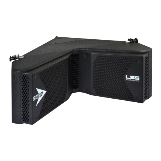
______________________________________________________________________________ APPLICATION ST17 is a high definition line array system designed specifically for vertical curvilinear array that provides high output, distortion sound reinforcement for the entire range of pro audio application. The 152 (6") mm low frequency cone with 45 mm (1.75") voice coil with Neodymium magnet and 75 mm (3") voice coil high frequency compression... -
Page 8: Technical Specifications
Texture poliurethanic black Finish paint Powder coated perforated Grille MECHANYCAL steel with anti dust foam Connectors 2 Neutrik NL4 Speakon Coupling and suspension hardware (included), Flight Accessories Case for 4 ST17, Pole mount adapter (optional), 8| Operating Manual ver. ST17-EN-1.1... -
Page 9: Installation And Wiring
ST17is a line array system designed for vertical curvilinear array that can be used both in flying or stacking configuration. Maximum number of Maximum number of speakers in Stacking speakers in Flying configuration is 4 configuration is 16 Operating Manual ver. ST17-EN-1.1 |9... - Page 10 ST17__________________________________________________________________________________ It is recommended to use ST17 together with the sub SB17. They have the same mounting hardware and similar shape in order to facilitate the creation of arrays. Maximum number of Maximum number of speakers in Stacking speakers in Flying...
-
Page 11: Mounting The Array
Bottom Rigging Holes Bottom Rigging Holes The bracket with rigging holes has a female side and a male side in order to facilitate the snap-in mounting of more speakers. Female side of bracket Male side of bracket Operating Manual ver. ST17-EN-1.1 |11... - Page 12 ST17__________________________________________________________________________________ Overlap the speakers aligning the rigging holes, then secure them with the quick release pins. The bracket for the regulation of inclination is in the rear of the case. 12| Operating Manual ver. ST17-EN-1.1...
- Page 13 ______________________________________________________________________________ Rear brackets of two overlapping speakers must be connected via the connecting bracket. Align the holes in the desired position, then secure them with the quick release pins. Operating Manual ver. ST17-EN-1.1 |13...
- Page 14 Value of the degrees of inclination for each hole are shown on the printed label on the plate: 0°-1.25°-2.5°-3.75°-5°-6.25°-7.5°-8.75°-10°. SB17 LABEL Sub's Plates Regulation Holes Connecting ST17 LABEL Top Speaker’s Bracket Plates ST17 400W 16 Ohm Bottom Speaker’s Plates 14| Operating Manual ver. ST17-EN-1.1...
-
Page 15: Installation On Bumper
The fixing method of the first case to the bumper takes place in the same way of fastening between multiple speakers: attach the speaker to the sides via rigging holes, then connect the rear bracket adjusting the inclination. Operating Manual ver. ST17-EN-1.1 |15... - Page 16 ST17__________________________________________________________________________________ In case of installation in Flying mode, use the bumper without feet, attach the speaker to the sides via rigging holes, then connect the rear bracket adjusting the inclination. 16| Operating Manual ver. ST17-EN-1.1...
-
Page 17: Bumper And System Hanging
To pull back the system, connect an eyebolt to the rear speaker plates and a rope or a chain, then manage the inclination. Operating Manual ver. ST17-EN-1.1 |17... -
Page 18: Array Simulator Software
- Preset for the areas of listening and the setup of the array. - Display Pressure Levels (SPL). ……………………. *To receive the software or to have more information, contact your LSS distributors or send an email to tech@lss.it. 18| Operating Manual ver. ST17-EN-1.1... -
Page 19: Installation On A Pole
Install the bumper on the pole mount adapter, then secure them with the quick release pins. TRANSPORT OF SPEAKERS If you need to move the speakers it is possible to use a flight case on wheels. It may contain up to four ST17. Operating Manual ver. ST17-EN-1.1 |19... -
Page 20: Electrical Connection
IN is the input connector and must be connected to the amplifier, ‘OUT’ can be used to connected other systems. Speakers of ST17 are linked on pins 1+ 1-. Channel 2 has been linked from In to the out. ST17... - Page 21 LSS. One output channel drive the SB17 and another one drive the ST17. If your amplifier can manage a 2 Ohms Load and has sufficient power, itis possible to connect a maximum of 6ST17 in parallel per channel or 4 SB17 in parallel per channel (total impedance will be 2 Ohms).
-
Page 22: Weee Directive
Warning: If the product is used for business purposes, the following steps to delete it: contact your LSS dealer for information about the product recall. Might be charged for the costs of collection and recycling. Small products (and amounts) might be taken back by your local collection facilities. -
Page 23: Dimensions
______________________________________________________________________________ DIMENSIONS SIDE FRONT REAR 52cm 58cm 58cm BOTTOM Operating Manual ver. ST17-EN-1.1 |23... -
Page 24: Notes
ST17__________________________________________________________________________________ NOTES 24| Operating Manual ver. ST17-EN-1.1... - Page 25 ______________________________________________________________________________ CONTACT INFORMATION: LSS Advanced Speaker Systems Via On. Longo 53 89024 Polistena (RC) ITALY Tel (39) 966 9321299 – Fax (39) 966 933007 Email: info@lss.it - Internet: www.lss.it Operating Manual ver. ST17-EN-1.1 |25...
Need help?
Do you have a question about the ST17 and is the answer not in the manual?
Questions and answers