Nordson Vantage Customer Product Manual
Manual spray gun control unit
Hide thumbs
Also See for Vantage:
- Customer product manual (62 pages) ,
- Customer product manual (52 pages) ,
- Customer product manual (30 pages)
Table of Contents
Advertisement
Quick Links
Download this manual
See also:
Customer Product Manual
r
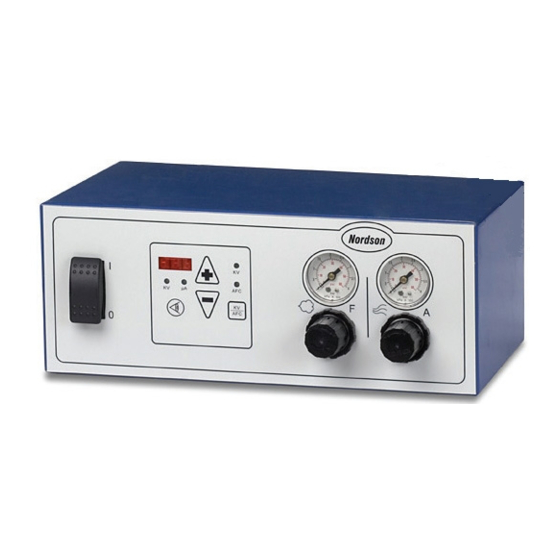
Vantage
Manual Spray Gun Control Unit
Customer Product Manual
Part 1066850-03
Issued 04/16
For parts and technical support, call the Industrial Coating
Systems Customer Support Center at (800) 433-9319 or
contact your local Nordson representative.
This document is subject to change without notice.
Check http://emanuals.nordson.com for the latest version.
NORDSON CORPORATION • AMHERST, OHIO • USA
Advertisement
Table of Contents

Subscribe to Our Youtube Channel
Related Manuals for Nordson Vantage


Summary of Contents for Nordson Vantage
- Page 1 For parts and technical support, call the Industrial Coating Systems Customer Support Center at (800) 433-9319 or contact your local Nordson representative. This document is subject to change without notice. Check http://emanuals.nordson.com for the latest version. NORDSON CORPORATION • AMHERST, OHIO • USA...
-
Page 2: Table Of Contents
......Contact Us Notice This is a Nordson Corporation publication which is protected by copyright. Nordson Corporation welcomes requests for information, comments, and Original copyright date 2006. No part of this document may be inquiries about its products. - Page 3 Change Record Change Record Revision Date Change 04/16 Removed approval labels and DOC. Part 1066850-03 E 2016 Nordson Corporation...
- Page 4 Change Record Part 1066850-03 E 2016 Nordson Corporation...
-
Page 5: Safety
Make sure all equipment is rated and approved for the environment in which it is used. Any approvals Read and follow these safety instructions. Task- obtained for Nordson equipment will be voided if and equipment-specific warnings, cautions, and instructions for installation, operation, and service instructions are included in equipment are not followed. -
Page 6: Fire Safety
Use only replacement parts that are designed grounding strap connected to the gun handle or for use with original equipment. Contact your other true earth ground. Nordson representative for parts information Shut off electrostatic power supplies and and advice. ground gun electrodes before making adjustments or cleaning powder spray guns. -
Page 7: Description
Fluidizing 0.1−0.3 bar (2−5 psi) Operating Modes Electrical Requirements Input Requirements 85−250 Vac, 1 phase, The Vantage Manual Spray Gun Control Unit has 50−60 Hz, 40 VA two operating modes: Voltage Output 0−21 Vdc, 0.60 A (To Spray Gun) kV: Operator may adjust the voltage output Installation Requirements (per ANSI/ISA S82.01) -
Page 8: Front Panel
/ AFC Mode Key Changes the operating mode between kV and AFC View Key Switches the unit of measure (kV or μA) being displayed on the digital display u u A A Figure 1 Front Panel Part 1066850-03 E 2016 Nordson Corporation... -
Page 9: Back Panel
MOTOR CTL. INPUT Separate only in a Non−Hazardous area Figure 2 Back Panel Note: The vibratory motor control (5) and gun air (7) connections are optional. If they are not used, they will be plugged. Part 1066850-03 E 2016 Nordson Corporation... -
Page 10: Installation
WARNING: When installing motor to the Vantage Controller to use the vibrator box feed option, the cord on the motor must be extra hard usage. The strain relief provided is rated for 4.3−11.4 mm dia. - Page 11 Vantager Manual Spray Gun Control Unit CONTROL UNIT TYPE DEFAULT (VANTAGE Control Unit) OPTIONAL (Econo-Coat Control Unit Retrofit) DEFAULT OPTIONAL (IPS SPRAY GUNS) (TRIBOMATIC SPRAY GUN) GUN TYPE Figure 3 Circuit Board Configuration Part 1066850-03 E 2016 Nordson Corporation...
-
Page 12: Mounting Brackets
5. Place the controller and bracket on the booth’s operator platform railing (3). 6. Tighten the machine screws until the bracket is secured to the rail. Tighten the jam nuts against the bracket to lock the machine screws in place. Part 1066850-03 E 2016 Nordson Corporation... -
Page 13: Wall-Mounting Bracket
1. Control unit 6. Hex nuts 2. Wall-mounting bracket 7. Lock washers 3. M5 Pan-head screws 8. Flat washers 4. Lock washers 9. M8 Pan-head screws 5. Flat washers Part 1066850-03 E 2016 Nordson Corporation... -
Page 14: Connections
(Blue) 0−7 BAR NOTE: Tighten the gun cable retaining nut to 6 NSm (4.4 ft-lb). An optional 4-meter extension cable is available. Do not add more than two extension cables to the gun cable. Part 1066850-03 E 2016 Nordson Corporation... -
Page 15: Power Input Cord
Note: Typical powder pump and hopper shown. Connections for a vibratory box feeder system are slightly different than those shown. Power Input Cord Connect the power input cord to a plug or electrical panel using these guidelines: Wire Color Function Blue N (neutral) Brown L (hot) Green/Yellow GND (ground) Part 1066850-03 E 2016 Nordson Corporation... -
Page 16: Operation
2. Set the supply air pressure to 5−7 bar NOTE: The following air pressure settings are (80−100 psi). average starting points. Experimentation will be 3. Install the appropriate coating material source. necessary to achieve the desired results. Part 1066850-03 E 2016 Nordson Corporation... -
Page 17: Shutdown
Check power and gun cable connections. Make sure that the air being supplied to the control unit is clean and dry. Wipe off the control unit with a clean, dry cloth. Part 1066850-03 E 2016 Nordson Corporation... -
Page 18: Troubleshooting
If you cannot WARNING: Allow only qualified personnel solve the problem with the information given here, to perform the following tasks. Follow the contact your local Nordson representative for help. safety instructions in this document and all other related documentation. Problem... -
Page 19: Nordson Corporation
With the trigger switch actuated, check for 21 Vdc between pins 2 and 3 of the gun end of the gun cable. If the reading is not 21 Vdc, contact your Nordson representative. No kV output and no Malfunctioning solenoid valve Replace the solenoid valve. -
Page 20: Electrical Schematic
Vantager Manual Spray Gun Control Unit Electrical Schematics See Figure 8. Figure 8 Electrical Schematic for Vantage Controller without Vibratory Motor Control Part 1066850-03 E 2016 Nordson Corporation... - Page 21 Vantager Manual Spray Gun Control Unit Figure 9 Electrical Schematic for 220Vac Vantage Controller with Vibratory Motor Control Part 1066850-03 E 2016 Nordson Corporation...
- Page 22 Vantager Manual Spray Gun Control Unit Figure 10 Electrical Schematic for 115Vac Vantage Controller with Vibratory Motor Control Part 1066850-03 E 2016 Nordson Corporation...
-
Page 23: Pneumatic Schematic
Figure 11 Pneumatic Schematic Note: If a Sure Coat gun is used with this control unit, order a 4-mm air fitting, part 288822, to install in place of the manifold’s gun air pipe plug, part 1043873. Part 1066850-03 E 2016 Nordson Corporation... -
Page 24: Repair
Failure to observe this Pneumatic Schematic on page 19 for air tubing warning may result in personal injury. connections. Figure 12 Regulator Assembly Replacement 1. Air tubing 3. Regulator seal 4. Mounting nut 2. Regulator assembly Part 1066850-03 E 2016 Nordson Corporation... -
Page 25: Circuit Board Replacement
10. Perform the Gun Type Configuration procedure on page 12 to select which type of gun will be 9. Install the new solenoid valve assembly by connected to the control unit. performing this procedure in reverse. Part 1066850-03 E 2016 Nordson Corporation... -
Page 26: Nordson Corporation
1. Solenoid wiring harness 3. Hex nuts and washers 5. Circuit board 2. Triple elbow 4. Solenoid valve Note: The pipe plug and 8-mm elbow are on the underside of the solenoid valve (4). Part 1066850-03 E 2016 Nordson Corporation... -
Page 27: Parts
The number in the Part column is the Nordson Letters in the Note column refer to notes at the end Corporation part number. A series of dashes in this of each parts list. -
Page 28: External Control Unit Parts
E: If you use this control unit with a Sure Coat manual powder spray gun, order a 4-mm fitting, part 288822, to use in place of this pipe plug. Contact your Nordson representative for more information about using a Sure Coat gun with the Vantage control unit. - Page 29 Vibratory Motor Control Detail A u u A A Figure 14 External Control Unit Parts Note: The ground assembly shown in Detail A is also on the inside of the control unit cabinet cover. Part 1066850-03 E 2016 Nordson Corporation...
-
Page 30: Internal Control Unit Parts
G: Use only with control units with vibratory motor control. H: Use only with the 115Vac Vantage control unit with vibratory motor control. I: Use this kit with the 115V and 220V control units with vibratory motor control. If you are not going to use the vibratory motor control option, the plug kit will help maintain a dust tight control box. - Page 31 Vantager Manual Spray Gun Control Unit Detail B Detail C Figure 15 Internal Control Unit Parts Part 1066850-03 E 2016 Nordson Corporation...
-
Page 32: Optional Mounting Brackets
NOTE A: One pair of these screws will not be used. Two pairs are included to accommodate different rail sizes. B: These screws replace three of the screws in the control unit’s access cover. Figure 16 Rail-Mounting Bracket Part 1066850-03 E 2016 Nordson Corporation... -
Page 33: Wall-Mounting Bracket
S WASHER, flat, regular, 8, steel, zinc 982563 S SCREW, pan head, slotted, M8 x 40 NOTE A: Use these screws in place of the M5 x 10 screws that are installed in the control unit. Figure 17 Wall-Mounting Bracket Part 1066850-03 E 2016 Nordson Corporation... -
Page 34: Air Tubing, Powder Tubing, And Fittings
C: If a Sure Coat gun is used with this control unit, order this 4-mm connector to install in place of the manifold’s gun air pipe plug, part 1043873. Contact your Nordson representative for more information about using a Sure Coat gun with the Vantage control unit.
Need help?
Do you have a question about the Vantage and is the answer not in the manual?
Questions and answers