Nordson ValveMate 7197PCP-2K Operating Manual
Hide thumbs
Also See for ValveMate 7197PCP-2K:
- Quick start manual (10 pages) ,
- Quick start manual (10 pages)

Subscribe to Our Youtube Channel
Related Manuals for Nordson ValveMate 7197PCP-2K


Summary of Contents for Nordson ValveMate 7197PCP-2K
- Page 1 ValveMate 7197PCP-2K Controller Operating Manual ™ Electronic pdf files of Nordson EFD manuals are also available at www.nordsonefd.com...
- Page 2 Thank You! You have just purchased the world’s finest precision dispensing equipment. I want you to know that all of us at Nordson EFD value your business and will do everything in our power to make you a satisfied customer.
-
Page 3: Table Of Contents
Changing the IP Address of the Controller ........................37 Operation ..................................38 Routine Startup ................................38 Errors and Emergency Stops (ESTOP) ........................38 Disabling a Pump ...............................39 Longterm Shutdown ..............................39 Continued on next page www.nordsonefd.com info@nordsonefd.com +1-401-431-7000 Sales and service of Nordson EFD dispensing systems are available worldwide. - Page 4 Maximum Motor Speed Based on Viscosity ......................47 Motor Port Pin Assignments ............................48 Appendix A, Changing the IP Address of a Computer ....................49 Appendix B, Example Volume Program ........................51 www.nordsonefd.com info@nordsonefd.com +1-401-431-7000 Sales and service of Nordson EFD dispensing systems are available worldwide.
-
Page 5: Introduction
As with all EFD products, the ValveMate 7197PCP-2K Controller has been produced to exacting specifications and thoroughly tested prior to shipment. To obtain maximum performance from this equipment, read this manual carefully. www.nordsonefd.com info@nordsonefd.com +1-401-431-7000 Sales and service of Nordson EFD dispensing systems are available worldwide. -
Page 6: Nordson Efd Product Safety Statement
Hot surfaces! Avoid contact with the hot metal surfaces of heated components. If contact can not be avoided, wear heat-protective gloves and clothing when working around heated equipment. Failure to avoid contact with hot metal surfaces can result in personal injury. www.nordsonefd.com info@nordsonefd.com +1-401-431-7000 Sales and service of Nordson EFD dispensing systems are available worldwide. -
Page 7: Halogenated Hydrocarbon Solvent Hazards
Qualified personnel are those employees or contractors who are trained to safely perform their assigned tasks. They are familiar with all relevant safety rules and regulations and are physically capable of performing their assigned tasks. www.nordsonefd.com info@nordsonefd.com +1-401-431-7000 Sales and service of Nordson EFD dispensing systems are available worldwide. -
Page 8: Intended Use
Make sure all equipment is rated and approved for the environment in which it is used. Any approvals obtained for Nordson EFD equipment will be voided if instructions for installation, operation, and service are not followed. If the equipment is used in a manner not specified by Nordson EFD, the protection provided by the equipment may be impaired. -
Page 9: Fire Safety
• Test: Verify the operation of features and the performance of equipment using the appropriate sections of this manual. Return faulty or defective units to Nordson EFD for replacement. • Use only replacement parts that are designed for use with the original equipment. Contact your Nordson EFD representative for information and advice. -
Page 10: Important Disposable Component Safety Information
Disconnect and lock out system electrical power. If using hydraulic and pneumatic shutoff valves, close and relieve pressure. For Nordson EFD air-powered dispensers, remove the syringe barrel from the adapter assembly. For Nordson EFD electro-mechanical dispensers, slowly unscrew the barrel retainer and remove the barrel from the actuator. -
Page 11: Specifications
WEEE Directive This equipment is regulated by the European Union under WEEE Directive (2012/19/EU). Refer to www.nordsonefd.com/WEEE for information about how to properly dispose of this equipment. www.nordsonefd.com info@nordsonefd.com +1-401-431-7000 Sales and service of Nordson EFD dispensing systems are available worldwide. -
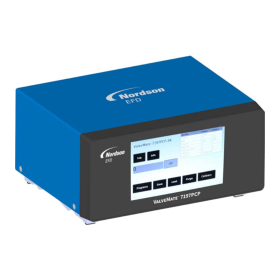
Page 12: Operating Features
Operating Features Touchscreen Foot pedal Pump motor port cable ports Power switch Power supply Ethernet port port Equipment I/O port (shown ground with ESTOP jumper installed) www.nordsonefd.com info@nordsonefd.com +1-401-431-7000 Sales and service of Nordson EFD dispensing systems are available worldwide. -
Page 13: Installation
Power cord and power supply, 24V, 90 W Foot pedal (P/N 7014865) ESTOP jumper, DB-15 (Not shown) 797PCP-2K pumps (ordered separately) 797PCP-2K pump motor cables (ordered separately) Quick start guide www.nordsonefd.com info@nordsonefd.com +1-401-431-7000 Sales and service of Nordson EFD dispensing systems are available worldwide. -
Page 14: Install The 797Pcp-2K Pumps
I/O port. Refer to “I/O Port Pin Assignments and Wiring Diagrams” on page 44 for wiring details. Contact your Nordson EFD representative for assistance in obtaining a breakout board and cable. www.nordsonefd.com info@nordsonefd.com +1-401-431-7000 Sales and service of Nordson EFD dispensing systems are available worldwide. -
Page 15: Connect Power
Connect the Pump Motor Cables Connect the 797PCP-2K pump motor cables to the MOTOR 1 and MOTOR 2 ports on the controller. 797PCP-2K www.nordsonefd.com info@nordsonefd.com +1-401-431-7000 Sales and service of Nordson EFD dispensing systems are available worldwide. -
Page 16: Connect A Purge Initiate Signal (Optional)
NOTE: A ValveMate 7197PCP-2K Controller’s preprogrammed IP address is 192.168.10.51. If there are multiple ValveMate 7197PCP-2K Controllers on the same network, they each need a unique IP address: • To change the IP address of a ValveMate 7197PCP-2K Controller, refer to “Changing the IP Address of the Controller” on page 37. -
Page 17: Initial Startup And Calibration
Select BACK (desktop) or REFRESH (web) to return to the Main screen. Continue to “Purge the Pumps” on page 18. ValveMate 7197PCP-2K Touchscreen 7197PCP-2K Web Calibrate screen, web interface Calibrate screen, touchscreen interface www.nordsonefd.com info@nordsonefd.com +1-401-431-7000 Sales and service of Nordson EFD dispensing systems are available worldwide. -
Page 18: Purge The Pumps
Before installing the mixer, determine and enter the correct settings for your Part A (Pump 1) and Part B (Pump 2) components. Nordson EFD recommends using the Volume program for this part of the installation process. Refer to “Appendix B, Example Volume Program” on page 51 to complete the installation process. -
Page 19: Installation Example
Bleed valve 1.0L tank 797PCP-2K 7197PCP-2K Static mixer ValveMate Controller Fluid inlet fitting Back view of controller, showing the pump motor cable connections www.nordsonefd.com info@nordsonefd.com +1-401-431-7000 Sales and service of Nordson EFD dispensing systems are available worldwide. -
Page 20: Programming
NOTE: Making an Ethernet connection allows you to also control the system via a web interface. Refer to “Make the Ethernet Connection (Optional)” on page 16 for details. This section applies to the ValveMate 7197PCP-2K touchscreen interface. The 7197PCP web interface functions in the same manner except for the following: (1) The Programs screen is eliminated and (2) the settings for both pumps are present on the Line, Volume, Weight, Teach, and Timed screens. -
Page 21: Entering Values On The Touchscreen
Line Program settings. ValveMate 7197PCP-2K Touchscreen 7197PCP-2K Web Variable table: The content of this table changes based on the selected program / variables. www.nordsonefd.com info@nordsonefd.com +1-401-431-7000 Sales and service of Nordson EFD dispensing systems are available worldwide. -
Page 22: Status Indications
The pump is not running. Running Green The system is running normally. ESTOP An emergency stop has occurred. Error Yellow An error has occurred. Refer to “Troubleshooting” on page 42. www.nordsonefd.com info@nordsonefd.com +1-401-431-7000 Sales and service of Nordson EFD dispensing systems are available worldwide. -
Page 23: Switching Pump Screens
Select this button to toggle between the Pump 1 and Pump 2 screens On the ValveMate 7197PCP-2K Controller touchscreen, the editable settings for Pump 1 and Pump 2 are on separate screens (Line program screen shown) On the 7197PCP-2K web interface, all editable settings for... -
Page 24: Flowchart Of Controller Screens (Valvemate 7197Pcp-2K)
(Pump 2 screen not shown) (Pump 2 screen not shown) Volume screen, Pump 1 Teach Program screen, Pump 1 (Pump 2 screen not shown) (Pump 2 screen not shown) www.nordsonefd.com info@nordsonefd.com +1-401-431-7000 Sales and service of Nordson EFD dispensing systems are available worldwide. -
Page 25: Flowchart Of Controller Screens (7197Pcp-2K Web Application)
Load screen Save screen Purge screen Log screen Calibrate screen Main screen Line Program screen Weight Program screen Timed Program screen Volume Program screen Teach Program screen www.nordsonefd.com info@nordsonefd.com +1-401-431-7000 Sales and service of Nordson EFD dispensing systems are available worldwide. -
Page 26: Adjusting The Purge Speed Setting
Sets the purge motor speed in RPM; for guidance on setting the RPM, refer to “Maximum Motor Speed Based on Viscosity” on page 47. Info Select to view information about the current screen, including the range limits for settings. www.nordsonefd.com info@nordsonefd.com +1-401-431-7000 Sales and service of Nordson EFD dispensing systems are available worldwide. -
Page 27: Creating Programs
On the touchscreen interface, program / variables. The all program type buttons are on settings for both pumps the Programs screen are shown side by side. www.nordsonefd.com info@nordsonefd.com +1-401-431-7000 Sales and service of Nordson EFD dispensing systems are available worldwide. - Page 28 Library (Save Screen)” on page 34. ValveMate 7197PCP-2K Touchscreen 7197PCP-2K Web Line program screen, web interface Line program screen, touchscreen interface Example of general programming steps (Line program screen shown) www.nordsonefd.com info@nordsonefd.com +1-401-431-7000 Sales and service of Nordson EFD dispensing systems are available worldwide.
-
Page 29: Line Programs
(pins 12 and 13 of the I/O port; refer to “I/O Port Pin Analog RPM: 0V 10–150 Assignments and Wiring Diagrams” on page 44 as needed) www.nordsonefd.com info@nordsonefd.com +1-401-431-7000 Sales and service of Nordson EFD dispensing systems are available worldwide. -
Page 30: Volume Programs
Because rotors and stators may not be perfectly matched, the Correction Factor (adjustable in Factor linearly scales the output to ensure that the expected amount is increments of 0.01) deposited every time. www.nordsonefd.com info@nordsonefd.com +1-401-431-7000 Sales and service of Nordson EFD dispensing systems are available worldwide. -
Page 31: Weight Programs
“Maximum Motor Speed Based on Viscosity” on page 47. Pump Size 0.01 mL, 0.05 mL, or Select the size of the pump for which you are creating the program. 0.15 mL www.nordsonefd.com info@nordsonefd.com +1-401-431-7000 Sales and service of Nordson EFD dispensing systems are available worldwide. -
Page 32: Teach Programs
Because rotors and stators may not be perfectly matched, the (adjustable in Correction Factor linearly scales the output to ensure that the increments of 0.01) expected amount is deposited every time. www.nordsonefd.com info@nordsonefd.com +1-401-431-7000 Sales and service of Nordson EFD dispensing systems are available worldwide. -
Page 33: Timed Programs
(adjustable in cycle. increments of 0.001 ms) NOTE: In other words, the Dispense Time is adjustable between 1 ms (0.001 s) and 10 minutes (600,000 ms). www.nordsonefd.com info@nordsonefd.com +1-401-431-7000 Sales and service of Nordson EFD dispensing systems are available worldwide. -
Page 34: Saving A Program To The Program Library (Save Screen)
Used to save a program to the Program Library. Change IP address: 192.168.10. Used to change the IP address of the controller. Refer to “Changing the IP Address of the Controller” on page 37. www.nordsonefd.com info@nordsonefd.com +1-401-431-7000 Sales and service of Nordson EFD dispensing systems are available worldwide. -
Page 35: Opening A Saved Program (Load Screen)
Select SUBMIT. The selected program loads into the variable table. Select BACK (touchscreen) or HOME (web) to return to the Main screen. ValveMate 7197PCP-2K Touchscreen 7197PCP-2K Web Load screen, web interface Load screen, touchscreen interface www.nordsonefd.com info@nordsonefd.com +1-401-431-7000 Sales and service of Nordson EFD dispensing systems are available worldwide. -
Page 36: Viewing The System Information
The system information is displayed on the Save screen. Select BACK (touchscreen) or HOME (web) to return to the Main screen. ValveMate 7197PCP-2K Touchscreen 7197PCP-2K Web Save screen, web interface Save screen, touchscreen interface www.nordsonefd.com info@nordsonefd.com +1-401-431-7000 Sales and service of Nordson EFD dispensing systems are available worldwide. -
Page 37: Changing The Ip Address Of The Controller
Changing the IP Address of the Controller A ValveMate 7197PCP-2K Controller must have a unique IP address. If a controller is connected to a network that includes another device with the same IP address, follow this procedure to change the IP address of a ValveMate 7197PCP-2K Controller. -
Page 38: Operation
Follow these recommended procedures for daily / routine startup and shutdown to obtain the best performance from your system. Power switch Routine Startup Switch on the power for all ValveMate 7197PCP-2K Controllers in the system. CAUTION Risk of equipment damage. Do not operate a 797PCP-2K without material. -
Page 39: Disabling A Pump
Longterm Shutdown For long periods of downtime or for storage, refer to the applicable pump manual to remove the pump stator(s). Removing the stator prevents rotor deformation. www.nordsonefd.com info@nordsonefd.com +1-401-431-7000 Sales and service of Nordson EFD dispensing systems are available worldwide. -
Page 40: Calibration
Select BACK to return to the Main screen. NOTE: When you select a program, the Calibrate radio button automatically deselects. ValveMate 7197PCP-2K Touchscreen 7197PCP-2K Web Calibrate screen, web interface Calibrate screen, touchscreen interface www.nordsonefd.com info@nordsonefd.com +1-401-431-7000 Sales and service of Nordson EFD dispensing systems are available worldwide. -
Page 41: Firmware Update
797PCP-2K pumps and the pump motor cables are ordered separately. Refer to the 797PCP-2K manual for part numbers. Accessories Part # Description 7364775 Breakout board and DB-15 cable (for Internet connectivity) Replacement Parts Part # Description 7014865 Foot pedal www.nordsonefd.com info@nordsonefd.com +1-401-431-7000 Sales and service of Nordson EFD dispensing systems are available worldwide. -
Page 42: Troubleshooting
Replace the cable if it is damaged. No counter feedback Faulty printed circuit board Cycle the controller power. If the problem persists, contact your Nordson EFD representative for Encoder feedback error assistance. www.nordsonefd.com info@nordsonefd.com +1-401-431-7000 Sales and service of Nordson EFD dispensing systems are available worldwide. -
Page 43: General Troubleshooting
Program not enabled Ensure that the program is enabled by selected the enable / disable radio button; program variables can be changed only after a program is enabled. www.nordsonefd.com info@nordsonefd.com +1-401-431-7000 Sales and service of Nordson EFD dispensing systems are available worldwide. -
Page 44: Technical Data
Error (output) Output Running (out) Input Purge (+) Input Purge (-) Input Analog in (0–10V) Analog GND Input External 24V input Output 24 VDC (100 mA) out www.nordsonefd.com info@nordsonefd.com +1-401-431-7000 Sales and service of Nordson EFD dispensing systems are available worldwide. -
Page 45: Sourcing Wiring Diagram For Connecting The Cycle Initiate (Ex_Trig)
Pin 6: Ex_Trig (-) Pin 5: Ex_Trig (+) Wiring Diagram for Connecting the Emergency Stop (ESTOP) Circuit Pin 2: Estop_L NC (normally closed) Pin 1: Estop_H www.nordsonefd.com info@nordsonefd.com +1-401-431-7000 Sales and service of Nordson EFD dispensing systems are available worldwide. -
Page 46: Wiring Diagrams For Connecting The Purge Initiate Circuit
Pin 10: Purge (+) Pin 9: GND Sinking Pin 15: 24 VDC Pin 11: Purge (-) External contact Pin 10: NO (normally open) Purge (+) Pin 9: GND www.nordsonefd.com info@nordsonefd.com +1-401-431-7000 Sales and service of Nordson EFD dispensing systems are available worldwide. -
Page 47: Maximum Motor Speed Based On Viscosity
25,000–50,000 mPa s 50,000–150,000 mPa s Viscosity 1000 5000 7500 10000 12500 15000 20000 30000 40000 50000 75000 100000 125000 150000 200000 250000 Viscosity in mPa s www.nordsonefd.com info@nordsonefd.com +1-401-431-7000 Sales and service of Nordson EFD dispensing systems are available worldwide. -
Page 48: Motor Port Pin Assignments
Channel A Green to green Pink to brown Gray to white ----- Channel C — index Channel B Yellow to yellow Black to white / black www.nordsonefd.com info@nordsonefd.com +1-401-431-7000 Sales and service of Nordson EFD dispensing systems are available worldwide. -
Page 49: Appendix A, Changing The Ip Address Of A Computer
Each computer in a 797PCP-2K system must have a unique IP address. Follow this procedure to change the IP address of a computer. NOTE: To change the IP address of the ValveMate 7197PCP-2K Controller, refer to “Changing the IP Address of the Controller” on page 37. - Page 50 IP address. The digit range for each field is 1–255. Click OK > OK to save the new IP address. Windows 7 Windows 10 www.nordsonefd.com info@nordsonefd.com +1-401-431-7000 Sales and service of Nordson EFD dispensing systems are available worldwide.
-
Page 51: Appendix B, Example Volume Program
• Part B (catalyst) has a specific gravity of 1.01 and a viscosity of 20 mPa s NOTE: For Line programs, Nordson EFD recommends following the example in this appendix to determine the Correction Factor. Then, for the RPM 1 and RPM 2 values, you can enter the fluid ratio. In this case, the RPM for Pump 1 (Part A) would be 130, and the RPM for Pump 2 (Part B) would be 39. - Page 52 (in this example, a maximum of 130). For example, RPM 1 (Part A) could be set to 100 and RPM 2 (Pump B) could be set to 35. Round RPM values to nearest whole integer. www.nordsonefd.com info@nordsonefd.com +1-401-431-7000 Sales and service of Nordson EFD dispensing systems are available worldwide.
- Page 53 12 mg = 0.98 Correction Factor 12.2 mg On the Volume screen, enter 0.98 for Correction Factor 1. Volume screen for Pump 1 (touchscreen interface shown) www.nordsonefd.com info@nordsonefd.com +1-401-431-7000 Sales and service of Nordson EFD dispensing systems are available worldwide.
- Page 54 10.1 mg = 1.02 Correction Factor 9.8 mg On the Volume screen, enter 1.02 for Correction Factor 2. Volume screen for Pump 2 (touchscreen interface shown) www.nordsonefd.com info@nordsonefd.com +1-401-431-7000 Sales and service of Nordson EFD dispensing systems are available worldwide.
- Page 55 Install the Mixer and Test the Process Now that the Correction Factors have been determined, install the static mixer. Nordson EFD recommends filling the mixer with the pumps inverted (upside down) to fully remove any trapped air in the static mixer. Ensure that the mixer is filled with the intended ratio.
- Page 56 NORDSON EFD ONE YEAR LIMITED WARRANTY This Nordson EFD product is warranted for one year from the date of purchase to be free from defects in material and workmanship (but not against damage caused by misuse, abrasion, corrosion, negligence, accident, faulty installation, or by dispensing material incompatible with equipment) when the equipment is installed and operated in accordance with factory recommendations and instructions.
Need help?
Do you have a question about the ValveMate 7197PCP-2K and is the answer not in the manual?
Questions and answers