Table of Contents
Advertisement
Advertisement
Table of Contents

Related Manuals for Supermicro X10DRG-Q


Summary of Contents for Supermicro X10DRG-Q
- Page 1 X10DRG-Q USER’S MANUAL Revision 1.2...
- Page 2 This product, including software and docu- mentation, is the property of Supermicro and/or its licensors, and is supplied only under a license. Any use or reproduction of this product is not allowed, except as expressly permitted by the terms of said license.
-
Page 3: About This Motherboard
(E5-2600v3)/14nm (E5-2600v4) Processing Technology, delivering the most bal- anced solution in performance, power efficiency, and features to address the diverse needs of next-generation data centers. With the PCH C612 built in, the X10DRG-Q motherboard supports Intel® Node Manager 3.0 and Management Engine (ME) technologies. -
Page 4: Conventions Used In The Manual
X10DRG-Q Motherboard User’s Manual Conventions Used in the Manual Pay special attention to the following symbols for proper system installation: Warning: Important information given to ensure proper system installation or to prevent damage to the components or injury to yourself;... -
Page 5: Contacting Supermicro
Super Micro Computer, Inc. 980 Rock Ave. San Jose, CA 95131 U.S.A. Tel: +1 (408) 503-8000 Fax: +1 (408) 503-8008 Email: marketing@supermicro.com (General Information) support@supermicro.com (Technical Support) Website: www.supermicro.com Europe Address: Super Micro Computer B.V. Het Sterrenbeeld 28, 5215 ML... -
Page 6: Table Of Contents
X10DRG-Q Motherboard User’s Manual Table of Contents Preface Chapter 1 Overview Overview ......................1-1 Processor and Chipset Overview..............1-11 Special Features ................... 1-12 System Health Monitoring ................1-12 ACPI Features ....................1-13 Power Supply ....................1-13 Advanced Power Management ..............1-14 Intel ®... - Page 7 Table of Contents Overheat (OH)/Fan Fail/UID LED ............2-24 Power Fail LED ..................2-24 Reset Button ................... 2-25 Power Button ................... 2-25 Connecting Cables ..................2-26 Power Connectors ................... 2-26 Fan Headers ..................... 2-27 Internal Speaker ..................2-28 TPM/Port 80 Header ................2-28 I-SGPIO1/2 &...
- Page 8 X10DRG-Q Motherboard User’s Manual Frequently Asked Questions ................3-7 Returning Merchandise for Service..............3-8 Chapter 4 BIOS Introduction ...................... 4-1 Main Setup ...................... 4-2 Advanced Setup Configurations..............4-4 Event Logs ....................4-31 IPMI ....................... 4-33 Security Settings ................... 4-35 Boot Settings ....................4-36 Save &...
-
Page 9: Chapter 1 Overview
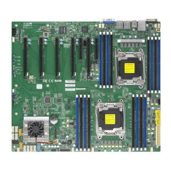
Checklist Congratulations on purchasing your computer motherboard from an acknowledged leader in the industry. Supermicro boards are designed with the utmost attention to detail to provide you with the highest standards in quality and performance. The X10DRG-Q motherboard was designed to be used with a Supermicro-proprie- tary chassis as an integrated server platform. - Page 10 X10DRG-Q Motherboard User’s Manual X10DRG-Q Motherboard Image Note: All graphics shown in this manual were based upon the latest PCB Revision available at the time of publishing of the manual. The motherboard you've received may or may not look exactly the same as the graphics...
- Page 11 Chapter 1: Overview X10DRG-Q Motherboard Layout USB 0/1 LAN2 LAN1 USB 4/5(3.0) LED1 COM1 FAND FANC CTRL BIOS IPMI_LAN LEDM1 CPU2 CLOSE 1st OPEN 1st IPMI CODE BIOS MAC CODE LICENSE BAR CODE X10DRG-Q Rev.1.01 CPU1 CLOSE 1st JBAT1 OPEN 1st JBT1 USB 6 (3.0)
- Page 12 X10DRG-Q Motherboard User’s Manual X10DRG-Q Quick Reference LAN1 USB 0/1 USB 4/5(3.0) LAN2 LED1 COM1 FAND FANC CTRL BIOS IPMI_LAN LEDM1 CPU2 CLOSE 1st OPEN 1st IPMI CODE BIOS MAC CODE LICENSE BAR CODE X10DRG-Q Rev.1.01 CPU1 CLOSE 1st JBAT1...
- Page 13 Chapter 1: Overview X10DRG-Q Jumpers Jumper Description Default Setting JBT1 Clear CMOS See Chapter 2 JHD_AC1 AC'97/HD (High Definition) Audio Select On (HD Enabled) C1/JI C2 System Management Bus (I C) to PCI-E Slots Pins 1-2 (Normal) JPAC1 Front Panel Audio Enable...
- Page 14 Be sure to connect the 24-pin and the 8-pin power connectors to your power supply for adequate power delivery to your system. The 4-pin power connector is optional; however, Supermicro recommends that this connector also be plugged in for optimal power delivery.
-
Page 15: Motherboard Features
Chapter 1: Overview Motherboard Features • Dual Intel® E5-2600v3/v4 Series processors (Socket R3) (LGA 2011); each processor supports dual full- width Intel® QuickPath Interconnect (QPI) links (of up to 9.6 GT/s one direction per QPI) Note: E5-2600v4 requires Revision 2.0 BIOS (or higher). -
Page 16: Peripheral Devices
X10DRG-Q Motherboard User’s Manual I/O Devices SATA Connections • SATA Ports Ten (10) SATA 3.0 ports • I-SATA 0-3 • I-SATA 4/5 (SuperDOM sup- port) • S-SATA 0-3 • RAID RAID 0, 1, 5, 10 IPMI 2.0 • IPMI 2.0 supported by Aspeed AST2400 Serial (COM) Port •... - Page 17 Chapter 1: Overview • Power-on mode for AC power recovery • Intel® Intelligent Power Node Manager 3.0 (Available when the SPM utility is installed and special power supply is used.) • Management Engine (ME) System System Health/CPU Monitoring Health Moni- •...
-
Page 18: System Block Diagram
X10DRG-Q Motherboard User’s Manual JPCIE8 JPCIE11 32GB/s Slot 8 Slot 11 PCIE 3.0 x16 PCIE 3.0 x8 VR12.5 6 PHASE JLAN1 160W JPCIE6 32GB/s RJ45 Dual LAN Slot 6 JLAN2 I350AM2 PCIE 3.0 x16 RJ45 To BMC RMIII port NC - SI... -
Page 19: Processor And Chipset Overview
Processor and Chipset Overview Built upon the functionality and capability of the Intel® E5-2600v3/v4 Series processors (Socket R3) and the Intel® PCH C612, the X10DRG-Q motherboard provides the best balanced solution of performance, power-efficiency, and features to address the diverse needs of next-generation computer users. -
Page 20: Special Features
X10DRG-Q Motherboard User’s Manual Special Features Recovery from AC Power Loss The Basic I/O System (BIOS) provides a setting that determines how the system will respond when AC power is lost and then restored to the system. You can choose for the system to remain powered off (in which case you must press the power switch to turn it back on), or for it to automatically return to the power-on state. -
Page 21: Acpi Features
It is even more important for processors that have high CPU clock rates. The X10DRG-Q motherboard accommodates ATX 24-pin, 12V 8-pin, and 12V 4-pin power connectors. Although most power supplies generally meet the specifications required by the CPU, some are inadequate. In addition, two 8-pin power connections and one 4-pin power connection are also required to ensure adequate power sup- ply to the system. -
Page 22: Advanced Power Management
X10DRG-Q Motherboard User’s Manual Advanced Power Management The following new advanced power management features are supported by this motherboard: Intel Intelligent Power Node Manager (NM) (Available ® when the SPM Utility is Installed) The Intel® Intelligent Power Node Manager 3.0 (IPNM) provides your system with real-time thermal control and power management for maximum energy efficiency. -
Page 23: Chapter 2 Installation
The following statements are industry-standard warnings, provided to warn the user of situations which have the potential for bodily injury. Should you have questions or experience difficulty, contact Supermicro's Technical Support department for assis- tance. Only certified technicians should attempt to install or configure components. - Page 24 X10DRG-Q Motherboard User’s Manual Attention Danger d'explosion si la pile n'est pas remplacée correctement. Ne la remplacer que par une pile de type semblable ou équivalent, recommandée par le fabricant. Jeter les piles usagées conformément aux instructions du fabricant. ¡Advertencia! Existe peligro de explosión si la batería se reemplaza de manera incorrecta.
-
Page 25: Product Disposal
Chapter 2: Installation Product Disposal Warning! Ultimate disposal of this product should be handled according to all national laws and regulations. 製品の廃棄 この製品を廃棄処分する場合、 国の関係する全ての法律 ・ 条例に従い処理する必要が あります。 警告 本产品的废弃处理应根据所有国家的法律和规章进行。 警告 本產品的廢棄處理應根據所有國家的法律和規章進行。 Warnung Die Entsorgung dieses Produkts sollte gemäß allen Bestimmungen und Gesetzen des Landes erfolgen. -
Page 26: Static-Sensitive Devices
X10DRG-Q Motherboard User’s Manual القىانين واللىائح الىطنية جميع وفقا ل ينبغي التعامل معه هذا المنتج من التخلص النهائي عند 경고! 이 제품은 해당 국가의 관련 법규 및 규정에 따라 폐기되어야 합니다. Waarschuwing De uiteindelijke verwijdering van dit product dient te geschieden in overeenstemming met alle nationale wetten en reglementen. -
Page 27: Motherboard Installation
FANC CTRL BIOS IPMI_LAN LEDM1 CPU2 CLOSE 1st OPEN 1st IPMI CODE BIOS MAC CODE LICENSE BAR CODE X10DRG-Q Rev.1.01 CPU1 CLOSE 1st JBAT1 OPEN 1st JBT1 USB 6 (3.0) USB 2/3 FANB AUDIO_FP JVR1 JSPDIF_IN1 Caution: 1) To avoid damaging the motherboard and its components, please do not use a force greater than 8 lb/inch on each mounting screw during motherboard installation. -
Page 28: Installing The Motherboard
X10DRG-Q Motherboard User’s Manual Installing the Motherboard 1. Install the I/O shield into the chassis. 2. Locate the mounting holes on the motherboard. 3. Locate the matching mounting holes on the chassis. Align the mounting holes on the motherboard against the mounting holes on the chassis. -
Page 29: Processor And Heatsink Installation
CPU socket cap is in place and none of the socket pins are bent; otherwise, contact your retailer immediately. • Refer to the Supermicro website for updates on CPU support. Installing the LGA2011 Processor 1. There are two load levers on the LGA2011 socket. To open the socket cover, first press and release the load lever labeled 'Open 1st'. - Page 30 X10DRG-Q Motherboard User’s Manual 2. Press the second load lever labeled 'Close 1st' to release the load plate that covers the CPU socket from its locking position. Pull lever away from Press down on Load the socket Lever 'Close 1st' 3.
- Page 31 Chapter 2: Installation 1. Use your thumb and the index finger to loosen the lever and open the load plate. 2. Using your thumb and index finger, hold the CPU on its edges. Align the CPU keys, which are semi-circle cutouts, against the socket keys. Socket Keys CPU Keys 3.
- Page 32 X10DRG-Q Motherboard User’s Manual 4. With the CPU inside the socket, inspect the four corners of the CPU to make sure that the CPU is properly installed. 5. Close the load plate with the CPU inside the socket. Lock the lever labelled 'Close 1st' first, then lock the lever labelled 'Open 1st' second.
-
Page 33: Installing A Passive Cpu Heatsink
Chapter 2: Installation Installing a Passive CPU Heatsink 1. Do not apply any thermal grease to the heatsink or the CPU die -- the re- quired amount has already been applied. 2. Place the heatsink on top of the CPU so that the four mounting holes are aligned with those on the Motherboard and the Heatsink Bracket underneath. -
Page 34: Removing The Heatsink
X10DRG-Q Motherboard User’s Manual Removing the Heatsink Warning: We do not recommend that the CPU or the heatsink be removed. However, if you do need to uninstall the heatsink, please follow the instructions below to uninstall the heatsink to prevent damage done to the CPU or the CPU socket. -
Page 35: Installing And Removing The Memory Modules
Chapter 2: Installation Installing and Removing the Memory Modules Note: Check Supermicro's website for recommended memory modules. CAUTION Exercise extreme care when installing or removing DIMM modules to prevent any possible damage. Installing Memory Modules 1. Insert the desired number of DIMMs into the memory slots, starting with P1-DIMMA1. - Page 36 X10DRG-Q Motherboard User’s Manual Memory Support for the X10DRG-Q Motherboard The X10DRG-Q motherboard supports up to 2048 GB of 288-pin Load Reduced (LRDIMM) or 512 GB or Registered (RDIMM) DDR4 ECC 2400/2133/1866/1600 MHz in 16 slots. For the latest memory updates, please refer to our website at http:// www.supermicro.com/products/motherboard.
- Page 37 Chapter 2: Installation Populating RDIMM/LRDIMM DDR4 Memory Modules for the E5- 2600v4-based Motherboard Speed (MT/s); Voltage (V); Slot Per Channel (SPC) and DIMM Per Channel (DPC) DIMM Capacity Ranks Per 1 Slot Per (GB) DIMM and 2 Slots Per Channel Channel Type Data...
-
Page 38: Control Panel Connectors And I/O Ports
X10DRG-Q Motherboard User’s Manual Control Panel Connectors and I/O Ports The I/O ports are color coded in conformance with the industry standards. See the picture below for the colors and locations of the various I/O ports. Back Panel Connectors and I/O Ports... -
Page 39: Video Connection
Pin# Definition located on the I/O backplane. These P2V5SB SGND Ethernet ports support Gigabit LAN TD0+ Act LED connections on the X10DRG-Q. In TD0- P3V3SB addition, an IPMI_Dedicated LAN is TD1+ Link 100 LED located above USB ports 4/5 on the (Yellow, +3V3SB) backplane. -
Page 40: Universal Serial Bus (Usb)
X10DRG-Q Motherboard User’s Manual Universal Serial Bus (USB) Two USB 3.0 ports (USB 4/5) and two USB 2.0 ports (USB 0/1) are located on the I/O backpanel. In addition, two internal USB headers provide two USB 3.0 connec- tions (USB 7/8) and two USB 2.0 connections (USB 2/3) for front panel support. A Type A USB 3.0 connector (USB 6) are also located on the motherboard for front... -
Page 41: Uid Led Indicator
2. Front UID LED Header FAND FANC CTRL BIOS IPMI_LAN LEDM1 CPU2 CLOSE 1st OPEN 1st IPMI CODE BIOS MAC CODE LICENSE BAR CODE X10DRG-Q Rev.1.01 CPU1 CLOSE 1st JBAT1 OPEN 1st JBT1 USB 6 (3.0) USB 2/3 FANB AUDIO_FP JVR1 JSPDIF_IN1 2-19... -
Page 42: Serial Ports
X10DRG-Q Motherboard User’s Manual Serial Ports Serial COM) Ports Pin Definitions Two COM connections (COM1 & Pin # Definition Pin # Definition COM2) are located on the mother- board. COM1 is located on the I/O Back panel. COM2, located next to CPU1 PCI-E Slot2, provides front access support. -
Page 43: Front Control Panel
These connectors are designed spe- cifically for use with Supermicro's chassis. See the figure below for the descriptions of the control panel buttons and LED indicators. Refer to the following section for descriptions and pin definitions. -
Page 44: Front Control Panel Pin Definitions
X10DRG-Q Motherboard User’s Manual Front Control Panel Pin Definitions NMI Button NMI Button Pin Definitions (JF1) The non-maskable interrupt button Pin# Definition header is located on pins 19 and 20 Control of JF1. Refer to the table on the right Ground for pin definitions. -
Page 45: Hdd/Uid Led
Chapter 2: Installation HDD/UID LED HDD LED Pin Definitions (JF1) The HDD LED connection is located Pin# Definition on pins 13 and 14 of JF1. Attach a UID LED cable here to indicate HDD activity HD Active and UID status. See the table on the right for pin definitions. -
Page 46: Overheat (Oh)/Fan Fail/Uid Led
X10DRG-Q Motherboard User’s Manual Overheat (OH)/Fan Fail/UID LED OH/Fan Fail/ PWR Fail/Blue_UID LED Pin Definitions (JF1) Connect an LED cable to pins 7 Pin# Definition and 8 of Front Control Panel to use Blue_UID LED the Overheat/Fan Fail and UID LED OH/Fan Fail/Power Fail connections. -
Page 47: Reset Button
Chapter 2: Installation Reset Button Reset Button Pin Definitions (JF1) The Reset Button connection is located on pins Pin# Definition 3 and 4 of JF1. Attach it to a hardware reset Reset switch on the computer case. Refer to the table Ground on the right for pin definitions. -
Page 48: Connecting Cables
X10DRG-Q Motherboard User’s Manual Connecting Cables Power Connectors ATX Power 24-pin Connector Pin Definitions (JPW1) A 24-pin ATX main power supply con- Pin# Definition Pin # Definition nector (JPWR1), two 8-pin CPU power +3.3V +3.3V connectors (JPWR2, JPWR3), and a -12V +3.3V... -
Page 49: Fan Headers
LED1 COM1 FAND FANC CTRL BIOS IPMI_LAN LEDM1 CPU2 CLOSE 1st OPEN 1st IPMI CODE BIOS MAC CODE LICENSE BAR CODE X10DRG-Q Rev.1.01 CPU1 CLOSE 1st JBAT1 OPEN 1st JBT1 USB 6 (3.0) USB 2/3 FANB AUDIO_FP JVR1 JSPDIF_IN1 2-27... -
Page 50: Internal Speaker
X10DRG-Q Motherboard User’s Manual Internal Speaker Internal Buzzer Pin Definition The Internal Speaker (SP1) provides Pin# Definitions audible indications for various beep Pin 1 Pos. (+) Beep In codes. See the table on the right for Pin 2 Neg. (-) Alarm Speaker pin definitions. -
Page 51: I-Sgpio1/2 & S-Sgpio Headers
LED1 COM1 FAND FANC CTRL BIOS IPMI_LAN LEDM1 CPU2 CLOSE 1st OPEN 1st IPMI CODE BIOS MAC CODE LICENSE BAR CODE X10DRG-Q Rev.1.01 CPU1 CLOSE 1st JBAT1 OPEN 1st JBT1 USB 6 (3.0) USB 2/3 FANB AUDIO_FP JVR1 JSPDIF_IN1 2-29... -
Page 52: Chassis Intrusion
X10DRG-Q Motherboard User’s Manual Chassis Intrusion Chassis Intrusion Pin Definitions A Chassis Intrusion header is located Pin# Definition at JL1 on the motherboard. Attach an Intrusion Input appropriate cable from the chassis to Ground inform you of a chassis intrusion when the chassis is opened. -
Page 53: Power Smb (I C) Connector
FAND FANC C. JSD2 CTRL BIOS LEDM1 IPMI_LAN CPU2 CLOSE 1st OPEN 1st IPMI CODE BIOS MAC CODE LICENSE BAR CODE X10DRG-Q Rev.1.01 CPU1 CLOSE 1st JBAT1 OPEN 1st JBT1 USB 6 (3.0) USB 2/3 FANB AUDIO_FP JVR1 JSPDIF_IN1 2-31... -
Page 54: Front Accessible Audio Header
X10DRG-Q Motherboard User’s Manual Front Accessible Audio Header 10-in Audio Pin Definitions A 10-pin Audio header (AUDIO_FP) is located on Pin# Signal the motherboard. This header allows you to use Microphone_Left the onboard sound for audio playback. Connect Audio_Ground an audio cable to this audio header to use this Microphone_Right feature. -
Page 55: Jumper Settings
FANC CTRL BIOS A. GLAN1/2 Enable IPMI_LAN LEDM1 CPU2 CLOSE 1st OPEN 1st IPMI CODE BIOS MAC CODE LICENSE BAR CODE X10DRG-Q Rev.1.01 CPU1 CLOSE 1st JBAT1 OPEN 1st JBT1 USB 6 (3.0) USB 2/3 FANB AUDIO_FP JVR1 JSPDIF_IN1 2-33... -
Page 56: Cmos Clear
X10DRG-Q Motherboard User’s Manual CMOS Clear JBT1 is used to clear CMOS. Instead of pins, this "jumper" consists of contact pads to prevent accidental clearing of CMOS. To clear CMOS, use a metal object such as a small screwdriver to touch both pads at the same time to short the connection. -
Page 57: Vga Enable
BMC Enabled FAND FANC CTRL BIOS LEDM1 IPMI_LAN CPU2 CLOSE 1st OPEN 1st IPMI CODE BIOS MAC CODE LICENSE BAR CODE X10DRG-Q Rev.1.01 CPU1 CLOSE 1st JBAT1 OPEN 1st JBT1 USB 6 (3.0) USB 2/3 FANB AUDIO_FP JVR1 JSPDIF_IN1 2-35... -
Page 58: Ac'97/Hd Select
X10DRG-Q Motherboard User’s Manual AC'97/HD Select AC'97/HD Audio Select Jumper Settings Jumper JHC_AC1 allows you to select High- Jumper Setting Definition Definition (HD) audio or AC'97 audio. The HD Audio (Default) default setting is on to use HD audio the con- AC'97 nection. -
Page 59: I 2 C Bus To Pci-Exp. Slots
LED1 COM1 FAND FANC CTRL BIOS IPMI_LAN LEDM1 CPU2 CLOSE 1st OPEN 1st IPMI CODE BIOS MAC CODE LICENSE BAR CODE X10DRG-Q Rev.1.01 CPU1 CLOSE 1st JBAT1 OPEN 1st JBT1 USB 6 (3.0) USB 2/3 FANB AUDIO_FP JVR1 JSPDIF_IN1 2-37... -
Page 60: Onboard Led Indicators
X10DRG-Q Motherboard User’s Manual Onboard LED Indicators LAN 1/2 Link LED Activity LED LAN LEDs The LAN ports are located on the IO Back- Rear View (when facing the plane on the motherboard. Each Ethernet rear side of the chassis) LAN port has two LEDs. - Page 61 Chapter 2: Installation MAC CODE BAR CODE X10DRG-Q Rev.1.01 2-39...
-
Page 62: 2-10 Sata Connections
X10DRG-Q Motherboard User’s Manual 2-10 SATA Connections SATA 3.0 Ports SATA Connectors Pin Definitions There are ten SATA 3.0 (I-SATA 0-5 & S-SATA0-3) on Pin# Signal the motherboard. I-SATA ports are supported by the Ground Intel PCH C612, and S-SATA ports are supported by SATA_TXP the Intel SCU chip. -
Page 63: Chapter 3 Troubleshooting
Chapter 3: Troubleshooting Chapter 3 Troubleshooting Troubleshooting Procedures Use the following procedures to troubleshoot your system. If you have followed all of the procedures below and still need assistance, refer to the "Technical Support Procedures" and/or "Returning Merchandise for Service" section(s) in this chapter. Note: Always disconnect the power cord before adding, changing or install- ing any hardware components. -
Page 64: System Boot Failure
X10DRG-Q Motherboard User’s Manual No Video 1. If the power is on, but you have no video, remove all the add-on cards and cables. 2. Use the speaker to determine if any beep codes exist. Refer to Appendix A for details on beep codes. -
Page 65: Memory Errors
2. Memory support: Make sure that the memory modules are supported by test- ing the modules using memtest86 or a similar utility. Note: Refer to the product page on our website http:\\www.supermicro. com for memory and CPU support and updates. - Page 66 X10DRG-Q Motherboard User’s Manual within the normal range. Also check the front panel Overheat LED, and make sure that the Overheat LED is not on. 5. Adequate power supply: Make sure that the power supply provides adequate power to the system. Make sure that all power connectors are connected.
-
Page 67: Technical Support Procedures
Technical Support Procedures Before contacting Technical Support, please take the following steps. Also, please note that as a motherboard manufacturer, Supermicro also sells motherboards through its channels, so it is best to first check with your distributor or reseller for troubleshooting services. -
Page 68: Battery Removal And Installation
X10DRG-Q Motherboard User’s Manual Battery Removal and Installation Battery Removal To remove the onboard battery, follow the steps below: 1. Power off your system and unplug your power cable. 2. Locate the onboard battery as shown below. 3. Using a tool such as a pen or a small screwdriver, push the battery lock out- wards to unlock it. -
Page 69: Frequently Asked Questions
Note : The SPI BIOS chip used on this motherboard cannot be removed. Send your motherboard back to our RMA Department at Supermicro for repair. For BIOS Recovery instructions, please refer to the AMI BIOS Recovery Instructions posted at http://www.supermicro.com. -
Page 70: Returning Merchandise For Service
X10DRG-Q Motherboard User’s Manual Returning Merchandise for Service A receipt or copy of your invoice marked with the date of purchase is required before any warranty service will be rendered. You can obtain service by calling your ven- dor for a Returned Merchandise Authorization (RMA) number. When returning the... -
Page 71: Chapter 4 Bios
BIOS Introduction This chapter describes the AMI BIOS Setup utility for the X10DRG-Q. It also pro- vides the instructions on how to navigate the AMI BIOS Setup utility screens. The AMI ROM BIOS is stored in a Flash EEPROM and can be easily updated. -
Page 72: How To Change The Configuration Data
<F2> at the appropriate time during system boot. Note: For AMI UEFI BIOS Recovery, please refer to the UEFI BIOS Recov- ery User Guide posted @ http://www.supermicro.com/support/manuals/. Starting the Setup Utility Normally, the only visible Power-On Self-Test (POST) routine is the memory test. - Page 73 This item displays the system date in Day MM/DD/YY format (e.g. Wed 10/12/2011). System Time This item displays the system time in HH:MM:SS format (e.g. 15:32:52). Supermicro X10DRG-Q BIOS Version This item displays the version of the BIOS ROM used in this system.
-
Page 74: Advanced Setup Configurations
X10DRG-Q Motherboard User’s Manual Advanced Setup Configurations Use the arrow keys to select Advanced Setup and press <Enter> to access the following submenu items. Boot Features Quiet Boot This feature selects the bootup screen display between POST messages and the OEM logo. Select Disabled to display the POST messages. Select Enabled to display the OEM logo instead of the normal POST messages. -
Page 75: Power Configuration
Chapter 4: AMI BIOS Interrupt 19 Capture Interrupt 19 is the software interrupt that handles the boot disk function. When this item is set to Enabled, the ROM BIOS of the host adaptors will "capture" Interrupt 19 at bootup and allow the drives that are attached to these host adaptors to func- tion as bootable disks. -
Page 76: Cpu Configuration
X10DRG-Q Motherboard User’s Manual CPU Configuration This submenu displays the information of the CPU as detected by the BIOS. It also allows the user to configuration CPU settings. Socket 1 CPU Information/Socket 2 CPU Information This submenu displays the following information regarding the CPU installed in Socket 1 and (or) Socket 2 as detected by the BIOS. - Page 77 Chapter 4: AMI BIOS Execute Disable Bit Capability (Available if supported by the OS & the CPU) Select Enabled to enable the Execute-Disable Bit which will allow the processor to designate areas in the system memory where an application code can execute and where it cannot, thus preventing a worm or a virus from flooding illegal codes to overwhelm the processor or damage the system during an attack.
-
Page 78: Advanced Power Management Configuration
X10DRG-Q Motherboard User’s Manual Intel ® Virtualization Technology (Available when supported by the CPU) Select Enabled to support Intel ® Virtualization Technology, which will allow one platform to run multiple operating systems and applications in independent parti- tions, creating multiple "virtual" systems in one physical computer. The options are Enabled and Disabled. -
Page 79: Chipset Configuration
Chapter 4: AMI BIOS CPU C State Control Package C State limit This feature allows the user to set the limit on the C-State package register. The options are C0/C1 State, C2 State, C6 (Non Retention) State, and C6 (Rententioin) State. CPU C3 Report Select Enabled to allow the BIOS to report the CPU C3 State (ACPI C2) to the operating system. - Page 80 X10DRG-Q Motherboard User’s Manual IIO1 Configuration / IIO2 Configuration II01 PORT 1A Link Speed This item configures the link speed of a PCI-E port specified by the user. The options are Gen 1 (Generation 1) (2.5 GT/s), Gen 2 (Generation 2) (5 GT/s) and Gen 3 (Generation 3) (8 GT/s).
- Page 81 Chapter 4: AMI BIOS ® IOAT (Intel IO Acceleration) Configuration Enable IOAT Select Enable to enable Intel I/OAT (I/O Acceleration Technology) support, which significantly reduces CPU overhead by leveraging CPU architectural improve- ments and freeing the system resource for other tasks. The options are Enable and Disable.
-
Page 82: Memory Configuration
X10DRG-Q Motherboard User’s Manual • Current QPI Link Frequency • QPI Global MMIO Low Base/Limit • QPI Global MMIO High Base/Limit • QPI PCIe Configuration Base/Size Link Frequency Select Use this item to select the CPU Frequency. The options are 6.4 GB/s, 8.0 GB/s, 9.6 GB/s, Auto, Auto Limited. -
Page 83: Dimm Information
Chapter 4: AMI BIOS Data Scrambling Select Enabled to enable data scrambling to enhance system performance and data integrity. The options are Auto, Disabled and Enabled. DRAM RAPL Baseline Use this feature to set the run-time power-limit baseline for DRAM modules. The options are Disable, DRAM RAPL Mode 0, and DRAM RAPL Mode 1. -
Page 84: South Bridge Configuration
X10DRG-Q Motherboard User’s Manual Memory Rank Sparing Select Enable to enable memory-sparing support for memory ranks to improve memory performance. The options are Disabled and Enabled. Patrol Scrub Patrol Scrubbing is a process that allows the CPU to correct correctable memory errors detected on a memory module and send the correction to the requestor (the original source). - Page 85 Chapter 4: AMI BIOS XHCI Hand-Off This is a work-around solution for operating systems that do not support XHCI (Ex- tensible Host Controller Interface) hand-off. The XHCI ownership change should be claimed by the XHCI driver. The settings are Enabled and Disabled. EHCI Hand-Off This item is for operating systems that do not support Enhanced Host Controller Interface (EHCI) hand-off.
-
Page 86: Sata Configuration
X10DRG-Q Motherboard User’s Manual Azalia Select Enabled to enable support for Azalia High Definition Audio. The options are Disabled, Enabled, and Auto. Azalia PME Enable Select Enabled to enable power management capability of the Azalia controller. The settings are Enabled and Disabled. - Page 87 Chapter 4: AMI BIOS Port 0 ~ Port 5 Hot Plug Select Enabled to enable hot-plugging support for a port specified by the user, which will allow the user to replace a SATA disk drive installed on this port without shutting down the system.
-
Page 88: Ssata Configuration
X10DRG-Q Motherboard User’s Manual • Model number of drive and capacity • Software Preserve Support Port 0~ Port 5 Select Enabled to enable a SATA port specified by the user. The options are Disabled and Enabled. Port 0 ~ Port 5 Hot Plug... - Page 89 Chapter 4: AMI BIOS Support Aggressive Link Power Management When this item is set to Enabled, the SATA AHCI controller manages the power usage of the SATA link. The controller will put the link to a low power state when the I/O is inactive for an extended period of time, and the power state will return to normal when the I/O becomes active.
- Page 90 X10DRG-Q Motherboard User’s Manual *If the item above "Configure sSATA as" is set to RAID, the following items will display: Support Aggressive Link Power Management When this item is set to Enabled, the SATA AHCI controller manages the power usage of the SATA link. The controller will put the link to a low power state when the I/O is inactive for an extended period of time, and the power state will return to normal when the I/O becomes active.
- Page 91 Chapter 4: AMI BIOS Server ME (Management Engine) Configuration This feature displays the following system ME configuration settings. • General ME Configuration • Operational Firmware Version • Recovery Firmware Version • ME Firmware Features • ME Firmware Status #1 • ME Firmware Status #2 •...
- Page 92 X10DRG-Q Motherboard User’s Manual Maximum Read Request Select Auto for the system BIOS to automatically set the maximum size for a read request for a PCI-E device to enhance system performance. The options are Auto, 128 Bytes, 256 Bytes, 512 Bytes, 1024 Bytes, 2048 Bytes, and 4096 Bytes.
-
Page 93: Super Io Configuration
Chapter 4: AMI BIOS VGA Priority Use this item to select the graphics device to be used as the primary video display for system boot. The options are Onboard and Offboard. Network Stack Select Enabled to enable PXE (Preboot Execution Environment) or UEFI (Uni- fied Extensible Firmware Interface) for network stack support. -
Page 94: Serial Port Console Redirection
X10DRG-Q Motherboard User’s Manual Serial Port Console Redirection COM 1 COM 1 Console Redirection Select Enabled to enable COM Port 1 Console Redirection, which will allow a client machine to be connected to a host machine at a remote site for networking. The options are Disabled and Enabled. - Page 95 Chapter 4: AMI BIOS Stop Bits A stop bit indicates the end of a serial data packet. Select 1 Stop Bit for standard serial data communication. Select 2 Stop Bits if slower devices are used. The options are 1 and 2. Flow Control Use this item to set the flow control for Console Redirection to prevent data loss caused by buffer overflow.
- Page 96 X10DRG-Q Motherboard User’s Manual SOL/COM2 Console Redirection Select Enabled to use the SOL port for Console Redirection. The options are Enabled and Disabled. *If the item above set to Enabled, the following items will become available for user's configuration: SOL/COM2 Console Redirection Settings Use this feature to specify how the host computer will exchange data with the client computer, which is the remote computer used by the user.
- Page 97 Chapter 4: AMI BIOS Flow Control Use this feature to set the flow control for Console Redirection to prevent data loss caused by buffer overflow. Send a "Stop" signal to stop sending data when the receiving buffer is full. Send a "Start" signal to start data-sending when the receiving buffer is empty.
-
Page 98: Acpi Settings
X10DRG-Q Motherboard User’s Manual Terminal Type Use this feature to select the target terminal emulation type for Console Redirec- tion. Select VT100 to use the ASCII character set. Select VT100+ to add color and function key support. Select ANSI to use the extended ASCII character set. - Page 99 Chapter 4: AMI BIOS ® Thunderbolt Intel The following Thunderbolt information will be displayed: • Intel ® Thunderbolt Configuration • Thunderbolt Specification Version • Intel ® Sample Code Version • Thunderbolt Host Chip Intel® Thunderbolt Technology Use this feature to enable or disable the wake-up feature on a Thunderbolt device. The options are Disabled and Enabled.
- Page 100 X10DRG-Q Motherboard User’s Manual SwSMI Support Select Enabled to enable software SMI support in ASL code. The options are En- abled and Disabled. Notify Support Select Enabled to enable notification support in ASL code. The options are Enabled and Disabled.
-
Page 101: Event Logs
Chapter 4: AMI BIOS Event Logs Use this feature to configure Event Log settings. Change SMBIOS Event Log Settings This feature allows the user to configure SMBIOS Event settings. Enabling/Disabling Options SMBIOS Event Log Select Enabled to enable SMBIOS (System Management BIOS) Event Logging during system boot. -
Page 102: View Smbios Event Log
X10DRG-Q Motherboard User’s Manual SMBIOS Event Log Standard Settings Log System Boot Event Select Enabled to log system boot events. The options are Disabled and Enabled. MECI (Multiple Event Count Increment) Enter the increment value for the multiple event counter. Enter a number between 1 to 255. -
Page 103: Ipmi
Chapter 4: AMI BIOS IPMI Use this feature to configure Intelligent Platform Management Interface (IPMI) settings. IPMI Firmware Revision This item indicates the IPMI firmware revision used in your system. IPMI Status This item indicates the status of the IPMI firmware installed in your system. System Event Log ... -
Page 104: Bmc Network Configuration
X10DRG-Q Motherboard User’s Manual When SEL is Full This feature allows the user to determine what the BIOS should do when the sys- tem event log is full. Select Erase Immediately to erase all events in the log when the system event log is full. The options are Do Nothing and Erase Immediately. -
Page 105: Security Settings
Chapter 4: AMI BIOS Gateway IP Address This item displays the Gateway IP address for this computer. This should be in decimal and in dotted quad form (i.e., 192.168.10.253). When you have completed the system configuration changes, select this option to save the changes and reboot the computer so that the new system configuration settings can take effect. -
Page 106: Boot Settings
X10DRG-Q Motherboard User’s Manual User Password Use this feature to set the user password which is required to enter the BIOS setup utility. The length of the password should be from 3 characters to 20 char- acters long. Boot Settings... - Page 107 Chapter 4: AMI BIOS • Dual Boot Order #3 • Dual Boot Order #4 • Dual Boot Order #5 • Dual Boot Order #6 • Dual Boot Order #7 • Dual Boot Order #8 • Dual Boot Order #9 • Dual Boot Order #10 •...
-
Page 108: Save & Exit
X10DRG-Q Motherboard User’s Manual Network Drive BBS Priorities • Legacy Boot Order #1 - Legacy Boot Order #3 UEFI Application Boot Priorities • UEFI Boot Order #1 Save & Exit Select the Save & Exit tab from the BIOS setup screen to configure the settings below. -
Page 109: Configuring Superdoctor 5
X10DRG-Q Motherboard User’s Manual B-2 Configuring SuperDoctor 5 The Supermicro SuperDoctor® 5 is a hardware monitoring program that functions in a command-line or web-based interfaces. The program monitors system health information such as CPU temperature, system voltages, system power consump- tion, fan speed, and provides alerts via email or Simple Network Management Protocol (SNMP). -
Page 110: Appendix C Uefi Bios Recovery Instructions
Flashing the wrong BIOS can cause irreparable damage to the system. In no event shall Supermicro be liable for direct, indirect, special, incidental, or consequential damages arising from a BIOS update. If you need to update the BIOS, do not shut down or reset the system while the BIOS is updating to avoid possible boot failure. - Page 111 Root "\" Directory of a USB device or a writeable CD/DVD. Note: If you cannot locate the "Super.ROM" file in your driver disk, visit our website at www.supermicro.com to download the BIOS image into a USB flash device and rename it "Super.ROM" for BIOS recovery use.
- Page 112 Appendix C: UEFI BIOS Recovery 4. After locating the new BIOS binary image, the system will enter the BIOS Recovery menu as shown below. Note: At this point, you may decide if you want to start with BIOS recovery. If you decide to proceed with BIOS recovery, follow the procedures below. 5.
- Page 113 X10DRG-Q Motherboard User’s Manual 6. After the process of BIOS recovery is completed, press any key to reboot the system. 7. Using a different system, extract the BIOS package into a bootable USB flash drive. 8. When a DOS prompt appears, enter FLASH.BAT BIOSname.### at the prompt.
-
Page 114: Appendix D Dual Boot Block
Appendix D: Dual Boot Block Appendix D Dual Boot Block D-1 Introduction This motherboard supports the Dual Boot Block feature, which is the last-ditch mechanism to recover the BIOS boot block. This section provides an introduction to the feature. BIOS Boot Block A BIOS boot block is the minimum BIOS loader required to enable necessary hardware components for the BIOS crisis recovery flash that will update the main BIOS block. -
Page 115: D-2 Steps To Reboot The System By Using Jumper Jbr1
X10DRG-Q Motherboard User’s Manual D-2 Steps to Reboot the System by Using Jumper JBR1 1. Power down the system. 2. Close pins 2-3 on Jumper JBR1, and power on the system. 3. Follow the BIOS recovery SOP listed in the previous chapter (Appendix C). - Page 116 (Disclaimer Continued) The products sold by Supermicro are not intended for and will not be used in life support systems, medical equipment, nuclear facilities or systems, aircraft, aircraft devices, aircraft/emergency com- munication devices or other critical systems whose failure to perform be reasonably expected to result in significant injury or loss of life or catastrophic property damage.
Need help?
Do you have a question about the X10DRG-Q and is the answer not in the manual?
Questions and answers