
Related Manuals for senseFly EBEE RTK


Summary of Contents for senseFly EBEE RTK
- Page 1 Extended User Manual eBee RTK Revision 3 / December 2014 Copyright © 2010-2015 senseFly Ltd...
- Page 2 flight, damage due to loss of data radio connection, damage due to strong wind, rain or humidity, or other causes for which senseFly Ltd has no control.
- Page 3 ANY OTHER OBLIGATION ON THE PART OF SENSEFLY LTD. Limitation of liability TO THE EXTENT PERMITTED BY APPLICABLE LAW, IN NO EVENT WILL SENSEFLY LTD BE LIABLE FOR ANY LOSS OF REV- ENUE, LOSS OF PROFIT, LOSS OF DATA, OR INDIRECT, SPECIAL, INCIDENTAL OR CONSEQUENTIAL DAMAGES, EVEN IF...
- Page 4 Route de Gen ` e ve 38 1033 Cheseaux-Lausanne Switzerland Website: http://www.sensefly.com Technical support If you have questions about any of your senseFly products: • Try our Knowledge Base. You can find it within my.senseFly (http://my.sensefly.com). • Send an email to support@sensefly.com.
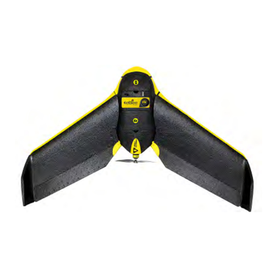
- Page 5 Welcome to your eBee RTK Congratulations on your purchase of the eBee RTK, a complex and powerful yet intuitive autonomous mapping system. We take great care to develop and design the best possible hardware and software tools for quick, high-quality and easy-to- use 2D and 3D aerial mapping.
- Page 6 Note: This manual refers to version 2.4 of eMotion and version 3.2 of Postflight Terra 3D software. The eBee RTK requires eMotion 2.4. If you installed eMotion before purchasing your drone, check the ver- sion and upgrade if necessary. You can consult the Release Notes for...
- Page 7 Package contents user manual eBee RTK battery packs spare propeller eBee RTK battery charger GNSS antenna, remote control, cables and propeller attachment bands eBee RTK battery charger power adapter ground camera modem charger camera glue wing wing eBee central body...
- Page 8 Depending on your order, your package may also include other items, such as additional payloads. Please verify upon delivery that your package is complete. In case of a missing item, please contact your eBee RTK reseller immediately. Caution: The built-in GNSS receiver in the eBee RTK makes it heavier than the standard eBee.
- Page 9 Note: Some of the operating modes of the eBee RTK require a GNSS/RTK base station or access to a subscription-based Ntrip stream. These are not provided in the eBee RTK package. Note: Camera user manuals are also available to download from our ∗...
- Page 10 The eBee RTK is an autonomous flying drone comprised of the following compo- nents: • Central body: This is the core of the eBee RTK and includes all the electron- ics, actuators and communications hardware on-board the drone. • Wing: The two wings of the eBee RTK are detachable for storage and re- placement.
- Page 11 • Data Link Antenna: Used by the drone to communicate with the eMotion software through the USB ground modem. • Pitot probe: This is the sensor used by the eBee RTK to detect airspeed, wind and altitude. It must be kept clean and clear of obstructions to func-...
- Page 12 • Status LED: This coloured LED displays the current state of the eBee RTK. It is housed underneath the pitot probe and thus illuminates the entire trans- parent probe in various colours depending on the drone’s state. • Ground sensor: The ground sensor, composed of a high-speed optical...
- Page 13 flight and send commands if desired. Once your eBee RTK returns after an aerial mapping flight it is the turn of Postflight Terra 3D to process the captured images fully automatically. Postflight Terra 3D is...
-
Page 15: Table Of Contents
Using a local base station ..... Using your eBee RTK with a virtual reference broadcaster ..Using your eBee RTK in standalone mode ... . . 4 Executing a flight... - Page 16 Preparing the eBee RTK for flight ....The setup phase of a flight .....
- Page 17 Flight Parameters tab ..... . . 136 8 Manual control of the eBee RTK Enabling manual control ..... . 140 Pre-flight testing of the remote control .
- Page 18 9 Maintenance and repair of the eBee RTK Updating the eBee RTK software ....148 Cleaning and storage ......150 Full airframe and sensor inspection .
-
Page 19: Quick Start Guide
Part I Quick start guide The first part of this document introduces you to the eBee RTK and contains the basic information you will need to plan and execute a simple mapping project. A typical mapping project can be divided into three main phases: 1. -
Page 20: Planning And Simulating A Flight
first time you can find the drivers in one of the following directories (depend- ing on your version of Windows): C:\Program Files\senseFly\eMotion 2\usb driver\ C:\Program Files (x86)\senseFly\eMotion 2\usb driver\ See section ‘Updating the eBee RTK software’ on page 148 if you have any difficulty with software installation. -
Page 21: The Emotion Interface
1.2 The eMotion interface Thanks to the powerful tools available within eMotion, designing a mapping flight for your eBee RTK is a simple process. To get started, launch eMotion and choose what you would like to do... • To run a simulation, select the simulator, choose the drone you want to simulate and click OK. - Page 22 Panel Map Area Sidebar side the symbol, indicating important status information including the eBee RTK’s current altitude (both Above the Take-off Altitude, marked as ATO, and Above Mean Sea Level, marked as AMSL), battery level, flight time, and status. The Status Panel can be hidden by clicking on the drone.
- Page 23 Planning and simulating a flight eBee RTK while it is in flight, such as starting the mission phase or hold- ing position. It is also used to display and acknowledge warnings that may occur either before or during a flight.
- Page 24 Standalone Use to create maps and DSMs when high relative precision is enough or when RTK corrections are unnecessary or unavailable. Take only the eBee RTK, ground modem and computer and come back with high-quality DSMs and orthomosaics.
-
Page 25: Creating A New Flight Plan
72 for more information on waypoints and the various symbols presented in the Map Area. A complete flight plan for an eBee RTK is divided into two separate phases: the setup phase and the mission phase. The mission phase includes waypoints and actions related to mapping and capturing images. -
Page 26: The Mission Phase Of A Flight
Quick start guide 1.4 The mission phase of a flight The easiest way to create a mapping flight for the systematic coverage of an area is to use the automatic mission planning feature of eMotion. By simply positioning a rectangle around the area you would like to cover, eMotion will generate a mission plan optimised for the ground resolution that you desire. - Page 27 Planning and simulating a flight 2. Adjust the location, size, and shape of the mission area. The area can be relocated by dragging the gray zone. The four square handles on the edges of the area can be used to resize it and the round handles on the corners of the area can be used to rotate it.
-
Page 28: Simulating Your Flight
The final step after you have prepared a flight plan is to save it to a file that you can load into the eBee RTK when you are in the field. Select the Setup Phase tab from the Sidebar, click on ‘Save flight plan to file... ’ , choose a filename and location and click ‘Save’... -
Page 29: Getting Ready For A Mission
Status status LEDs To charge an eBee RTK battery pack, connect it to the battery charger as illustrated above. During charge, the status LED on the charger is solid red. Charging is com- plete when the status LED turns green. - Page 30 Quick start guide If any of the cells is unbalanced, its associated LED will flash red during charging until it is re-balanced. Charging can take up to an hour, depending on the charge level of the battery and the required cell balancing work. See section ‘Proper bat- tery care’...
-
Page 31: Setting Up Rtk
RTCM-compliant base stations from leading brands, checked for non-standard features that might cause incompatibility, and has thus validated them for use with the eBee RTK and eMotion. Some base station manufacturers also make available proprietary data transmis- sion protocols, and senseFly has used these to develop additional base-eMotion automation features for some of these bases. - Page 32 Quick start guide Step 1 Connect your base station to the computer on which you installed eMo- tion following your base station manufacturer’s instructions. The way you connect depends on your base station make and model. eMotion will ac- cept, for example, serial and USB connections. Step 2 Click RTK Setup on the eMotion toolbar.
-
Page 33: Setting Up Reference Points For Your Gnss/Rtk Base Station
Note that the eBee RTK internal GNSS receiver transforms the GLONASS ellipsoid (PZ-90) into WGS 84. You can set up several reference points in eMotion. Once in the field you can then quickly change base station position using the Choose RTK Source menu. -
Page 34: Setting Up Virtual Reference Broadcasters
Quick start guide Note: If you have access to reference station files, it is not essential to have the precise coordinates of your base station. Your eBee RTK logs its position relative to the base station with a high degree of preci- sion (using RTK corrections). - Page 35 Setting up RTK Step 5 Enter the port number on which the broadcaster is streaming. This is of- ten port 2101 (set by default), however, the caster device may be stream- ing on a different port. Check with the broadcaster to confirm. Step 6 If you are connecting to a stream that requires registration or subscrip- tion, enter your user name and password.
-
Page 36: Using Rtk
Quick start guide 3 Using RTK Choose the source of your RTK corrections using the menu on the eMotion toolbar. The message RTK Source Not Defined appears until you either choose a source or choose to fly standalone. Set Up RTK Choose RTK Source RTK Status The status of your RTK corrections, directly from your base station, or indirectly... - Page 37 Using RTK If your Base Station’s Position is Known: Step 3 Choose Above known reference point. Step 4 Enter the height above ground of your base station. Step 5 Select the reference point. Step 6 Click Finish. A base station icon ( ) appears on your map at the reference point coordinates.
- Page 38 Quick start guide If your Base Station’s Position is Unknown or Imprecise: Step 3 Choose Above unknown point. Step 4 Click Set Position Now to take coordinates from the connected base sta- tion. Step 5 Click Finish. A base station icon ( ) appears on your map at the base station’s coordinates.
-
Page 39: Using Your Ebee Rtk With A Virtual Reference Broadcaster
Using RTK 3.2 Using your eBee RTK with a virtual reference broadcaster Step 1 From the eMotion Choose RTK Source menu, select the VRS/Ntrip service you want to connect to for your flight. Step 2 If a VRS is created, a base station icon ( ) appears on your map at its coordinates. -
Page 40: Executing A Flight
RTK in flight. 4.1 Weather check Before each flight, you should be aware of the weather conditions. The eBee RTK is a small drone that cannot fly in heavy rain or strong wind conditions. In case of doubt, make sure to check a weather bulletin including wind estimations in the flight area. -
Page 41: Preparing The Ebee Rtk For Flight
4.2 Preparing the eBee RTK for flight The eBee RTK’s simple design means it can go from the box to being ready for flight in minutes. We recommend that you perform the following 6 steps before every flight to ensure that the platform is best prepared for flight. - Page 42 Note: A general inspection should be performed before every flight. It is also good practice to perform a full airframe check regularly to keep your eBee RTK in good shape. See section ‘Full airframe and sen- sor inspection’ on page 151 for more details.
- Page 43 Executing a flight motor motor propeller propeller attachment rubber bands Step 2: Install the propeller Mount the propeller on the motor axis. Secure the propeller using two attach- ment rubber bands as illustrated above. Ensure that the propeller is lying flat against the motor mount, and that the rubber bands do not show cracks or any other sign of aging.
- Page 44 Step 3: Install the camera Install the camera into the payload bay⁶ within the eBee RTK and close the camera compartment lid. If the camera connector is not already connected, plug it into the connector with the icon on the eBee RTK.
- Page 45 Executing a flight insert wing struts into central body ensure servo connection mechanism is aligned and engaged Step 4: Attach the wings Attach the wings to the central body by inserting the wing struts into the re- ceptacles in the central body. Ensure that the ailerons are properly aligned with the servo connection mechanism before pushing the wings fully into the central body.
- Page 46 Step 5: Install and connect the battery Lay the eBee RTK horizontally on the ground outside in the vicinity of the take- off location, with the top face up. To install the battery, begin by connecting the power cables to the battery. Insert the connectors firmly to the end in order to avoid undesired disconnection when in flight.
- Page 47 During the pre-flight checks the status LED will pulse blue. Once the pre-flight checks are complete the eBee RTK will flip its ailerons up and down and the status LED will turn solid green to indicate it is ready. You may already connect the drone to eMotion (Step 6) before pre-flight checks are complete to get a better idea of...
- Page 48 When a connection is established eMotion will display a map and the Status Panel indicating the current state of the drone. If the eBee RTK has not yet detected its location the Status Panel will appear in the top right corner of the Map Area with the text ‘GPS/GLONASS: Waiting for signals...
- Page 49 Executing a flight You can now load a flight plan you prepared earlier by selecting the Setup Phase tab from the Sidebar, clicking on ‘Load flight plan from file... ’ and selecting your flight plan file. Alternatively, you can plan the entire mission in the field, following the same process outlined in section ‘Planning and simulating a flight’...
-
Page 50: The Setup Phase Of A Flight
4.3 The setup phase of a flight The setup phase of a flight includes the waypoints and actions related to the take- off and landing of the eBee RTK and includes the following locations: • Take-off location: The point from which the drone is launched, automati- cally set to the location calculated from GPS/GLONASS signals by the drone when it is launched. - Page 51 The Home waypoint is used both as the landing location and as a safety position in case of an In-flight warning. The eBee RTK can perform either a Linear or a Circular landing. Linear landing is the default and recommended landing type, especially in high winds.
- Page 52 If these conditions are not met the drone cannot ensure a touch- down against the direction of the wind. Landing in the direction of the wind in strong-wind conditions may result in a high landing speed and damage to the eBee RTK.
- Page 53 Executing a flight To prepare a Circular landing, place the Home waypoint in a location that has no obstacles within a radius of 50 m (or 20 m more than the Home waypoint radius) to give the drone enough space to land. Ensure that the entire landing area is flat to allow the ground sensor to function properly.
-
Page 54: Take-Off
4.4 Take-off Once you’ve planned your mission and the eBee RTK status LED is solid green you can launch it using the procedure on the following pages. Caution: Make sure to keep the propeller area free of all obstructions at all times during the launch procedure. - Page 55 Step 2: Switch the motor on Shake the eBee RTK back and forth 3 times longitudinally (within approx. 3 sec- onds) to begin the motor power-up sequence. The status LED will pulse blue until the motor is at full power and ready for take-off.
- Page 56 ¹¹ see section ‘Flight Parameters tab’ on page 136 to change this parameter ¹² The eBee RTK may also be programmed to wait at the Start waypoint for a command before starting its mapping mission. See section ‘Setup Phase tab’ on page 116 for more information.
-
Page 57: In-Flight Monitoring And Control
flight. A small arrow and infobox show the speed and direc- tion of the wind as measured by the eBee RTK. The Status Panel that follows the position of the drone displays basic flight information including battery charge, flight time and altitude, both above the take-off... - Page 58 The estimated area captured on the ground is displayed in the form of a continuously-updating polygon in the Map Area. Note: The eBee RTK will not take a picture unless it is in the cor- rect location and altitude. Some reasons for not taking an image are strong head wind, large off-track distance or incorrect altitude.
-
Page 59: Landing
flight data after each flight (see section ‘Im- porting images and flight data’ on page 61) before putting the eBee RTK back in its case for storage. When disconnecting the wings, be sure to pull gently in the axis of the wing struts to prevent damage to the wing struts. - Page 60 Critical failure until the moment it reaches the ground. Its position’s coordinates can aid in finding it afterwards. Instructions on how to find a lost drone can be found in section ‘Losing and locating your eBee RTK in the field’ on page 180.
-
Page 61: Processing Image Data
Geoid-Ellipsoid Separation. 5.2 Importing images and flight data The next step to creating mapping products, after completing a flight, is to im- port the raw images and log files to a computer. The eBee RTK records flight data... - Page 62 The file is required for assigning location information (geotags) to the im- ages taken by the drone. The file is also required and must be sent to senseFly Ltd in case an issue occurred during the flight¹⁴. A similar eMotion Flight Log file is created within eMotion during a flight and serves as a backup in case the Drone...
- Page 63 RTK corrections, gathered from the Ntrip broadcast, to your drone and your drone was logging the precise coordinates of each image it took. If you flew your eBee RTK in standalone mode, you do not have any RTK cor- rections; all the flight data you need is stored onboard your drone.
- Page 64 • Step 3 - Prepare data for import: To import the Drone Flight Log, connect the supplied USB cable to the eBee RTK’s autopilot, marked with a icon. Connect the battery to the drone if it is not already connected. The status LED will become white and a new storage drive will appear on your com- puter.
- Page 65 Processing image data • Step 6 - import RTK correction files: Note: You will only see this step if you used a local base station. If you used a base station with a known position • Choose The base was placed over a known point. Click Next to continue. If you don’t need to make any modifications, click Next again.
- Page 66 Quick start guide 3. Choose the file format and enter the path to the file, or click Browse and locate the files. 4. Enter the paths to your reference station RINEX observation and navigation files, or click Browse to locate the file on your computer. Once complete, click Next to continue.
-
Page 67: In-Field Image Quality Check
Postflight Terra 3D for further processing. 5.3 In-field image quality check Postflight Terra 3D software¹⁵, available as a free download with the eBee RTK pack- age, can be used to rapidly create a Quality Report directly in the field. The Quality Report that is automatically generated as well as the orthomosaic provide imme- diate feedback on the quality of the images gathered during your mission. - Page 68 Quick start guide Automatic Reconstruction Report generation Top Toolbar Project Summary Layers Local Processing panel Map Area Step 1: select 1. Initial Processing, Rapid Check Step 2: click ‘Start’ To create a Quality Report while in the field bring up the local processing panel by selecting ‘Local processing’...
-
Page 69: Creating Advanced Mapping Products
File menu. Note: The best way to learn how to use the various features of Post- flight Terra 3D is to look at the comprehensive online Knowledge Base within my.senseFly¹⁷ 5.5 Transforming coordinates First, set up the latitude/longitude to x/y transformation... - Page 70 Quick start guide Step 2 If you know the coordinate system name, click From List and choose the one you want. If you know the EPSG code of your coordinate system, click From EPSG and choose the code you want. If you have the .prj coordinate system syntax file, click From .prj, browse to the location of your file, select the file and click Open.
-
Page 71: Advanced Functionalities
Part II Advanced functionalities... -
Page 72: Understanding Aerial Mapping With The Ebee Rtk
flight. 6.1 Waypoints and their properties The eBee RTK uses a flight plan consisting of a list of waypoints to navigate. A waypoint essentially consists of a circle about a given position and information that defines how the drone should behave when reaching them. - Page 73 Understanding aerial mapping with the eBee RTK can store up to 50 mission waypoints. Setup phase waypoints (Start and Home) do not have an ID. • Active: Indicates whether the waypoint is active or not. Deactivating a waypoint by clicking the checkbox beside its ID will remove it from the cur- rent flight plan.
- Page 74 (clockwise or counter-clockwise). • Radius: The distance at which the drone circles around the waypoint. Note: The eBee RTK has a limited turning radius. Setting this parame- ter lower than 20 m may cause the drone to significantly deviate from its desired flight path.
- Page 75 Understanding aerial mapping with the eBee RTK If a waypoint’s Auto-next parameter is disabled, the path directly after it will be dashed, indicating that a command must be sent for the flight to continue. Clicking a waypoint in the Map Area will display its characteristics (waypoint ID for mission waypoints or name for setup waypoints, altitude, radius and action) and will select it for modification.
- Page 76 Advanced functionalities • Altitude: Hold down the ‘Ctrl’ button while left-clicking on the waypoint and moving the mouse up or down to increase or decrease the altitude of the waypoint, respectively. • Create new waypoint: Right-click anywhere in the Map Area that does not contain a symbol to bring up the context menu, then select ‘Add waypoint here’...
-
Page 77: Advanced Polygonal Mission Area
Understanding aerial mapping with the eBee RTK 6.2 Advanced polygonal mission area The mission area defines the area of interest where the eBee RTK will take pho- tos. It appears as a grey rectangle when you select the ‘Mission planning’ tab and to calculate the flight plan of the drone. -
Page 78: Mission Planning Using Elevation Data
Toolbar. eMo- tion’s default Improved SRTM elevation data will be downloaded as tiles from senseFly’s servers and overlaid above the map as a colourmap¹⁹. You can adjust the scale and opacity of the colourmap by using the associated buttons in the bottom-right corner of the Map Area. - Page 79 Understanding aerial mapping with the eBee RTK Activate the 3D mission planning feature by selecting the ‘Use elevation data to set absolute waypoint altitudes’ parameter in the ‘Mission Planning’ tab. Elevation data is used to adjust every mission waypoint altitude as follows: 1.
-
Page 80: Flight Visualization In Google Earth
Advanced functionalities Note: It is recommended to visually compare imported elevation datasets with the default Improved SRTM elevation layer of eMotion in order to detect possible mismatches. This comparison should be done with a colourmap opacity value of 100%. More advanced controls of imported datasets are available in the ‘Elevation data’ panel of the Preferences pane of the menu. - Page 81 flight plan and the terrain. ²⁰ While checking flight plans in Google Earth is a good safety practice, senseFly Ltd provides no guarantee regarding the accuracy and completeness of the Google Earth terrain model.
-
Page 82: Autonomous Controller And Modes Of Flight
Manual Position During a typical flight the autonomous controller on the eBee RTK will switch be- tween various modes depending on its flight plan and the commands that it re- ceives from the Control Bar²¹. The controller changes between modes during a typical mission as shown in the figure above, and as described in more detail in... - Page 83 Understanding aerial mapping with the eBee RTK three times initiates the take-off procedure²² and changes to the Take-off mode. • After take-off the drone climbs with level wings²³, gaining altitude until it reaches the take-off transition altitude, by default 20 m²⁴ above the take-off...
- Page 84 • Clicking the ‘LAND NOW’ button in the Control Bar three times in quick suc- cession will cause the drone to initiate a Circular landing procedure at its ²⁵ see section ‘Manual control of the eBee RTK’ on page 140 for information on the various manual control modes ²⁶...
- Page 85 Understanding aerial mapping with the eBee RTK current location with its motor disabled and change to Emergency Land- ing mode.
-
Page 86: Linear Landing
6.6 Linear landing A typical Linear landing follows these steps: 1. The eBee RTK flies towards the Home waypoint (defined by the user within eMotion; default altitude is 75 m above the landing altitude). The altitude change behaviour between the current location and the Home waypoint depends on the ‘Altitude change’... - Page 87 Understanding aerial mapping with the eBee RTK Linear landing procedure, seen from the side Home 1. Aproach Home waypoint waypoint 2. Descend to 75m 4. Fly in calculated direction above landing altitude 3. Circle to measure wind measure wind 5. Glide with controlled...
- Page 88 flat will likely result in false detection of the height above the ground during the approach and may result in damage to the eBee RTK. In particular, landing downhill may cause a large overshoot and should always be...
- Page 89 • In order to limit the ground speed when landing and to achieve the best landing accuracy, the eBee RTK should only perform a Linear landing against the direction of the wind. Approach sectors should be as large as possible and in as many directions as possible to allow the drone to select the opti- mal approach direction based on its estimate of the wind.
- Page 90 Advanced functionalities proach sectors. Do not define approach sectors over low-texture surfaces such as large bodies of water, snow or sand. • During a Linear landing the drone requires sufficient energy to slow down its descent and perform its final brake (Steps 5-7). If the Linear landing op- tion is active and the battery descends below 20% an In-flight warning will appear²⁸...
-
Page 91: Flying Multiple Drones At The Same Time
Understanding aerial mapping with the eBee RTK Note: The eBee RTK’s ground sensor can typically begin detecting ground proximity at a distance of 40 m. If the drone reaches an es- timate altitude of 20 m/ATO (as estimated using the on-board GNSS receiver and pressure sensor) without a signal on its ground sensor it assumes there is a malfunction with the ground sensor. - Page 92 Advanced functionalities drone operation eMotion provides the following: • When more than one drone is connected at a time, a dedicated interface called the Multi-drone panel is displayed to monitor each drone and switch between them. • A number of settings are offered to keep relevant flight configurations (such as the Start and Home waypoint) synchronised between all connected drones.
- Page 93 Understanding aerial mapping with the eBee RTK selected drone second drone connected to this computer drone shared through network Multi-drone panel Sidebar One advantage of flying multiple drone drones at once is to cover more area in less time. eMotion can automatically upload a multi-flight mission to all connected drones in a single click.
- Page 94 Advanced functionalities Clicking on the icon in the Multi-drone panel allows you to either connect a new drone or to bring up the Multi-drones preferences pane. Multi-drone coordination Traffic control Network sharing eMotion provides Multi-drone coordination options to synchronise various way- points and parameters among connected drones: •...
- Page 95 Understanding aerial mapping with the eBee RTK for all connected drones. A stack will also be created to avoid collisions between multiple drones circling the Home waypoint. Caution: As eMotion defines the Start and Home waypoints in ATO. It is therefore critical for all drones to take off from the exact same location to achieve altitude separation and collision avoidance over these two waypoints.
- Page 96 Advanced functionalities Caution: All collision avoidance mechanisms are implemented by eMotion on the ground computer. The drones’ autopilot do not com- municate between themselves and do not have knowledge of each other’s positions. It is therefore critical to keep all drones connected to eMotion at all times and remain well inside communication range.
-
Page 97: Individual Photo Targets And Oblique Imagery
Understanding aerial mapping with the eBee RTK • Share simulators on my local network: If this box is checked, all Network sharing options apply to both real and simulated drones connected to your computer. In unchecked, they only apply to real drones. - Page 98 ‘Begin sequence’ button in the Camera tab at any time to begin taking the images. The eBee RTK will fly to the location of the first photo location, measure the wind above the location, and perform a dive (pitching down) ma- noeuvre to take the oblique photo.
-
Page 99: Emergency Manoeuvres
• Unexpected intrusions into the landing zone. • Birds approaching or attacking your drone. • Unexpected changes in wind conditions. As a precautionary measure to be used only when absolutely necessary, the eBee RTK has been programmed with a series of emergency manoeuvres: • Land now The drone immediately initiates a circular landing around a 30 m radius waypoint at its current location. - Page 100 Advanced functionalities Activating Emergency Manoeuvres The land now and abort landing buttons are always available on the control bar. To activate the roll, fast climb and descent features: 1. Choose Preferences from the File menu. 2. Choose the User interface pane. 3.
- Page 101 Understanding aerial mapping with the eBee RTK When to use the Emergency Manoeuvres You might need to use an emergency manoeuvre in these situations: Presence of birds Birds approach your drone out of curiosity, or they consider it a threat and attack •...
- Page 102 Advanced functionalities Unexpected intrusions into airspace Your drone is about to collide with another aircraft or UAV. Consider a fast climb or descent. Unexpected intrusions into landing zone A person or vehicle moves into your landing zone during landing approach. Con- sider aborting the landing.
-
Page 103: Emotion In-Depth Guide
7 eMotion in-depth guide Goal of this section: eMotion is a powerful tool designed specifically to work with your senseFly mini-drones. This section includes a com- prehensive guide to all the functionalities in eMotion to help you plan, simulate and monitor your next mapping flight. -
Page 104: Toolbar
The main eMotion interface is composed of a Map Area, a Toolbar and a Sidebar³⁰. The Map Area displays the current location of the eBee RTK, a Status Panel with important information on the drone’s current status, and a Control Bar used to send commands to the drone (section ‘Control Bar’... - Page 105 eMotion in-depth guide You can access the File menu by clicking on the button in the Toolbar. From this menu you can connect to or disconnect from a drone, access the Flight Data Man- ager, change eMotion preferences or import custom maps. Clicking the icon will launch Google Earth and display the current flight trajectories of drones con-...
- Page 106 ‘Generate Google Maps tiles and KML’ from the ‘Process’ menu within Postflight Terra 3D. Whenever the eBee RTK takes a picture, eMotion records the location and orienta- tion of the drone and computes the approximate span of the photo on the ground (or ‘footprint’).
-
Page 107: Simulator
The simulated drone will go through the same pre- flight checks as a real eBee RTK, after which it will update the Home to its current position (typically the last position that was used within the simulator) and the... - Page 108 Toolbar and the various tabs of the Sidebar in eMotion to see their effect on the eBee RTK while it is in flight. Also be sure to explore the effects of the vari- ous buttons in the Control Bar on the behaviour of your drone. Don’t be afraid to push the boundaries! Aborting a flight or causing an emergency landing in the...
-
Page 109: Control Bar
Clicking this button will instantly recharge the bat- battery tery of the drone. Note: This is a simulated action that is not possible with the real eBee RTK while it is in flight. Wind speed and These fields are used to input a simulated wind speed direction and direction. - Page 110 Advanced functionalities The Control Bar includes buttons for sending commands to the drone and for ac- knowledging warnings while it is in flight. Certain buttons can only be used dur- ing specific flight modes³². The Command buttons allows the operator to directly control the drone while it is in flight.
- Page 111 eMotion in-depth guide GO LAND Anytime Fly towards the Home waypoint and initiate landing procedure. HOLD No active Create a virtual waypoint at the current loca- POSITION Security action tion and altitude, circle around this point and wait for next command. LAND NOW Anytime Initiate a Circular landing around a 30 m ra-...
-
Page 112: Flight Monitoring Tab
Advanced Instruments The Flight Monitoring tab can be used to monitor the eBee RTK during a mapping mission and is the default tab that is displayed when you click anywhere on the map area that does not have a symbol. The tab is split into the following sections: •... - Page 113 flight, including ground speed and height, altitude Above Mean Sea Level (AMSL) and the absolute position detected by the GNSS receiver on-board the eBee RTK. ³⁴ see section ‘Troubleshooting’ on page 157 ³⁵ see section ‘Proper battery care’ on page 154...
- Page 114 The column on the left displays the current air speed of the eBee RTK as well as the desired air speed, in metres per second. The column on the right displays the drone’s current altitude over take-off lo- cation, as well as the desired altitude over the take-off...
- Page 115 eMotion in-depth guide • Advanced Instruments: This section displays the current internal temper- ature of the drone, the number of GPS/GLONASS signals detected and the estimated accuracy of the the position.
-
Page 116: Setup Phase Tab
Advanced functionalities 7.5 Setup Phase tab Take-off parameters Start waypoint After mission and take-off actions Home waypoint Landing Setup phase reset Flight plan actions The Setup Phase tab is used to define the setup phase of a flight plan. This phase includes the definition of the Home and Start waypoints and the actions to be taken before and after the mission phase of the flight plan. - Page 117 eMotion in-depth guide altitude. To enable this feature, expand the ‘Take-off parameters’ box and check the ‘Activate directional take-off’ check box. A new arrow is now dis- played on the map. This arrow defines the take-off heading, the drone will try to stay on the track defined by the arrow.
- Page 118 • After mission: Use this panel to select the action you wish the drone to execute once it completes the mission phase. The eBee RTK can either au- tomatically go to the Home waypoint and land, go to the Home or Start waypoint and wait for a command or to restart the mission phase.
- Page 119 flight plan (both setup and mission phases) to a XML file for later reuse. You can also save the current flight plan to the eBee RTK’s on-board memory by clicking the ‘Save flight plan in drone’ button. Once a flight plan is saved in the drone’s memory, it will become the default flight...
-
Page 120: Mission Planning Tab
Note: If there is no flight plan overlaid on the mission area rectangle then the mission is too large and cannot be flown by the eBee RTK. This can be for two reasons: either the distance between two way- points is too long for the drone to cover in a single flight, or the way-... - Page 121 eMotion in-depth guide Mapping and mission parameters Advanced parameters Mission plan actions Resulting flight characteristics The Mission Planning tab is divided in several panels. The first panel, Mapping and mission parameters, contains the parameters that define the requirements of a particular mission: •...
- Page 122 Advanced functionalities relatively low image overlap. Note: The preset values are recommended settings that have demonstrated good results when images are then used in Postflight Terra 3D to create orthomosaics. Do not hesitate, however, to mod- ify these parameters to suit the particularities of the terrain you are mapping or the local regulations and airspace constraints.
- Page 123 Note: eBee RTK has a minimum distance between images that de- pends on wind strength and direction. The maximum longitudinal overlap depends on this minimum distance as well as the calculated altitude and the camera model. If the calculated altitude is too low the drone may not be able to achieve the required longitudinal over- lap.
- Page 124 Default value: 1 • Wind estimate: The estimated wind speed and direction. Incorrectly set- ting the windspeed affects the estimated flight time of the eBee RTK and may cause it to return to Home before completing the desired flight plan.
- Page 125 flight individually. Caution: Clicking ‘Upload’ will directly modify the waypoints re- quired for the flight plan in the eBee RTK. If the drone is flying towards or around one of these waypoints, its navigation will be affected to reflect the new waypoint parameters.
- Page 126 Advanced functionalities all mapping and mission parameters to their last saved default values⁴¹. • Restore factory settings: Click to restore all the parameters of this tab to their default settings. The last panel of this tab displays the characteristics of the flight(s) resulting from the selected image parameters: •...
- Page 127 Ground resolution and Camera model parameters. The wind also has an influence as the ground speed increases with back wind. Note: The eBee RTK has a minimum distance between photos that depends on the wind speed and direction. If the calculated distance that is too short will be indicated with a icon.
- Page 128 Advanced functionalities image, based on the Altitude over take-off location parameter (assuming flat terrain). • Number of waypoints: The total number of waypoints to cover the mis- sion area. • Elevation data sources: The elevation data sources being used to calcu- late the altitudes of the waypoints.
-
Page 129: Mission Waypoints Tab
eMotion in-depth guide 7.7 Mission Waypoints tab Selected mission waypoint parameters Remaining mission waypoints Add or reset waypoints The Mission Waypoints tab contains a list of all mission waypoints currently on the drone autopilot. It can be used for finer control of individual waypoints in the current mission. - Page 130 Advanced functionalities Caution: Any change to the waypoints or their parameters are di- rectly sent to the drone and may therefore impact its flight behaviour. We recommend that you take great care before modifying waypoints while the drone is in flight. You can add new waypoints by clicking the button or by right-clicking on the Map Area and selecting ‘Add waypoint here’...
-
Page 131: Camera Tab
eMotion in-depth guide 7.8 Camera tab Camera model Photo sequence control Photo targets Individual photos New photo target increment Camera control Camera parameters for mapping The camera tab is an advanced tab that can be used to precisely control the func- tioning of the camera. - Page 132 Advanced functionalities The ‘Camera model’ section is used to define the camera or payload currently con- nected to the eBee RTK. The list contains all payloads currently supported on the eBee RTK. The ‘Photo targets’ section allows you to program a set of photo targets that the drone will capture with an oblique angle.
- Page 133 eMotion in-depth guide – Pitch: The pitch angle with respect to vertical of the photo target. – Altitude reference: The altitude reference of the photo target alti- tude, either ATO or AMSL. – Target altitude: The altitude of the photo target. –...
- Page 134 The ‘Camera parameters for mapping’ section is used to define detailed parame- ters related to the camera and has the following functions: • Pitch angle: By default the eBee RTK takes images at a default estimated ◦ pitch angle of 7 relative to the horizon.
- Page 135 • Save parameters as default in drone: Saves the currently-set camera pa- rameters to the eBee RTK’s autopilot’s memory. • Restore factory parameters: Returns the parameters to their default val- ues and automatically send them to the drone’s autopilot.
-
Page 136: Flight Parameters Tab
Advanced functionalities 7.9 Flight Parameters tab Flight parameters General information The Flight Parameters tab includes some advanced functions that govern the over- all behaviour of the drone while in flight. It is separated into two sections: ‘Flight parameters’ and ‘General information’ . The ‘Flight parameters’ section includes the following items: •... - Page 137 Security action, however the In-flight warning will continue to appear. Default value: checked ⁴² see section ‘Manual control of the eBee RTK’ on page 140 for more information ⁴³ see section ‘In-flight warnings’ on page 163 for more information on Security actions related to...
- Page 138 Default value: unchecked • Climb in case of detected ground proximity (<30 m): The eBee RTK fea- tures a ground sensor that continuously checks the presence of the ground. If this box is checked and the ground sensor detects a height above the ground of less than 30 m, the drone will climb to a safe height of 60 m be- fore continuing the mission.
- Page 139 flights performed by drone and the total time spent in the air. Note: The flight counter is incremented every time the take-off pro- cedure is initiated by shaking the eBee RTK back and forth 3 times, even if take-off is subsequently aborted.
-
Page 140: Manual Control Of The Ebee Rtk
8.1 Enabling manual control By default, the eBee RTK flies autonomously and does not need the provided re- mote control to be operated. However, by using the remote control, it is possi- ble to override the drone’s autopilot by switching to one of two available manual modes: Full Manual or Assisted Manual. - Page 141 Manual control of the eBee RTK can be achieved at any time if the drone is within range of the remote⁴⁶.
-
Page 142: Pre-Flight Testing Of The Remote Control
8.2 Pre-flight testing of the remote control If you plan to use the remote control during a flight we recommend that you first test it on the ground. Ensure that the eBee RTK is set to Full Manual mode⁴⁷ and follow these steps: 1. -
Page 143: Full Manual Mode
Manual control of the eBee RTK 8.3 Full Manual mode Full Manual mode allows you to have direct control over the eBee RTK’s actua- tors, overriding all control from the on-board autopilot. The left stick controls the thrust. For safety reasons, the left stick should remain at the lowest position at all times, except during flight. -
Page 144: Assisted Manual Mode
Manual mode when in a large open space with no obstacles and low wind. In this mode the left stick is used to set the desired speed of the eBee RTK. Set- ting the left stick between 10% and 100% sets a desired speed between 10.5 and 20 m/s. - Page 145 Assisted Manual mode after completing the standard take-off procedure⁴⁹. Caution: There is no clear indication during the take-off procedure that the eBee RTK will change to Assisted Manual mode rather than Circle Start Waypoint mode after the take-off transition altitude is reached⁵⁰.
- Page 146 Advanced functionalities 7. Once the drone is around 5-10 m from the landing location, cut motor power using the left stick and allow the drone to glide down to the ground.
-
Page 147: Maintenance, Repair And Troubleshooting
Part III Maintenance, Repair and Troubleshooting... -
Page 148: Maintenance And Repair Of The Ebee Rtk
9.1 Updating the eBee RTK software Occasionally, senseFly Ltd releases a software upgrade for the eBee RTK to provide additional features to our users or to correct potential issues. As of version 2.0.2, eMotion will check for new versions during start-up⁵¹ and will display a message with update instructions if a new version is available. - Page 149 1. Connect the battery to the drone. 2. Connect the USB cable between the computer on which you installed eMo- tion and the autopilot of the eBee RTK as shown in the figure. The connector is beside the camera connector and is marked with a icon.
-
Page 150: Cleaning And Storage
Parameters tab once connected (see section ‘Flight Parameters tab’ on page 136). 9.2 Cleaning and storage Use a damp cloth to wipe off dirt from the eBee RTK. In order to avoid structural de- formation of the wing, it is recommended to store the drone either in its transport case or on a flat surface at room temperature. -
Page 151: Full Airframe And Sensor Inspection
The inspection includes the following checks: Check 1: Motor and Servos The eBee RTK uses a brushless DC motor to turn its propeller and generate thrust. The servos are the two actuators connected through a servo connection mech- anism to both ailerons. Damaged actuators can prevent the drone from flying correctly and thus it is important to ensure their proper functioning. - Page 152 RTK’ on page 181 for advice. ⁵⁴ see section ‘Manual control of the eBee RTK’ on page 140 for details on using the remote control ⁵⁵ see section ‘Flight Parameters tab’ on page 136 for more details on these settings...
- Page 153 Flight Monitoring tab of eMotion. To check the inertial sensors, follow these steps: 1. Switch the eBee RTK on by connecting the battery and connect to eMotion. 2. Put the drone on a flat surface (typically an office floor) and check that the artificial horizon is level.
-
Page 154: Repairing The Ebee Rtk Airframe
Expanded Polypropylene (EPP). If you have doubts about the extent of the damage, always contact your eBee RTK reseller to verify if the damage can be eas- ily repaired by yourself or if you need to send your drone in for repair to. - Page 155 flight times in cold weather. The eBee RTK is powered by a Lithium Polymer (LiPo) battery composed of three cells connected in series. A single LiPo cell can have a range between 3 V (empty) and 4.2 V (full) in its normal operating range.
- Page 156 Maintenance, Repair and Troubleshooting Caution: If any of the cells of your battery pack are overly discharged the battery may be irreversibly damaged and becomes dangerous to charge. If the battery grows beyond its regular size or if any of the cells are punctured it is also likely damaged and should be discarded.
-
Page 157: Troubleshooting
flight and provides some tips on solving the simplest problems. In the case of a more serious problem, this section describes how to pre- pare the required data on the problem and report it to your eBee RTK reseller. -
Page 158: Pre-Flight Errors
The start-up process is described in detail in section ‘Preparing the eBee RTK for flight’ on page 41. If an error occurs during these pre-flight checks the status LED will blink red and a description of the error will appear in eMotion. - Page 159 If the problem persists, perform Check 3 in section ‘Full air- frame and sensor inspection’ on page 151. If this does not solve the problem contact your eBee RTK re- seller.
- Page 160 If the problem persists, perform Check 2 in section ‘Full air- frame and sensor inspection’ on page 151. If this does not solve the problem contact your eBee RTK re- seller. Ground sensor There is an error with the drone’s ground sensor.
-
Page 161: Take-Off Vetoes
After successfully completing pre-flight checks the status LED becomes a solid green to indicate that the drone is ready for take-off. At this point the eBee RTK continues to monitor its sensors and battery level. If at any point the drone detects a condition that prevents it from beginning the automatic take-off... - Page 162 ‘Preparing the eBee RTK for flight’ on page 41. USB cable The eBee RTK has detected a USB cable connected to detected the drone’s autopilot. User action: Remove the USB cable before take-off.
-
Page 163: In-Flight Warnings
Troubleshooting 10.3 In-flight warnings While it is in flight the eBee RTK can generate two types of errors: warnings and failures. In-flight warnings occur when there is an event that requires user atten- tion but does not compromise the drone’s ability to continue flying. - Page 164 (failure Critical failure has occurred even if it is no longer ac- description) tive⁵⁷. Security action: The eBee RTK flies towards the Home waypoint at an altitude defined by the Home waypoint’s Change altitude parameter (by default, set to ‘Highest’).
- Page 165 Change altitude parameter (by default, set to ‘Highest’). User action: Land as soon as possible and re-start the drone. If the problem persists, contact your eBee RTK reseller. Camera sync There is a problem with the wiring of the on-board malfunction camera.
- Page 166 Maintenance, Repair and Troubleshooting Camera power The camera is no longer responding, most likely be- malfunction cause it is no longer powered. Security action: If required parameter set in the Flight Parameters tab, the drone flies towards the Home waypoint at an altitude defined by the Home waypoint’s Change altitude parameter (by default, set to ‘Highest’).
- Page 167 Home way- point’s Change altitude parameter (by default, set to ‘Highest’). User action: Land as soon as possible and re-start the drone. If the problem persists, contact your eBee RTK reseller. ⁵⁸ see section ‘Critical failures’ on page 176...
- Page 168 Maintenance, Repair and Troubleshooting Airspeed The differential pressure sensor used to measure air- malfunction speed is registering invalid values. This may be due to a damaged sensor or to a clogged pitot probe. Security action: The drone flies towards the Home waypoint at an altitude defined by the Home way- point’s Change altitude parameter (by default, set to ‘Highest’) at a constant thrust value instead of con-...
- Page 169 The sensor used to detect the presence of the wings malfunction malfunctioning. Security action: The drone continues normal flight. User action: Land as soon as possible and inspect the wing struts as described in section ‘Preparing the eBee RTK for flight’ on page 41.
- Page 170 Maintenance, Repair and Troubleshooting Temperature out The temperature sensor on the drone is registering ◦ of working levels internal temperatures of less than -50 C or more ◦ than 90 C. This may occur in extremely hot or cold environments or if the on-board autopilot is dam- aged.
- Page 171 User action: Keep track of the location of the drone during landing. If the drone lands outside of view fol- low the instructions in section ‘Losing and locating your eBee RTK in the field’ on page 180.
- Page 172 Maintenance, Repair and Troubleshooting Poor GPS/GLONASS signal coverage is low. This may be GPS/GLONASS due to mountains or tall buildings blocking satellite ∗ coverage signals. If coverage degrades any more a Critical fail- ure will be activated and an emergency landing will be initiated⁵⁹.
- Page 173 Troubleshooting ∗∗ Data uplink lost This warning occurs if the eBee RTK does not receive (if enabled) any data from eMotion for more than 30 s. This can be due to a large distance between drone and ground station, a problem with the USB ground modem, an- tenna positioning or interference.
- Page 174 User action: Add a new approach sector against the direction of the wind, if possible, abort the landing and try landing again. If not, be ready for the eBee RTK to overshoot its planning Linear landing location by preparing a larger obstacle-free zone around the lo- cation.
- Page 175 Troubleshooting ∗ Strong wind The wind is too strong for the eBee RTK to navigate safely. Security action (if enabled): The eBee RTK flies to- wards the Home waypoint at an altitude defined by the Home waypoint’s Change altitude parameter (by default, set to ‘Highest’).
-
Page 176: Critical Failures
flight. This is the most serious type of error that can occur with the eBee RTK, and is indicated in red in eMotion. The ‘WARNING’ button in the Control Bar changes to ‘CRITICAL FAILURE’ , becomes red and cannot be acknowledged. - Page 177 Troubleshooting last known position in the air and in eMotion if possible and follow the instructions in section ‘Losing and locating your eBee RTK in the field’ on page 180. Table 6: Critical failures eMotion text Description and Emergency action...
- Page 178 Maintenance, Repair and Troubleshooting Failure: motor The motor is not working even after an attempted malfunction re-start commanded by a Motor malfunction In-flight warning. Emergency action: The drone orients itself in the di- rection of the Home waypoint and glides towards the ground while continuously trying to re-start the mo- tor.
-
Page 179: Resetting Default Camera Settings
30 s you will see a ‘Data uplink lost’ In-flight warning appear in eMotion. If for safety reasons you would like the eBee RTK to automatically return to the Home waypoint when this warning appears, select the corresponding option in the Flight Parameters tab⁶⁴. -
Page 180: Losing And Locating Your Ebee Rtk In The Field
10.7 Losing and locating your eBee RTK in the field We recommend that you write your address and phone number on your eBee RTK (by putting your business card on top of the camera for example) in case it gets lost and subsequently found by a third party. -
Page 181: Reporting A Problem With Your Ebee Rtk
Troubleshooting 10.8 Reporting a problem with your eBee RTK If there is a problem with your eBee RTK, whether it is a software malfunction, damaged airframe or any other problem, we recommend the following actions: 1. If there is an error message displayed in eMotion, begin by checking section ‘Troubleshooting’... -
Page 183: Specifications
Part IV Specifications... -
Page 184: Software Requirements
Specifications 1 Software requirements eMotion has the following minimum software requirements: Operating system Windows XP / Vista / 7 / 8 Hardware 1.6 GHz processor 2 GB RAM 500 MB free storage space Screen recommended resolution: 1920×1080 visible outdoors Postflight Terra 3D has the following minimum software requirements: Operating system Windows XP / Vista / 7 / 8, 64-bit only Hardware... -
Page 185: Drone Specifications
Troubleshooting 2 Drone specifications Size Wingspan: 96 cm Wing area: 0.25 m Weight without camera and battery approx. 0.46 kg Nominal take-off weight (approx.) 0.73 kg (1.61 lbs) (with standard camera & battery) Material EPP foam, carbon structure & compos- ite parts Battery 3-cell Lithium-Polymer (0.14 kg) - Page 186 Specifications Communication devices Ground modem: • Frequency: 2.4 GHz • Range⁷⁰: approx. 3 kmUp to 3 km (1.9 miles) • Certification: FCC Part 15.247, IC RSS210, CE Remote control: • Frequency: 2.4 GHz • Range: approx. 1 km • Certification: CE, FCC Navigation Up to 50 waypoints GSD (per pixel)
-
Page 187: Onboard Gnss/Rtk Receiver
Troubleshooting 3 Onboard GNSS/RTK receiver Number of channels Signal tracked GPS: L1, L2 GLONASS: L1, L2 Onboard RTK correction 20 Hz Upstream correction 1 Hz RTK data transmission protocols RTCM-3.x, RTCM-2.x Acquisition time Hot start: <10 s Warm start: <35 s Cold start: <60 s Reacquisition: <1 s... - Page 188 Specifications Glossary AMSL Above Mean Sea Level Your eBee RTK’s altitude can be shown and set in eMotion using ATO or AMSL. Your drone uses the EGM96 mean sea level standard for navigation. ATO Above the Take-off Altitude Your eBee RTK’s altitude can be shown and set in eMotion using ATO or AMSL.
- Page 189 Troubleshooting or DSM. The smaller the GSD, the higher the spatial resolution of the image. For example, a GSD of 5 cm means that one pixel in the image represents 5 cm on the ground. mosaic A single map or terrain model created from several map sections that have been placed side-by-side and merged together.
- Page 190 Specifications RPAS Remotely Piloted Aircraft System A term used for drones or UAVs, the software and technology they use to navigate. RTCM Radio Technical Commission for Maritime Services An international organisation that standardises transmission protocols that allow for RTK positioning, for example, RTCM 2.x and RTCM 3.x. They also publish the Ntrip standard.
Need help?
Do you have a question about the EBEE RTK and is the answer not in the manual?
Questions and answers