
Subscribe to Our Youtube Channel
Related Manuals for senseFly eBee


Summary of Contents for senseFly eBee
- Page 1 Extended User Manual eBee and eBee Ag Revision 12 / September 2014 Copyright © 2010-2014 senseFly Ltd...
- Page 2 flight, damage due to loss of data radio connection, damage due to strong wind, rain or humidity, or other causes for which senseFly Ltd has no control.
- Page 3 ANY OTHER OBLIGATION ON THE PART OF SENSEFLY LTD. Limitation of liability TO THE EXTENT PERMITTED BY APPLICABLE LAW, IN NO EVENT WILL SENSEFLY LTD BE LIABLE FOR ANY LOSS OF REV- ENUE, LOSS OF PROFIT, LOSS OF DATA, OR INDIRECT, SPECIAL, INCIDENTAL OR CONSEQUENTIAL DAMAGES, EVEN IF...
- Page 4 Address senseFly Ltd Route de Gen ` e ve 38 1033 Cheseaux-Lausanne Switzerland Website: http://www.sensefly.com Technical support If you have questions on your eBee or accompanying software please consult senseFly Ltd’s Technical support website at the following address: http://www.sensefly.com/support/...
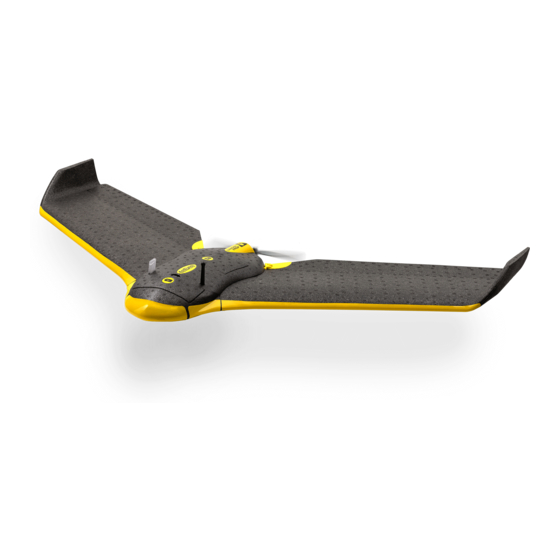
- Page 5 Welcome to your eBee Congratulations on your purchase of the eBee, a complex and powerful yet intu- itive autonomous mapping system. We take great care to develop and design the best possible hardware and software tools for quick, high-quality and easy-to-use 2D and 3D aerial mapping.
- Page 6 Package contents User manual eBee battery battery packs charger spare propeller remote control, cables and propeller eBee attachment battery bands charger cable ground camera modem charger camera glue wing eBee wing central body...
- Page 7 Depending on your order, your package may also include other items, such as additional payloads. Please verify upon delivery that your package is complete. In case of a missing item, please contact your eBee reseller immediately. Note: Camera user manuals are also available to download from...
- Page 8 The eBee is an autonomous flying drone comprised of the following components: • Central body: This is the core of the eBee and includes all the electronics, actuators and communications hardware on-board the drone. • Wing: The two wings of the eBee are detachable for storage and replace- ment.
- Page 9 • Data Link Antenna: Used by the drone to communicate with the eMotion software through the USB ground modem. • Pitot probe: This is the sensor used by the eBee to detect airspeed, wind and altitude. It must be kept clean and clear of obstructions to function properly.
- Page 10 • Ground sensor: The ground sensor, composed of a high-speed optical sensor and lens assembly, is used to detect the proximity of the ground.
- Page 11 ∗ Software access terms and conditions apply. Postflight Terra 3D is limited to eBee images only.
-
Page 13: Table Of Contents
Weather check ......Preparing the eBee for flight .... - Page 14 Advanced functionalities 4 Understanding aerial mapping with the eBee Waypoints and their properties ....Advanced polygonal mission area ....
- Page 15 Assisted Manual mode ..... . . 124...
- Page 16 7 Maintenance and repair of the eBee Updating the eBee software ....128 Cleaning and storage ......131 Full airframe and sensor inspection .
-
Page 17: Quick Start Guide
Part I Quick start guide The first part of this document introduces you to the eBee and contains the basic information you will need to plan and execute a simple mapping project. A typical mapping project can be divided into three main phases: 1. -
Page 18: Planning And Simulating A Flight
1 Planning and simulating a flight Goal of this section: This section introduces the eMotion software used to interface with the eBee. It describes the steps required to plan, simulate, and save a simple mapping flight. A more detailed description of eMotion and its advanced functions is presented in sec- tion ‘eMotion in-depth guide’... -
Page 19: The Emotion Interface
1.2 The eMotion interface Thanks to the powerful tools available within eMotion, designing a mapping flight for your eBee is a simple process. To get started, launch eMotion and choose what you would like to do... • To run a simulation, select the simulator, choose the drone you want to simulate and click OK. - Page 20 A small Status Panel floats be- side the symbol, indicating important status information including the eBee’s current altitude (both Above the Take-off Altitude, marked as ATO, and Above Mean Sea Level, marked as AMSL), battery level, flight time, and status. The Status Panel can be hidden by clicking on the drone.
-
Page 21: Creating A New Flight Plan
Planning and simulating a flight • Control Bar: The Control Bar is used to issue various commands to the eBee while it is in flight, such as starting the mission phase or holding position. It is also used to display and acknowledge warnings that may occur either before or during a flight. -
Page 22: The Mission Phase Of A Flight
Quick start guide in the field and is explained in detail in section ‘The setup phase of a flight’ on page 37. 1.4 The mission phase of a flight The easiest way to create a mapping flight for the systematic coverage of an area is to use the automatic mission planning feature of eMotion. - Page 23 Planning and simulating a flight as size and position is overlaid on the area. A mission plan, including the required waypoints, is automatically calculated and displayed to preview the mission plan that will be created. 2. Adjust the location, size, and shape of the mission area. The area can be relocated by dragging the gray zone.
-
Page 24: Simulating Your Flight
The final step after you have prepared a flight plan is to save it to a file that you can load into the eBee when you are in the field. Select the Setup Phase tab from the Sidebar, click on ‘Save flight plan to file... ’ , choose a filename and location and click ‘Save’... -
Page 25: Getting Ready For A Mission
flight. 1.6 Getting ready for a mission Before leaving for the field to perform a flight, be sure to fully charge all your eBee batteries⁵. When delivered, the eBee battery may not be fully charged. - Page 26 Quick start guide any of the cells is unbalanced, its associated LED will be solid red during charging until it is re-balanced. Charging can take up to an hour, depending on the charge level of the battery and the required cell balancing work. See section ‘Proper bat- tery care’...
-
Page 27: Executing A Flight
flight. 2.1 Weather check Before each flight, you should be aware of the weather conditions. The eBee is a small drone that cannot fly in heavy rain or strong wind conditions. In case of doubt, make sure to check a weather bulletin including wind estimations in the flight area. -
Page 28: Preparing The Ebee For Flight
Quick start guide 2.2 Preparing the eBee for flight The eBee’s simple design means it can go from the box to being ready for flight in minutes. We recommend that you perform the following 6 steps before every flight to ensure that the platform is best prepared for flight. - Page 29 Note: A general inspection should be performed before every flight. It is also good practice to perform a full airframe check regularly to keep your eBee in good shape. See section ‘Full airframe and sensor inspection’ on page 131 for more details.
- Page 30 Quick start guide motor motor propeller propeller attachment rubber bands Step 2: Install the propeller Mount the propeller on the motor axis. Secure the propeller using two attach- ment rubber bands as illustrated above. Ensure that the propeller is lying flat against the motor mount, and that the rubber bands do not show cracks or any other sign of aging.
- Page 31 Step 3: Install the camera Install the camera into the payload bay⁶ within the eBee and close the camera compartment lid. If the camera connector is not already connected, plug it into the connector with the icon on the eBee.
- Page 32 Quick start guide insert wing struts into central body ensure servo connection mechanism is aligned and engaged Step 4: Attach the wings Attach the wings to the central body by inserting the wing struts into the re- ceptacles in the central body. Ensure that the ailerons are properly aligned with the servo connection mechanism before pushing the wings fully into the central body.
- Page 33 Step 5: Install and connect the battery Lay the eBee horizontally on the ground outside in the vicinity of the take-off lo- cation, with the top face up. To install the battery, begin by connecting the power cables to the battery. Insert the connectors firmly to the end in order to avoid un- desired disconnection when in flight.
- Page 34 Pre-flight checks may last from a few seconds to several minutes in the case of poor GPS signal reception. As these satellite signals are required for the checks to complete, be sure to place the eBee outside with a clear view of the sky.
- Page 35 When a connection is established eMotion will display a map and the Status Panel indicating the current state of the drone. If the eBee has not yet detected its loca- tion the Status Panel will appear in the top right corner of the Map Area with the text ‘GPS: Waiting for signals...
- Page 36 Quick start guide You can now load a flight plan you prepared earlier by selecting the Setup Phase tab from the Sidebar, clicking on ‘Load flight plan from file... ’ and selecting your flight plan file. Alternatively, you can plan the entire mission in the field, following the same process outlined in section ‘Planning and simulating a flight’...
-
Page 37: The Setup Phase Of A Flight
2.3 The setup phase of a flight The setup phase of a flight includes the waypoints and actions related to the take- off and landing of the eBee and includes the following locations: • Take-off location: The point from which the drone is launched, automat- ically set to the location calculated from GPS signals by the drone when it is launched. - Page 38 The Home waypoint is used both as the landing location and as a safety position in case of an In-flight warning. The eBee can perform either a Linear or a Circular landing. Linear landing is the default and recommended landing type, especially in high winds.
- Page 39 If these conditions are not met the drone cannot ensure a touch- down against the direction of the wind. Landing in the direction of the wind in strong-wind conditions may result in a high landing speed and damage to the eBee.
- Page 40 Quick start guide To prepare a Circular landing, place the Home waypoint in a location that has no obstacles within a radius of 50 m (or 20 m more than the Home waypoint radius) to give the drone enough space to land. Ensure that the entire landing area is flat to allow the ground sensor to function properly.
-
Page 41: Take-Off
2.4 Take-off Once you’ve planned your mission and the eBee status LED is solid green you can launch it using the procedure on the following pages. Caution: Make sure to keep the propeller area free of all obstructions at all times during the launch procedure. - Page 42 Step 2: Switch the motor on Shake the eBee back and forth 3 times longitudinally (within approx. 3 seconds) to begin the motor power-up sequence. The status LED will pulse blue until the motor is at full power and ready for take-off.
- Page 43 ¹¹ see section ‘Flight Parameters tab’ on page 116 to change this parameter ¹² The eBee may also be programmed to wait at the Start waypoint for a command before starting its mapping mission. See section ‘Setup Phase tab’ on page 96 for more information.
-
Page 44: In-Flight Monitoring And Control
flight. A small arrow and infobox show the speed and direction of the wind as measured by the eBee. The Status Panel that follows the position of the drone displays basic flight information including battery charge, flight time and altitude, both above the take-off... - Page 45 The estimated area captured on the ground is displayed in the form of a continuously-updating polygon in the Map Area. Note: The eBee will not take a picture unless it is in the correct loca- tion and altitude. Some reasons for not taking an image are strong head wind, large off-track distance or incorrect altitude.
-
Page 46: Landing
flight data after each flight (see section ‘Im- porting images and flight data’ on page 48) before putting the eBee back in its case for storage. When disconnecting the wings, be sure to pull gently in the axis of the wing struts to prevent damage to the wing struts. - Page 47 Critical failure until the moment it reaches the ground. Its position’s coordinates can aid in finding it afterwards. Instructions on how to find a lost drone can be found in section ‘Losing and locating your eBee in the field’ on page 159.
-
Page 48: Processing Image Data
The next step to creating mapping products, after completing a flight, is to import the raw images and log files to a computer. The eBee records flight data onboard in a special Drone Flight Log file. The Drone Flight Log tracks important information throughout a flight, such as sensor data, location and control inputs. - Page 49 Processing image data select Flight Data Manager click OK Follow these steps to import data from the drone: • Step 1 - Select a flight: If the flight was monitored from the computer you are using to import images then the flight is saved within the local database.
- Page 50 • Step 3 - Prepare data for import: To import the Drone Flight Log, connect the supplied USB cable to the eBee’s autopilot, marked with a icon. Con- nect the battery to the drone if it is not already connected. The status LED will become white and a new storage drive will appear on your computer.
-
Page 51: In-Field Image Quality Check
Postflight Terra 3D for further processing. 3.2 In-field image quality check Postflight Terra 3D software¹⁵, available as a free download with the eBee package, can be used to rapidly create a Quality Report directly in the field. The Quality Report that is automatically generated as well as the orthomosaic provide imme- diate feedback on the quality of the images gathered during your mission. - Page 52 Quick start guide Automatic Reconstruction Report generation Top Toolbar Project Summary Layers Local Processing panel Map Area Step 1: select 1. Initial Processing, Rapid Check Step 2: click ‘Start’ To create a Quality Report while in the field bring up the local processing panel by selecting ‘Local processing’...
-
Page 53: Creating Advanced Mapping Products
Processing image data 3.3 Creating advanced mapping products Beyond Quality Reports and low-resolution orthomosaics, Postflight Terra 3D can generate geo-referenced high-resolution 2D orthomosaics, 3D point clouds, tri- angle models and DSMs or export to common third-party photogrammetry soft- ware such as Bingo, Orima or Inpho. Ground Control Points (GCP) can be added to increase the geo-reference accuracy. -
Page 55: Advanced Functionalities
Part II Advanced functionalities... -
Page 56: Understanding Aerial Mapping With The Ebee
flight. 4.1 Waypoints and their properties The eBee uses a flight plan consisting of a list of waypoints to navigate. A waypoint essentially consists of a circle about a given position and information that defines how the drone should behave when reaching them. - Page 57 Understanding aerial mapping with the eBee • Active: Indicates whether the waypoint is active or not. Deactivating a waypoint by clicking the checkbox beside its ID will remove it from the cur- rent flight plan. Setup phase waypoints (Start and Home) cannot be deac- tivated.
- Page 58 (clockwise or counter-clockwise). • Radius: The distance at which the drone circles around the waypoint. Note: The eBee has a limited turning radius. Setting this parameter lower than 20 m may cause the drone to significantly deviate from its desired flight path.
- Page 59 Understanding aerial mapping with the eBee and will select it for modification. It will also activate the Mission Waypoints tab and highlight the selected waypoint. Future Flight path Inactive Selected flight path altitude flight path waypoint Current waypoint Current status Traversed flight path...
-
Page 60: Advanced Polygonal Mission Area
field. 4.2 Advanced polygonal mission area The mission area defines the area of interest where the eBee will take photos. It appears as a grey rectangle when you select the ‘Mission planning’ tab and to cal-... -
Page 61: Mission Planning Using Elevation Data
Understanding aerial mapping with the eBee area provides the simplest way to quickly create a flight plan. It can be modified as described in section ‘The mission phase of a flight’ on page 22. For more complex areas eMotion has the option of using polygonal-shaped mis- sions areas. - Page 62 Improved SRTM elevation data will be downloaded as tiles from senseFly Ltd servers and overlaid above the map as a colourmap¹⁸. You can ad- just the scale and opacity of the colourmap by using the associated buttons in the bottom-right corner of the Map Area.
- Page 63 Understanding aerial mapping with the eBee under the current waypoint, the previous waypoint and the flight line that connects the two. 2. This maximum value is increased by the target altitude value, and the result is set as the altitude of the current waypoint.
-
Page 64: Flight Visualization In Google Earth
The flight plan is projected onto the ¹⁹ While checking flight plans in Google Earth is a good safety practice, senseFly Ltd provides no... - Page 65 Understanding aerial mapping with the eBee ground in a darker colour, giving you an idea of the distance between the flight path and the ground. If you connect to a simulated drone you can simulate the entire flight and follow the drone within Google Earth...
-
Page 66: Autonomous Controller And Modes Of Flight
Manual Position During a typical flight the autonomous controller on the eBee will switch between various modes depending on its flight plan and the commands that it receives from the Control Bar²⁰. The controller changes between modes during a typical mission as shown in the figure above, and as described in more detail in the fol-... - Page 67 Understanding aerial mapping with the eBee three times initiates the take-off procedure²¹ and changes to the Take-off mode. • After take-off the drone climbs with level wings²², gaining altitude until it reaches the take-off transition altitude, by default 20 m²³ above the take-off...
- Page 68 • Clicking the ‘LAND NOW’ button in the Control Bar three times in quick suc- cession will cause the drone to initiate a Circular landing procedure at its ²⁴ see section ‘Manual control of the eBee’ on page 120 for information on the various manual control modes ²⁵...
- Page 69 Understanding aerial mapping with the eBee current location with its motor disabled and change to Emergency Land- ing mode.
-
Page 70: Linear Landing
4.6 Linear landing A typical Linear landing follows these steps: 1. The eBee flies towards the Home waypoint (defined by the user within eMo- tion; default altitude is 75 m above the landing altitude). The altitude change behaviour between the current location and the Home waypoint depends on the ‘Altitude change’... - Page 71 Understanding aerial mapping with the eBee Linear landing procedure, seen from the side Home 1. Aproach Home waypoint waypoint 2. Descend to 75m 4. Fly in calculated direction above landing altitude 3. Circle to measure wind measure wind 5. Glide with controlled...
- Page 72 flat will likely result in false detection of the height above the ground during the approach and may result in damage to the eBee. In particular, landing downhill may cause a large overshoot and should always be...
- Page 73 Caution: It is not recommended to perform Linear landings between tall obstacles, as they may disturb the GPS signals your eBee needs to be able to navigate. • In order to limit the ground speed when landing and to achieve the best landing accuracy, the eBee should only perform a Linear landing against the direction of the wind.
- Page 74 Advanced functionalities proach sectors. Do not define approach sectors over low-texture surfaces such as large bodies of water, snow or sand. • During a Linear landing the drone requires sufficient energy to slow down its descent and perform its final brake (Steps 5-7). If the Linear landing op- tion is active and the battery descends below 20% an In-flight warning will appear²⁷...
-
Page 75: Flying Multiple Drones At The Same Time
Understanding aerial mapping with the eBee Note: The eBee’s ground sensor can typically begin detecting ground proximity at a distance of 40 m. If the drone reaches an estimate al- titude of 20 m/ATO (as estimated using the on-board GPS and pres- sure sensor) without a signal on its ground sensor it assumes there is a malfunction with the ground sensor. - Page 76 Advanced functionalities drone operation eMotion provides the following: • When more than one drone is connected at a time, a dedicated interface called the Multi-drone panel is displayed to monitor each drone and switch between them. • A number of settings are offered to keep relevant flight configurations (such as the Start and Home waypoint) synchronised between all connected drones.
- Page 77 Understanding aerial mapping with the eBee selected drone second drone connected to this computer drone shared through network Multi-drone panel Sidebar One advantage of flying multiple drone drones at once is to cover more area in less time. eMotion can automatically upload a multi-flight mission to all connected drones in a single click.
- Page 78 Advanced functionalities Clicking on the icon in the Multi-drone panel allows you to either connect a new drone or to bring up the Multi-drones preferences pane. Multi-drone coordination Traffic control Network sharing eMotion provides Multi-drone coordination options to synchronise various way- points and parameters among connected drones: •...
- Page 79 Understanding aerial mapping with the eBee for all connected drones. A stack will also be created to avoid collisions between multiple drones circling the Home waypoint. Caution: As eMotion defines the Start and Home waypoints in ATO. It is therefore critical for all drones to take off from the exact same location to achieve altitude separation and collision avoidance over these two waypoints.
- Page 80 Advanced functionalities Caution: All collision avoidance mechanisms are implemented by eMotion on the ground computer. The drones’ autopilot do not com- municate between themselves and do not have knowledge of each other’s positions. It is therefore critical to keep all drones connected to eMotion at all times and remain well inside communication range.
-
Page 81: Individual Photo Targets And Oblique Imagery
Understanding aerial mapping with the eBee • Share simulators on my local network: If this box is checked, all Network sharing options apply to both real and simulated drones connected to your computer. In unchecked, they only apply to real drones. - Page 82 ‘Begin sequence’ button in the Camera tab at any time to be- gin taking the images. The eBee will fly to the location of the first photo location, measure the wind above the location, and perform a dive (pitching down) ma- noeuvre to take the oblique photo.
-
Page 83: Emotion In-Depth Guide
5 eMotion in-depth guide Goal of this section: eMotion is a powerful tool designed specifically to work with your senseFly Ltd mini-drones. This section includes a comprehensive guide to all the functionalities in eMotion to help you plan, simulate and monitor your next mapping flight. -
Page 84: Toolbar
The main eMotion interface is composed of a Map Area, a Toolbar and a Sidebar²⁹. The Map Area displays the current location of the eBee, a Status Panel with im- portant information on the drone’s current status, and a Control Bar used to send commands to the drone (section ‘Control Bar’... - Page 85 48), a tile set can be generated for each project that is directly compatible with eMotion. You can therefore create your own map background using the eBee. You can generate the tile set by selecting ‘Generate Google Maps tiles and KML’ from the ‘Process’...
- Page 86 Advanced functionalities ‘footprint’). All the footprints taken by a drone are added to a shaded polygon outlined with the drone’s colour and displayed in the Map Area. This polygon represents an estimate of the area that has been photographed by the drone. The footprints can be shown or hidden using the button.
-
Page 87: Simulator
The simulated drone will go through the same pre- flight checks as a real eBee, after which it will update the Home to its current posi- tion (typically the last position that was used within the simulator) and the Start waypoint to 80 m West of the Home waypoint. - Page 88 flight. Note: this is a simulated action that is not possible with the real eBee. Instead of pausing while in flight we recommend that you use the ‘HOLD POSITION’ function to better simulate real flight conditions.
-
Page 89: Control Bar
Clicking this button will instantly recharge the bat- battery tery of the drone. Note: This is a simulated action that is not possible with the real eBee while it is in flight. Wind speed and These fields are used to input a simulated wind speed direction and direction. - Page 90 Advanced functionalities Table 2: Control Bar Buttons Button Available Action WARNING³² Active For yellow In-flight warnings, button text warning changes to ‘ACK WARNING’ and clicking will acknowledge the current warning. For red Critical failures, button text changes to ‘CRIT- ICAL FAILURE’ and cannot be clicked. START No active Fly towards the first active waypoint in the...
- Page 91 eMotion in-depth guide LAND NOW Anytime Initiate a Circular landing around a 20 m ra- Click 3x dius waypoint at the current location. Must be clicked 3 times in quick succession to be engaged. ABORT During Cir- Circular or Linear landing: abort current LANDING cular Land-...
-
Page 92: Flight Monitoring Tab
Advanced Instruments The Flight Monitoring tab can be used to monitor the eBee during a mapping mis- sion and is the default tab that is displayed when you click anywhere on the map area that does not have a symbol. The tab is split into the following sections: •... - Page 93 flight, including ground speed and height, altitude Above Mean Sea Level (AMSL) and the absolute position detected by the GPS on- board the eBee. ³³ see section ‘Troubleshooting’ on page 137 ³⁴ see section ‘Proper battery care’ on page 135...
- Page 94 The column on the left displays the current air speed of the eBee as well as the desired air speed, in metres per second. The column on the right displays the drone’s current altitude over take-off location, as well as the desired altitude over the take-off...
- Page 95 eMotion in-depth guide • Advanced Instruments: This section displays the current internal temper- ature of the drone, the number of GPS signals detected and the estimated accuracy of the the position.
-
Page 96: Setup Phase Tab
Advanced functionalities 5.5 Setup Phase tab Take-off parameters Start waypoint After mission and take-off actions Home waypoint Landing Setup phase reset Flight plan actions The Setup Phase tab is used to define the setup phase of a flight plan. This phase includes the definition of the Home and Start waypoints and the actions to be taken before and after the mission phase of the flight plan. - Page 97 eMotion in-depth guide altitude. To enable this feature, expand the ‘Take-off parameters’ box and check the ‘Activate directional take-off’ check box. A new arrow is now dis- played on the map. This arrow defines the take-off heading, the drone will try to stay on the track defined by the arrow.
- Page 98 • After mission: Use this panel to select the action you wish the drone to execute once it completes the mission phase. The eBee can either automat- ically go to the Home waypoint and land, go to the Home or Start waypoint and wait for a command or to restart the mission phase.
- Page 99 flight plan (both setup and mission phases) to a XML file for later reuse. You can also save the current flight plan to the eBee’s on-board memory by clicking the ‘Save flight plan in drone’ button. Once a flight plan is saved in the drone’s memory, it will become the default flight...
-
Page 100: Mission Planning Tab
Note: If there is no flight plan overlaid on the mission area rectangle then the mission is too large and cannot be flown by the eBee. This can be for two reasons: either the distance between two waypoints is too long for the drone to cover in a single flight, or the waypoints... - Page 101 eMotion in-depth guide Mapping and mission parameters Advanced parameters Mission plan actions Resulting flight characteristics The Mission Planning tab is divided in several panels. The first panel, Mapping and mission parameters, contains the parameters that define the requirements of a particular mission: •...
- Page 102 Advanced functionalities relatively low image overlap. Note: The preset values are recommended settings that have demonstrated good results when images are then used in Postflight Terra 3D to create orthomosaics. Do not hesitate, however, to mod- ify these parameters to suit the particularities of the terrain you are mapping or the local regulations and airspace constraints.
- Page 103 Note: eBee has a minimum distance between images that depends on wind strength and direction. The maximum longitudinal overlap depends on this minimum distance as well as the calculated altitude and the camera model. If the calculated altitude is too low the drone may not be able to achieve the required longitudinal overlap.
- Page 104 Default value: 1 • Wind estimate: The estimated wind speed and direction. Incorrectly set- ting the windspeed affects the estimated flight time of the eBee and may cause it to return to Home before completing the desired flight plan. Click- ing the ‘Use current wind estimate’...
- Page 105 flight individually. Caution: Clicking ‘Upload’ will directly modify the waypoints re- quired for the flight plan in the eBee. If the drone is flying towards or around one of these waypoints, its navigation will be affected to reflect the new waypoint parameters.
- Page 106 Advanced functionalities all mapping and mission parameters to their last saved default values⁴⁰. • Restore factory settings: Click to restore all the parameters of this tab to their default settings. The last panel of this tab displays the characteristics of the flight(s) resulting from the selected image parameters: •...
- Page 107 Ground resolution and Camera model parameters. The wind also has an influence as the ground speed increases with back wind. Note: The eBee has a minimum distance between photos that de- pends on the wind speed and direction. If the calculated distance that is too short will be indicated with a icon.
- Page 108 Advanced functionalities image, based on the Altitude over take-off location parameter (assuming flat terrain). • Number of waypoints: The total number of waypoints to cover the mis- sion area. • Elevation data sources: The elevation data sources being used to calcu- late the altitudes of the waypoints.
-
Page 109: Mission Waypoints Tab
eMotion in-depth guide 5.7 Mission Waypoints tab Selected mission waypoint parameters Remaining mission waypoints Add or reset waypoints The Mission Waypoints tab contains a list of all mission waypoints currently on the drone autopilot. It can be used for finer control of individual waypoints in the current mission. - Page 110 Advanced functionalities Caution: Any change to the waypoints or their parameters are di- rectly sent to the drone and may therefore impact its flight behaviour. We recommend that you take great care before modifying waypoints while the drone is in flight. You can add new waypoints by clicking the button or by right-clicking on the Map Area and selecting ‘Add waypoint here’...
-
Page 111: Camera Tab
eMotion in-depth guide 5.8 Camera tab Camera model Photo sequence control Photo targets Individual photos New photo target increment Camera control Camera parameters for mapping The camera tab is an advanced tab that can be used to precisely control the func- tioning of the camera. - Page 112 The ‘Camera model’ section is used to define the camera or payload currently con- nected to the eBee. The list contains all payloads currently supported on the eBee. The ‘Photo targets’ section allows you to program a set of photo targets that the drone will capture with an oblique angle.
- Page 113 eMotion in-depth guide – Pitch: The pitch angle with respect to vertical of the photo target. – Altitude reference: The altitude reference of the photo target alti- tude, either ATO or AMSL. – Target altitude: The altitude of the photo target. –...
- Page 114 The ‘Camera parameters for mapping’ section is used to define detailed parame- ters related to the camera and has the following functions: • Pitch angle: By default the eBee takes images at a default estimated pitch ◦ angle of 7 relative to the horizon.
- Page 115 • Save parameters as default in drone: Saves the currently-set camera pa- rameters to the eBee’s autopilot’s memory. • Restore factory parameters: Returns the parameters to their default val- ues and automatically send them to the drone’s autopilot.
-
Page 116: Flight Parameters Tab
Advanced functionalities 5.9 Flight Parameters tab Flight parameters General information The Flight Parameters tab includes some advanced functions that govern the over- all behaviour of the drone while in flight. It is separated into two sections: ‘Flight parameters’ and ‘General information’ . The ‘Flight parameters’ section includes the following items: •... - Page 117 Default value: checked Caution: The eBee is not designed to fly in winds above 12 m/s. Fly- ing in high-wind conditions increases the chances of a crash that may damage the drone and is done at your own risk.
- Page 118 Default value: unchecked • Climb in case of detected ground proximity (<30 m): The eBee fea- tures a ground sensor that continuously checks the presence of the ground. If this box is checked and the ground sensor detects a height above the ground of less than 30 m, the drone will climb to a safe height of 60 m be- fore continuing the mission.
- Page 119 Note: The flight counter is incremented every time the take-off pro- cedure is initiated by shaking the eBee back and forth 3 times, even if take-off is subsequently aborted.
-
Page 120: Manual Control Of The Ebee
6.1 Enabling manual control By default, the eBee flies autonomously and does not need the provided remote control to be operated. However, by using the remote control, it is possible to override the drone’s autopilot by switching to one of two available manual modes: Full Manual or Assisted Manual. - Page 121 Manual control of the eBee can be achieved at any time if the drone is within range of the remote⁴⁵.
-
Page 122: Pre-Flight Testing Of The Remote Control
6.2 Pre-flight testing of the remote control If you plan to use the remote control during a flight we recommend that you first test it on the ground. Ensure that the eBee is set to Full Manual mode⁴⁶ and follow these steps: 1. -
Page 123: Full Manual Mode
Manual control of the eBee 6.3 Full Manual mode Full Manual mode allows you to have direct control over the eBee’s actuators, over- riding all control from the on-board autopilot. The left stick controls the thrust. For safety reasons, the left stick should remain at the lowest position at all times, except during flight. - Page 124 Manual mode when in a large open space with no obstacles and low wind. In this mode the left stick is used to set the desired speed of the eBee. Setting the left stick between 10% and 100% sets a desired speed between 10.5 and 20 m/s.
- Page 125 Assisted Manual mode after completing the standard take-off procedure⁴⁸. Caution: There is no clear indication during the take-off proce- dure that the eBee will change to Assisted Manual mode rather than Circle Start Waypoint mode after the take-off transition altitude is reached⁴⁹.
- Page 126 Advanced functionalities 7. Once the drone is around 5-10 m from the landing location, cut motor power using the left stick and allow the drone to glide down to the ground.
-
Page 127: Maintenance, Repair And Troubleshooting
Part III Maintenance, Repair and Troubleshooting... -
Page 128: Maintenance And Repair Of The Ebee
7.1 Updating the eBee software Occasionally, senseFly Ltd releases a software upgrade for the eBee to provide ad- ditional features to our users or to correct potential issues. As of version 2.0.2, eMotion will check for new versions during start-up⁵⁰ and will display a message with update instructions if a new version is available. - Page 129 1. Connect the battery to the drone. 2. Connect the USB cable between the computer on which you installed eMo- tion and the autopilot of the eBee as shown in the figure. The connector is beside the camera connector and is marked with a icon.
- Page 130 firmware update to fail. If this is the case, retry the update process by clicking ‘Update’ again, without disconnecting the battery or cable from the drone or closing the ‘Updater eBee’ program. ⁵¹ also available in the ‘eMotion’ folder in the Start menu in Windows...
-
Page 131: Cleaning And Storage
Parameters tab once connected (see section ‘Flight Parameters tab’ on page 116). 7.2 Cleaning and storage Use a damp cloth to wipe off dirt from the eBee. In order to avoid structural defor- mation of the wing, it is recommended to store the drone either in its transport case or on a flat surface at room temperature. - Page 132 Always wear gloves and glasses when any work is done requiring the battery to be connected to the drone. ⁵² see section ‘Manual control of the eBee’ on page 120 for details on using the remote control...
- Page 133 Flight Monitoring tab of eMotion. To check the inertial sensors, follow these steps: 1. Switch the eBee on by connecting the battery and connect to eMotion. 2. Put the drone on a flat surface (typically an office floor) and check that the artificial horizon is level.
- Page 134 Maintenance, Repair and Troubleshooting The artificial horizon should follow smoothly the motion of the eBee and it should not drift when the drone is not moving. In case of doubt, take a short video and follow the instructions in section ‘Reporting a problem with your eBee’ on page 160 for advice.
-
Page 135: Repairing The Ebee Airframe
Expanded Polypropylene (EPP). If you have doubts about the extent of the damage, always contact your eBee reseller to verify if the damage can be easily repaired by yourself or if you need to send your drone in for repair to. - Page 136 Caution: The batteries delivered with your drone are designed to be charged with the charger delivered with your eBee. senseFly Ltd can- not be held responsible for any consequences resulting from using a different charger. In particular, using a charger improperly config- ured or designed for other types of batteries may lead the battery pack to be permanently damaged or to catch on fire.
-
Page 137: Troubleshooting
8 Troubleshooting Goal of this section: This section describes the various error mes- sages that may be displayed during start-up or while the eBee is in flight and provides some tips on solving the simplest problems. In the case of a more serious problem, this section describes how to prepare the required data on the problem and report it to your eBee reseller. -
Page 138: Pre-Flight Errors
The start-up process is described in detail in section ‘Preparing the eBee for flight’ on page 28. If an error occurs during these pre-flight checks the status LED will blink red and a description of the error will appear in eMotion. - Page 139 If the problem persists, perform Check 3 in section ‘Full air- frame and sensor inspection’ on page 131. If this does not solve the problem contact your eBee re- seller.
- Page 140 If the problem persists, perform Check 2 in section ‘Full air- frame and sensor inspection’ on page 131. If this does not solve the problem contact your eBee re- seller. Ground sensor There is an error with the drone’s ground sensor.
-
Page 141: Take-Off Vetoes
After successfully completing pre-flight checks the status LED becomes a solid green to indicate that the drone is ready for take-off. At this point the eBee con- tinues to monitor its sensors and battery level. If at any point the drone detects a condition that prevents it from beginning the automatic take-off... - Page 142 ‘Preparing the eBee for flight’ on page 28. USB cable The eBee has detected a USB cable connected to the detected drone’s autopilot. User action: Remove the USB cable before take-off.
-
Page 143: In-Flight Warnings
Troubleshooting 8.3 In-flight warnings While it is in flight the eBee can generate two types of errors: warnings and failures. In-flight warnings occur when there is an event that requires user attention but does not compromise the drone’s ability to continue flying. - Page 144 (failure Critical failure has occurred even if it is no longer ac- description) tive⁵⁵. Security action: The eBee flies towards the Home waypoint at an altitude defined by the Home way- point’s Change altitude parameter (by default, set to ‘Highest’).
- Page 145 Change altitude parameter (by default, set to ‘Highest’). User action: Land as soon as possible and re-start the drone. If the problem persists, contact your eBee reseller. Camera sync There is a problem with the wiring of the on-board malfunction camera.
- Page 146 Maintenance, Repair and Troubleshooting Camera power The camera is no longer responding, most likely be- malfunction cause it is no longer powered. Security action: If required parameter set in the Flight Parameters tab, the drone flies towards the Home waypoint at an altitude defined by the Home waypoint’s Change altitude parameter (by default, set to ‘Highest’).
- Page 147 Home way- point’s Change altitude parameter (by default, set to ‘Highest’). User action: Land as soon as possible and re-start the drone. If the problem persists, contact your eBee reseller. ⁵⁶ see section ‘Critical failures’ on page 155...
- Page 148 Maintenance, Repair and Troubleshooting Airspeed The differential pressure sensor used to measure air- malfunction speed is registering invalid values. This may be due to a damaged sensor or to a clogged pitot probe. Security action: The drone flies towards the Home waypoint at an altitude defined by the Home way- point’s Change altitude parameter (by default, set to ‘Highest’) at a constant thrust value instead of con-...
- Page 149 The sensor used to detect the presence of the wings malfunction malfunctioning. Security action: The drone continues normal flight. User action: Land as soon as possible and inspect the wing struts as described in section ‘Preparing the eBee for flight’ on page 28.
- Page 150 Maintenance, Repair and Troubleshooting Temperature out The temperature sensor on the drone is registering ◦ of working levels internal temperatures of less than -50 C or more ◦ than 90 C. This may occur in extremely hot or cold environments or if the on-board autopilot is dam- aged.
- Page 151 User action: Keep track of the location of the drone during landing. If the drone lands outside of view fol- low the instructions in section ‘Losing and locating your eBee in the field’ on page 159.
- Page 152 ∗∗ Data uplink lost This warning occurs if the eBee does not receive any (if enabled) data from eMotion for more than 30 s. This can be due to a large distance between drone and ground station, a problem with the USB ground modem, an- tenna positioning or interference.
- Page 153 User action: Ensure that there are no obstacles such as hills or buildings higher than the waypoints of your flight plan. Ground proximity The ground sensor on the eBee was unable to detect not detected the proximity of the ground during a Linear landing landing precision procedure.
- Page 154 User action: Add a new approach sector against the direction of the wind, if possible, abort the landing and try landing again. If not, be ready for the eBee to overshoot its planning Linear landing location by preparing a larger obstacle-free zone around the lo- cation.
-
Page 155: Critical Failures
flight. This is the most serious type of error that can occur with the eBee, and is indicated in red in eMotion. The ‘WARNING’ button in the Control Bar changes to ‘CRITICAL FAILURE’ , becomes red and cannot be acknowledged. When a critical failure occurs flight is aborted and the drone initiates an Emergency ac-... - Page 156 Maintenance, Repair and Troubleshooting known position in the air and in eMotion if possible and follow the instructions in section ‘Losing and locating your eBee in the field’ on page 159. Table 6: Critical failures eMotion text Description and Emergency action...
- Page 157 Troubleshooting Failure: motor The motor is not working even after an attempted malfunction re-start commanded by a Motor malfunction In-flight warning. Emergency action: The drone orients itself in the di- rection of the Home waypoint and glides towards the ground while continuously trying to re-start the mo- tor.
-
Page 158: Resetting Default Camera Settings
30 s you will see a ‘Data uplink lost’ In-flight warning appear in eMotion. If for safety reasons you would like the eBee to automatically return to the Home way- point when this warning appears, select the corresponding option in the Flight Parameters tab⁶¹. -
Page 159: Losing And Locating Your Ebee In The Field
LEDs are a solid red, and weakest when a single LED is blinking. 8.7 Losing and locating your eBee in the field We recommend that you write your address and phone number on your eBee (by putting your business card on top of the camera for example) in case it gets lost and subsequently found by a third party. -
Page 160: Reporting A Problem With Your Ebee
Maintenance, Repair and Troubleshooting 8.8 Reporting a problem with your eBee If there is a problem with your eBee, whether it is a software malfunction, dam- aged airframe or any other problem, we recommend the following actions: 1. If there is an error message displayed in eMotion, begin by checking section ‘Troubleshooting’... -
Page 161: Specifications
Part IV Specifications... -
Page 162: Software Requirements
Specifications 1 Software requirements eMotion has the following minimum software requirements: Operating system Windows XP / Vista / 7 / 8 Hardware 1.6 GHz processor 2 GB RAM 500 MB free storage space Screen recommended resolution: 1920×1080 visible outdoors Postflight Terra 3D has the following minimum software requirements: Operating system Windows XP / Vista / 7 / 8, 64-bit only Hardware... -
Page 163: Drone Specifications
Wing area: 0.25 m Weight without camera and battery approx. 0.41 kg Nominal take-off weight (approx.) eBee: 0.69 kg (1.52 lbs) eBee Ag: 0.71 kg (1.56 lbs) (with standard camera & battery) Material EPP foam, carbon structure & compos- ite parts Battery 3-cell Lithium-Polymer (0.14 kg) - Page 164 (no GCPs): 1 to 5 m (3.3 to 16.4 ft) eBee Ag (with GCPs): Down to 4 cm (1.6 in) eBee Ag (no GCPs): 1 to 5 m (3.3 to 16.4 ft) Absolute vertical eBee (with GCPs): Down to 5 cm (2.0 in) accuracy eBee (no GCPs): 2 to 5 m (6.6 to 16.4 ft)
- Page 165 Troubleshooting Glossary AMSL Above Mean Sea Level Your eBee’s altitude can be shown and set in eMotion using ATO or AMSL. Your drone uses the EGM96 mean sea level standard for navigation. ATO Above the Take-off Altitude Your eBee’s altitude can be shown and set in eMotion using ATO or AMSL.
- Page 166 Specifications to different camera positions, ground curvature and relief are corrected for so that the image displays accurately in the given map projection. photogrammetry A technique in which measurements taken from photographs are used to reconstruct a 3D surface or a series of points in space. point cloud A set of data points within a coordinate system.
Need help?
Do you have a question about the eBee and is the answer not in the manual?
Questions and answers