
Related Manuals for Teltonika FM5500


Summary of Contents for Teltonika FM5500
- Page 1 FM5500 User Manual V2.08 This manual is suitable for device with firmware v.01.03.xx and later versions...
-
Page 2: Table Of Contents
......................... 7 BOUT DOCUMENT BASIC DESCRIPTION ....................... 8 ........................ 8 ACKAGE CONTENTS ......................8 ASIC CHARACTERISTICS ......................10 ECHANICAL FEATURES FM5500 ..................11 TICKERS OF MODIFICATIONS ..............12 ECHNICAL NFORMATION ABOUT INTERNAL BATTERY FM5300 ..........12 HARDWARE MODIFICATION FOR EXTERNAL BACKUP BATTERY .................... - Page 3 Geofencing settings .................... 41 6.3.1.3.4.2 AutoGeofencing settings ..................42 6.3.1.3.5 iButton List ......................... 43 6.3.1.4 I/O ............................44 6.3.1.4.1 FM5500 available I/O list .................... 44 6.3.1.4.2 I/O configuring......................46 6.3.1.4.3 I/O properties ......................48 6.3.1.5 CAN ............................. 50 6.3.1.5.1 CAN interface parameters ..................50 6.3.1.6...
- Page 4 LLS Mode..........................80 12.5.1.1 LLS Mode Configuration....................80 12.5.1.2 LLS Polynoms Configuration ..................... 80 Multipacket support ........................ 81 LCD Mode Configuration ......................81 RFID HID Mode Configuration ....................81 RFID MF7 Mode Configuration ....................82 Garmin Mode Configuration ....................82 12.5.1.3 Settings ..........................
- Page 5 AutoCAN element Ids ......................118 AutoCAN element parameters ....................119 Example of AutoCAN parameter configuration over SMS: ............ 119 Parameter value reading ....................... 120 FM5500 WITH LIGHT VEHICLES CAN ADAPTER LV-CAN200 ..........120 15.1 LV-CAN200 ............120 URPOSE OF IGHT...
-
Page 6: Introduction
FM5500 has USB interface; Please use cables provided with FM5500 device. JCS Teltonika is not responsible for any harm caused by using wrong cables for PC <-> FM5500 connection. This sign on the packaging means that the electric and electronic equipment to be utilized must be stored separately. -
Page 7: Instructions Of Safety
To avoid mechanical damage, it is advised to transport the FM5500 device in an impact- proof package. Before usage, the device should be placed so that its LED indicators are visible, which show the status of operation the device is in. -
Page 8: Basic Description
It is important to mention that FM5500 has additional inputs and outputs, which let you control and monitor other devices on remote objects. FM5500 also has a USB port for device status log output and entering configurations. - Page 9 47,615/150,000 records (refer to chapter 6.4); Roaming enabling/disabling; Offline working mode; Records importing using USB; Remote logs reading via SMS/GPRS; DUAL SIM switching mode (refer to chapter 7). FM5500 versions: • GPS only modification; • GPS/GLONASS modification.
-
Page 10: Mechanical Features
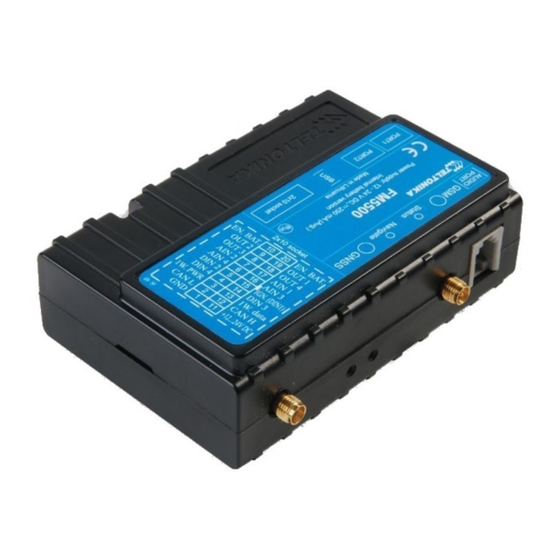
Storage relative humidity 5 … 95 % (non condensating) Mini USB socket Port1 RS232 port channel 1 (RJ45 socket) Port2 RS232 port channel 1 (RJ45 socket) Audio port RJ11 Figure 1 FM5500 view & dimensions in mm (tolerance ±2mm) -
Page 11: Stickers Of Fm5500 Modifications
2.4 Stickers of FM5500 modifications FM5500 has two modifications: GPS/GLONASS and GPS. Figure 2 refers to GPS/GLONASS modification and Figure 3 refers to GPS modification of FM5500. Figure 2 FM5500 sticker for GPS/GLONASS modification Figure 3 FM5500 sticker for only GPS modification... -
Page 12: Technical Information About Internal Battery
In sleep mode a new FM5500 device, operating time approximately 15 hours In deep sleep mode – 137 hours Operating time for a new FM5500 device, working in normal mode (records are being acquired every 10 sec. and sent in packets of 4 records every 60 sec.), is approximately 2 h 30 min. -
Page 13: Electrical Characteristics
2.7 Electrical characteristics Table 2 Electrical characteristics VALUE Min. Typ. Max. Unit CHARACTERISTIC DESCRIPTION SUPPLY VOLTAGE Supply Voltage (Recommended Operating Conditions) 11.8 Supply Voltage (for internal rechargeable battery charging proper functioning) POWER SUPPLY CURRENT (HARDWARE VERSION WITH INTERNAL BATTERY) Deep Sleep, average, Icc.ds Sleep, average, Icc.ds, Vcc=12V Sleep, average, Icc.ds, Vcc=24V Ucc=12.6V, all modules fully working, internal battery is... - Page 14 Common mode input voltage When connecting a COM port to an active external device keep in mind that the first power supply must be connected to FM5500, and then the external device should be powered. Connecting external devices when FM5500 is powered off is not recommended.
-
Page 15: Absolute Maximum Ratings
Analog Input Voltage (Absolute Maximum Ratings) Voltage on Supply Voltage 1-Wire (Absolute Maximum Ratings) Voltage on Data Input/Output 1-Wire (Absolute Maximum Ratings) Voltage on CANH, CANL (Absolute Maximum Ratings) 3 CONNECTION AND PINOUT 3.1 SIM cards insert scheme Gently open FM5500 case using screwdrivers... - Page 16 Take off FM5500 case and insert SIM cards as shown. SIM SLOT 1 (default, recommended for 1 SIM mode) is closer to Assemble device as shown and put screws PCB, SIM SLOT 2 is the upper one into the holes ...
-
Page 17: Installing Fm5500 Drivers
Installing drivers Extract and run VCPDriver_V1.3.1_Setup.exe. This driver is used to detect FM5500 device connected to the computer. Click 'Next' in driver installation window (figures below): Figure 4 Driver installation window This will launch the device driver installation wizard. In the following window click ‘Next’... -
Page 18: Navigate Led
Figure 6 Driver installation window You have now installed drivers for FM5500 device successfully. 3.3 Navigate LED Table 4 Navigate LED operation Behaviour Meaning Permanently switched on GPS signal is not received Blinking every second Normal mode, GPS is working GPS is turned off because: ... -
Page 19: Socket 210 Pinout
OUT 2 Digital output. Channel 2. Open collector output 1. For FM5500 with internal battery this pin is connected with pin 20 (Ext. Battery (+)). When pin 10 and pin 20 are connected, the internal accumulator is on, while disconnected – the internal Ext. -
Page 20: Usb
_____________________________ * FM5500 with external battery is available as separate device. Do not try connecting any external batteries on a standard FM55 device. Contact your sales manager for more details on the solution available. - Page 21 1 – Wire devices One of the FM5500 features is realized 1-Wire data protocol, which enables connection of up to three thermometers (DS1820, DS18S20 and DS18B20) and I-Button DS1990A. Figures 9 and 10 show FM5500 and 1-wire devices connection schemes.
- Page 22 A fuel tank level sensor exists in most of the cars, which shows the approximate fuel level in the driver’s indicator panel. It is possible to connect FM5500 Analog input (if sensor returns analogue signal proportional to fuel level). Figure describes the connection scheme to the FM5500 and fuel tank sensor.
- Page 23 In cases when sensor output signal is negative an additional relay has to be installed to convert negative signal to positive. Figure 13 Inverting relay connection Immobilizer relay When connected a shown below, FM5500 disables engine starter when output is ON. More details about relays can be found below. Figure 14 Immobilizer relay connection Relays...
-
Page 24: Firmware
FM5500 functionality is always improving, new firmware versions are developed. Current module firmware version can be retrieved from Configurator. Connect FM5500 to PC with the USB cable. Launch “Firmware Updater”, select COM port to which device is connected, click connect, and when IMEI and Firmware version fields are filled, start the update. - Page 25 Figure 16 FM5500 firmware updater screen...
-
Page 26: Operational Basics
Figure 17 Firmware updating processes When you see a green table like in Figure 17, it means that the firmware is flashed to FM5500 successfully. You may now close the update window and start using your FM5500 device. 5 OPERATIONAL BASICS 5.1 Operational principles... -
Page 27: Operational Modes
FM5500 perform while in this mode can be found in chapter 11. 5.3 Accelerometer FM5500 has a built in 3 axis accelerometer which allows the device to indicate if vehicle is moving or not, as well as measure acceleration. Accelerometer sensitivity can be configured – it has 2 configurable global parameters: start and stop timeouts that define time intervals in seconds. -
Page 28: Voice Functionality
When the call is triggered, FM5500 dials the number which is defined in “Call Number” field. To initiate a call to FM5500 dial a number of the SIM card that is inserted in FM5500. When FM5500 has an incoming call it can play a selected tone from the “Ringtone” list. -
Page 29: Features
Profile switching functionalities in DUAL SIM operational mode can be found in chapter 7 (DUAL SIM functionality). 5.7 Features Using available features can greatly increase FM5500 usability options. Scenarios Four scenarios are available on FM53 device: a. Digital Output No.1 is used by scenarios - Eco Driving and/or Over Speeding;... -
Page 30: Ibutton List
Next time before driving user has to disable Auto Geofencing with iButton or by turning on car ignition. In case of theft, the car leaves Auto Geofencing zone without authorization and FM5500 device automatically sends high priority record to AVL application. -
Page 31: Configurator Structure
FM5500 has four user editable profiles, which can be both loaded and saved to the device. User can also revert to default settings, by pressing Load Defaults button. After any modification of configuration settings it has to be saved to FM5500 device, otherwise it will not be written to device flash memory. -
Page 32: Information Area
Switch Security Off Information area FM5500 information area is divided into 2 parts located on the top right and bottom of the configurator. When configurator is connected to the device via USB or COM1 port all necessary information about the device is shown here: ... -
Page 33: Parameters Configuration
Figure 22 FM5500 Configurator profiles loading window After changing profile and global parameters, changes can be saved to FM5500 Flash. By pressing “Save” button all 4 profiles and Global parameters are saved to the Flash (Figure 23). Figure 23 FM5500 Configurator profiles saving information 6.3 Parameters Configuration... - Page 34 Voice settings Allows to setup microphone sensitivity and speaker loudness level. Allows entering one number to which FM5500 will be able to call to. Call trigger defines input, which will be used to receive or make a call. Call Settings Usually to that input a button is connected (“Digital Input 1”...
-
Page 35: Settings And Configurable Parameters Menu
Allows configuring COM2 baud rate, parity mode, end line, binary COM2 Settings timeout and 3 prefixes. When two or three temperature sensors are connected to FM5500 it is necessary to define sensor ID to certain property separately. This way Temperature FM5500 will know which temperature sensor is which property. -
Page 36: Gsm Settings
6.3.1.2 GSM Settings 6.3.1.2.1 GPRS ‘GPRS’ defines main parameters for FM5500: destination server Domain (can be entered either IP or domain name) and port. Also both TCP and UDP protocols are supported. Figure 26 GSM->GPRS Settings Configuration APN settings are set in Global parameters screen, if SIM 1 Operator mode is used, than user should insert the same APN settings form both SIM 1 and SIM 2 and insert SIM card into either SIM 1 slot or SIM 2 slot. -
Page 37: Sms
Essential fields in ‘SMS’ part is ‘Login’ and ‘Password’ (Figure 27). This login and password is used with every SMS sent to FM5500. If login and password are not set, every SMS sent to FM5500 device has to include two spaces before command (<space><space><command>). -
Page 38: Operator List
Time tab. 24-Coordinates SMS decoding is described in “FM5500 Protocols” document. 6.3.1.2.4 Operator List FM5500 is able to use GPRS with all operators but if at least one operator is entered in the list, FM5500 is allowed to connect to GPRS only while operating in listed operator’s network. Also operator list has influence on profile switching (see details in chapter 7.1 and chapter 8) if Global... -
Page 39: Features
6.3.1.3 Features 6.3.1.3.1 Mode FM5500 is able to collect records using three methods at the same time: time, distance and angle based data acquisition (chapter 9). Send and Save Parameters configuration is available in Features->Mode category (Figure 30): Min Period – time period change that initializes record save (chapter 9.1). -
Page 40: Scenarios
6.3.1.3.2 Scenarios In Scenarios window four different scenarios are available, two per each Digital Output (DOUT). Only one per digital output can be active at a same time, e.g. DOUT1 can have either ECO driving or Over Speeding enabled, DOUT2 can have either Authorized Driving or Immobilizer enabled. -
Page 41: Geofencing
Trip period. 6.3.1.3.4 Geofencing 6.3.1.3.4.1 Geofencing settings FM5500 has 20 configurable Geofence zones and it can generate event when defined Geofence zone border has been crossed. Figure 33 FM55 Features->Geofencing Configuration (1) -
Page 42: Autogeofencing Settings
Configuration of the parameters is available in Features->Geofencing (Figure 33) Frame border – frame border is an additional border around Geofence zone. It is additional area around defined zone used to prevent false event recording when object stops on the border of the area and because of GPS errors some records are made inside area and some –... -
Page 43: Ibutton List
Figure 35 FM55 Features->Geofencing Configuration (2) Auto Geofencing option can be configured by following parameters (Figure 35): Activate – Enable or Disable Autogeofence functionality Activation TMO – Time period before Geofence is activated after vehicle stops. Deactivate By: ... -
Page 44: I/O
If all I/O elements are disabled AVL packet comes with GPS information only. After enabling I/O element(s) AVL packet in couple with GPS information contains current value(s) of enabled I/O element. 6.3.1.4.1 FM5500 available I/O list Table 9 PERMANENT I/O elements list description Permanent I/O elements... - Page 45 Permanent I/O elements (are always sent (with every record) to server if enabled) Property Name Bytes Description Dallas Temperature 1 10 * Degrees ( °C ), -55 - +115, if 3000 – Dallas error Dallas Temperature 2 10 * Degrees ( °C ), -55 - +115, if 3000 – Dallas error Dallas Temperature 3 10 * Degrees ( °C ), -55 - +115, if 3000 –...
-
Page 46: I/O Configuring
Eventual IO elements (generated and sent record to server only if appropriate conditions are met) Property Name Bytes Description Geofence zone 11 Event: 0 – target left zone, 1 – target entered zone Geofence zone 12 Event: 0 – target left zone, 1 – target entered zone Geofence zone 13 Event: 0 –... - Page 47 Then it switches its operating profile to Profile 4 (for details see chapter 8.1). SW2X priorities switch profiles on event (SW21 – Profile 1, SW22 – Profile 2 and so on). High Level - define I/O value range. If I/O value enters or exits this range, FM5500 generates event.
-
Page 48: I/O Properties
Pos. DESCRIPTION Where: Mean – Value calculated during actual cycle Mean-1 – Value calculated during previous cycle; CONST – Averaging constant; REALVAL – Real value detected on digital input. 6.3.1.4.3 I/O properties I/O properties are additional data sources, which are recorded along with usual GPS data. I/O#0 property parameter (ID=300) Parameter defines I/O property value. - Page 49 Minimum Maximum Recommended Goes with (depends on) Value value value value parameters type I/O#0 priority (ID=301) I/O#0 Low level (ID=303) 9999999 I/O#0 logic operand (ID=304) I/O#0 averaging constant (ID=305) I/O#0 Low level (ID=303) Parameter defines low value of triggered I/O property. This parameter is used to set thresholds for I/O properties to generate events.
-
Page 50: Can
Other I/O property elements can be configured in the same logic. All I/O element parameters are listed below. Table 19 I/O Elements I/O element I/O element I/O Element Number I/O Element Number parameters parameters I/O#0 – Digital input 1 300 – 305 I/O#17 –... - Page 51 Parameter defines CAN element ID length. CAN element ID could be 11 or 29 bits length. For 11 bits ID parameter value is 0, for 29 bits ID – 1. Table 21 CAN Type ID Minimum Maximum Recommended Goes with (depends on) Value value value...
-
Page 52: Configurable Parameter Values And Global Parameter Values
CAN#8 850 – 852 CAN#9 860 – 862 CAN#10 870 – 872 Table 24 CAN elements and parameters There are only 14 I/O parameters that could use Averaging Constant: Digital Inputs (1-4); Analog Inputs (1-4); Battery Voltage; Battery Current; External Voltage; PDOP; HDOP; Speedometer. I/O parameters: “Current Profile”, “Fuel level meter”... - Page 53 Frame Border (in 9999999 1000 meters) Zone #1 Shape 0 (Circle) 1 (Rectangle) Zone #1 Priority (0 – Low, 1 – High, 2 – Panic, 4, 5, 6, 7 – 7 (exl. 3) SW21, SW22, SW23, SW24) Zone #1 Generate Event (0 –...
- Page 54 Force Max Braking Force 0.5 (5) 10.0 (100) Float Max Cornering 0.5 (5) 10.0 (100) Float Force Acceleration 0.25 (6) 1.25 (32) Detection Sensitivity Breaking Detection 0.25 (6) 1.25 (32) Sensitivity Cornering Detection 0.25 (6) 1.25 (32) Sensitivity Acceleration Active Output Duration Breaking Active Output Duration...
-
Page 55: Global Parameters
SMS Password Empty 5 char Empty S8[5] Authorized phone 260- Empty 16 char Empty S8[17] numbers Operator Code 99999999 SMS Data send Binary Binary 20 byte array week time schedule decoding decoding 6.3.1.6.2 Global parameters Table 26 Global parameters values Parameter Possible Parameter Value Default Value... -
Page 56: Read Records
SIM2 GPRS PASS all char range Read Records FM5500 supports two records sizes mode: 64 Bytes and 256 Bytes. In 64 Bytes Mode there can be less IO elements activated. Combined with 16 MB flash these characteristics are maintained: Record Size Flash Size + Max records Time needed to fill memory... - Page 57 (please see Figure 33 below). Figure 39 RecSize settings, 256 Byte Length Records mode When the 256 Byte length Records mode is chosen FM5500 can save up to 47.000 records. Record size is 256 bytes. When 64 Byte Length Records mode is chosen (please see Figure 34 below) all existing records will be deleted.
- Page 58 Before deleting the records, the Warning window will show up to inform that after pressing „Yes“ button, all the records will be deleted from memory and all IO Elements will be disabled (please see Figure 41 below): Figure 41 Warning window when changing RecSize Settings When switching from 64 Byte Length Records mode to 256 Byte Length Records mode, the IO elements are not disabled, but the memory is fully formatted and all the records in memory will be lost.
-
Page 59: Profile Switching In 1 Sim Operation Mode
4 profiles. This means that if you set FM5500 to call to a predefined number, you will be able to call it while using any profile. Basic scheme of Global parameters and profiles is shown below. According to the scheme, every profile has a list of parameters. - Page 60 If there are no operator codes entered in all profiles after operator search task FM5500 will check all 3 profiles and won’t find any operators in any list. In such a case, FM5500 will switch to profile 3. Note that before switching to profile 3, the device closes the GPRS session.
-
Page 61: Profile Switching Dependence On I/Oevent
SW21, SW22, SW23, SW24 stands for “Switch to profile No. X”. After an event happens, FM5500 switches to a defined profile. Using profile switching you can create smart applications. SW2X actions can be performed only if “Profile change on event” is enabled in... -
Page 62: Example #1
2) H:1 L:1 Event: on entrance 3) H:1 L:1 Event:on exit Profile Y 1) H:0 L:0 Event: on exit 4) H:0 L:0 Event: on entrance Profile X Figure 45 Digital input event criteria Example #1 Configuration of Profile1 to switch to Profile2 on DIN1 value change from 0 to 1: Figure 46 Switch to profile on event (1) Example #2 Configuration of Profile2 to switch to Profile1 on DIN1 value change from 1 to 0:... -
Page 63: Dual Sim Functionality
SIM1 slot for FM5500 to switch minimum times. If SIM card is inserted into SIM 2 slot and 1 SIM operator list mode is used, FM5500 will work normally, but there will be more switching activities. In addition, APN settings in Global parameters should be entered for SIM 1 and SIM 2 to avoid not sending records over GPRS. -
Page 64: Home Network
Home operator using the SIM card, which was inserted for and works according to the Home profile parameter settings. If none of the Home operators could be connected with, FM5500 switches to the SIM 1 card tries to connected to its roaming operators from SIM 1 Roaming profile. -
Page 65: Sim 1 Roaming
Roaming operators list. If there are no available operators from Home operator list and SIM 1 Roaming operators list, FM5500 scans for available operator in the SIM 2 Roaming operator list. If there is an available SIM 2 Roaming operator in the list, FM5500 switches the profile to SIM 2... -
Page 66: Unknown Operator
The FM5500 switches to Unknown operator profile using the SIM card it has used before (FM5500 doesn’t switch the SIM cards) when SIM 1 and SIM 2 operator lists are empty and there is no possibility to connect to SIM 1 and SIM 2 Home operators. In this profile FM5500 connects to an operator from the list, received from the network, with the best signal quality. - Page 67 Figure 53 Unknown Operator List...
-
Page 68: Dual Sim Algorithm
Dual SIM algorithm Two SIM cards use algorithm is shown in the diagram (Figure 54). Figure 54 Dual SIM connection algorithm... - Page 69 The FM5500 is always trying to connect to Home operator. If it cannot connect, then it goes to Roaming Operator. The Roaming Operator is chosen by priority. Higher placed operator in the operators list has higher priority. If impossible to connect to Roaming Operator from operator’s list or the operators list is empty, then the FM5500 connects to Unknown operator.
-
Page 70: Data Acquisition
9 DATA ACQUISITION Data can be acquired using GPS or I/O elements. GPS data is for basic vehicle tracking, data acquisition by I/O elements gives more specific information. 9.1 GPS data acquisition There are three ways of GPS data acquisition which are configured in Features > sMode menu (Figure 55). -
Page 71: Min. Distance
Min. Distance Distance based data acquisition (Figure 57) – records are being acquired when the distance between previous coordinate and current position is greater than defined parameter value. Entering zero means that data won’t be recorded. This method is suitable for non-urban territories where moving trajectory is straight. -
Page 72: Event Generation
Event generation There are five record event generation types (I/O speed is taken as I/O value example), please refer to Figures below. 1. On Zone Exit 2. On Zone Entrance Speed, Speed, Km/h Km/h High Level High Level Low Level Low Level - Event Generated / Record Saved Time, t... -
Page 73: Sleep Mode
send data to server; 11 DEEP SLEEP MODE While in deep sleep mode, FM5500 sets GPS receiver to sleep mode and turns off GSM/GPRS module (it is not possible to wake up device via SMS), therefore records with last good coordinates are being saved and sent to AVL server if configured (GSM/GPRS module is turned on only to send data and after that is turned off). -
Page 74: Features And Scenarios
can save periodical or eventual records; send data to server; Note: If there is no need to save or send periodical data, FM5500 has to be configured to switch to another profile on Deep Sleep Event where Min Period and Send Period parameters are 0 or big enough. -
Page 75: Mounting Requirements
(Figure 64) mounting recommendations are displayed. Please note that beside those recommendations 1. You can choose how FM5500 is deployed. It means that that there is no effect to measurements if FM5500 top/bottom side points up or down. 2. Device can be deployed at any place in the car. - Page 76 Deviations of maximum +/- 15 are allowed (Figure 65). Figure 65 MAX deviation from horizontal plane of FM5500 mounting Figure 66 Horizontal position MAX deviation of FM5500 mounting Horizontal position must be as flat as possible – parallel with vehicle plain.
-
Page 77: Configuration
Configuration Parameters used with Eco/Green driving functionality. Figure 67 ECO/Green driving configuration parameters Table 27 ECO/Green Driving parameters description ECO/Green driving configuration Description parameter name Eco/Green Driving Disable/ Enable Eco Driving/ Enable Green driving functionality Value which can be reached while accelerating without triggering harsh Max Acceleration Force acceleration event. -
Page 78: Data Output
If any of three cases are satisfied event is generated. Record is saved and sent to server (FM5500 must be configured properly). Event value is multiplied by 10 before sending/saving record to get more precision when displaying data*. -
Page 79: Immobilizer Scenario
Figure 70 Authorized driving configuration parameters Authorized Driving. Enable/Disable Authrized Driving. Edit iButtons List. Enter authorized iButtons 12.5 COM1 and COM2 Working Modes Silent Mode FM5500 doesn't do any activity in silent mode. Logs aren’t saved and any data isn’t sent. -
Page 80: Fm Log Mode
FM Log Mode This is default mode of the FM5500. It is suitable for debugging. LLS Mode 12.5.1.1 LLS Mode Configuration 1. External Devices->COM1 Settings->Baudrate = 19200 2. External Devices ->COM1 Settings->Mode = LLS 3. External Devices ->COM2 Settings->Baudrate = 19200 4. -
Page 81: Multipacket Support
Multipacket support With multipacket support FM5500 can put two or more smaller input strings in one bigger special packet . This reduces possibility to miss packets from uart. Example: Input String: Hello$0aHello$0aHello$0a Without Multipacket server will see: Hello$0a With Multipacket server will see: Hello$0aHello$0aHello$0a LCD Mode Configuration 1. -
Page 82: Rfid Mf7 Mode Configuration
RFID MF7 Mode Configuration 1. External Devices ->COM1 Settings->Baudrate = 9600 2. External Devices ->COM1 Settings->Mode = RFID MF7 1. External Devices ->COM2 Settings->Baudrate = 9600 2. External Devices ->COM2 Settings->Mode = RFID MF7 3. External Devices ->COM2 Settings->Parity = None Garmin Mode Configuration 12.5.1.3 Settings 1. -
Page 83: Firmware Configuration
12.5.1.4 Firmware Configuration Supported Garmin protocols: A*** (http://developer.garmin.com/lbs/fleet-management/fmi-protocol-support-matrix/) Blocked Garmin ID’s: Command 0A Date/Time Data 0E Unit ID/ESN 26 Pvt Data 33 Legacy Stop Message 87 Legacy Text Message 88 Ping 0260 Ping response 0261 ... -
Page 84: Tcp Link Mode (Binary)
TCP Link Mode (Binary) This mode is the same as above but binary message will be accepted to/from COM port. This mode also have some advanced filtering capabilities. 1. External Devices ->COM2 Settings->Baudrate = any of available baudrates 2. External Devices ->COM2 Settings->Mode = TCP Link Mode 3. -
Page 85: Sms Command List
13 SMS COMMAND LIST SMS commands are used to identify FM5500 current state, possible configuration errors, perform reset, set parameters, switch on/off outputs, etc. SMS commands should be sent along with module login and password and sender number must be entered in the authorized number list (if at least one other number is entered). Please see SMS settings in chapter 6.3.1.2.2 for more details. -
Page 86: Getstatus
setparam # # Set parameter value according entered ID and Value. 1.# - ID value. 2.# - New Parameter Value flush Initiates all data sending to specified target server #,#,#,#,#,#,# 1.# - IMEI 2.# - APN 3.# - LOGIN 4.# - PASS 5.# - IP 6.# - PORT 7.# - MODE (0-TCP/1-UDP) -
Page 87: Getweektime
13.2 getweektime Table 30 getweektime Response details Description Clock Sync Indicates system clock synchronization status. 0 – System is not synchronized, 1 – System synchronized Day Of Week – indicates current day of week starting from 1 – Monday, 2 – Tuesday, etc. -
Page 88: Getcfgtime
Actual Speed Latitude (Last good Latitude), Longitude (Last good Longitude) Google Maps Link Example: D:2013/7/4 T:0:0:0 S:0 C:0, 0 Url: http://maps.google.com/?q=0,0&om=1speed:0 13.7 getcfgtime Table 35 getcfgtime Response details Description Date/Time Returns last performed configuration date and time. Answer Example: Last Configuration was performed on: 2010.4.15 5:45:19 13.8 getgps Table 36 getgps Response details... -
Page 89: Getver
13.12 getver Table 37 getver Response details Description Code Ver Firmware version Device IMEI IMEI Device ID Device ID is used to detect which type of configuration to load Modem App Ver Version of modem application Answer Example: Code Ver:0.48.17 Device IMEI:353976010139156 Device ID:000001 Modem APP Ver:2007.11.07 13.13 getio... -
Page 90: Deleterecords
Answer Example: INI:2007/8/24 10:15 RTC:2007/8/24 12:43 RST:2 ERR:11 SR:182 BR:0 CF:0 FG:0 FL:0 UT:0 P:1 P0:0 P1:1 P2:0 P3:0 P4:0 SMS:2 NOGPS:0:0 GPS:3 SAT:7 RS:7 13.15 deleterecords Deletes all saved records from device memory. Device does not send a response back to the sender. -
Page 91: Flush
13.20 flush #,#,#,#,#,#,# Initiates all data sending by GPRS to specified target server. Comma separated parameters go as numbered: 1.# - IMEI 2.# - APN 3.# - GPRS LOGIN 4.# - GPRS PASSWORD 5.# - IP 6.# - PORT 7.# - MODE (0-TCP/1-UDP) Parameters are separated by comma (no spaces needed). -
Page 92: Banlist
This SMS command is used to switch the SIM slot forcibly. After this command is sent to FM5500 the SIM disconnects from operator and switches to another SIM card, then it connects to another SIM card’s operators by priority. If after switching FM5500 connects to an unavailable operator after 10 minutes it will connect to an optimal operator. -
Page 93: Getsiminfo
13.27 getsiminfo Returns the active SIM info, FM5500 is using at the moment. Answer Example: SL:0,S1F:0,S1S:0,S1I:246021005041494,S1H:24602,S1R:0,S2F:0,S2S:0,S2I:,S2H:0,S2R:0 Table 46 getsiminfo Response details Description SIM Slot [0,1] SIM1 Forced Switch SIM1 Status SIM1 IMSI SIM1 HOME Operator SIM1 Roaming Operator SIM2 Forced Switch... -
Page 94: Setlvcanprog
13.29 setlvcanprog # Set LV-CAN program number via SMS: SMS Text: “setlvcanprog 139” Response: “CAN program Nr:139” 13.30 getlvcaninfo Get LV-CAN info by SMS Full LV-CAN information via SMS: SMS Text: “ getlvcaninfo” Response: “ Prog: 139 SWRevison: 6 KernVer: 10 KernVar: 49 MdlID: 8884443332221110”... -
Page 95: General Description
• Status of brake pedal * • Engine Torque * • Actual fuel • Accelerator pedal position * • Status engine brake • Speed * • RPM • Engine hours • Vehicle Weight * • Fuel level • Tachograph data * 14.1 General description ... -
Page 96: Example
* Availability of parameter depends on vehicle’s model and configuration of FMS interface of the truck. Figure 73 CAN baud rate configuration window Note that If FM5500 is set to “Autobaud” mode it will always check for CAN network even if device isn’t connected to any of it. - Page 97 All Mercedes Benz Actros 2 models with Vehicle Identification Number (VIN) starting with WDB93 have a possibility to connect FM5500 module to CAN bus. This can be done by connecting to special PSM module (which may or may not be included in the truck) or ground module of the vehicle.
- Page 98 (Figure 78 and Figure 79). Figure 78 Fuel consumption message indication When certain message is filtered, FM5500 checks which data bytes should be sent to server. Document indicates that 5-8 bytes are used in FMS standard. Table 46 FMS standard – fuel consumption (5-8 bytes)
-
Page 99: Autocan Description
AutoCAN function allows user to automatically scan for available messages on CAN bus and configure CAN data sending to server. In order to configure AutoCAN connect FM5500 to computer with Port ½ cable. Launch FM55xx configurator. Push “Connect“ button, then „CAN“... -
Page 100: Configuration
Figure 80 Entering CAN configuration SCAN scans once for available messages on CAN bus; Monitoring – toggles scanning of messages on CAN bus every 3 seconds; Offline Configuration – enables CAN configuration when FM53xx is not connected to CAN bus;... -
Page 101: Can Monitoring
o Hysteresis – record is generated when increasing parameter value becomes higher than High value, and decreasing becomes less than Low value o Event on exit – record is generated when parameter value becomes higher than High value or lower than Low value; o Event on entrance –... -
Page 102: Offline Configuration
Configuration section. Offline configuration When FM5500 device is not connected to CAN bus you can configure CAN data sending by pushing “Offline configuration” button. When offline configuration is enabled a configuration table of all FMS standard CAN data is shown. -
Page 103: Autocan Id List
AutoCAN ID list Table 48 AutoCAN ID list Category Par Nr in Par Nr. In (signal) name Size Param IO Value range name P:FMS: P:FMSDAT: (Bytes) Brake switch 0 = pedal released 1 = pedal depressed wheel based speed 0-65536 (km/h)* cruise control active 0 = switched off 65265 –... - Page 104 65217 – High High resolution total 0 – 21055406 km* Resolution vehicle distance X Vehicle Distance 65216 – Service Service distance -160 635 – 167040 Information Vehicle motion X 0 – Motion Not Detected 1 – Motion Detected driver 2 working state 0 –...
- Page 105 65269 – Ambient Air [-273 – 1770]oC – Ambient Temperature X Ambient Air Conditions Temperature* 65131 – Driver’s Driver 1 129,130,131 24 ASCII Bytes per Identification Identification Driver ID 65131 – Driver’s Driver 2 Identification 132,133,134 24 ASCII Bytes per Identification Driver ID Fuel rate X...
- Page 106 Cruise control is switched on. It is not ensured that the engine is controlled by cruise control, as in the case of a large driver’s demand the engine is controlled by the driver while cruise control is active(maximum selection of cruise control and driver’s demand). The cruise control is set to 0 if a switch off condition occurs.
- Page 107 01000 Accelerate 01001 Accelerator Override 01010 Preprogrammed set speed 1 01011 Preprogrammed set speed 2 01100 Preprogrammed set speed 3 01101 Preprogrammed set speed 4 01110 Preprogrammed set speed 5 01111 Preprogrammed set speed 6 10000 Preprogrammed set speed 7 10001 Preprogrammed set speed 8 10010 PTO set speed memory 1 10011 PTO set speed memory 2...
- Page 108 Preprogrammed PTO Governor Set Speed 4 01101b —used to indicate that the remote PTO device is establishing a fourth preprogrammed PTO governor set speed (user programmable) as the current operating speed. Preprogrammed PTO Governor Set Speed 5 01110b —used to indicate that the remote PTO device is establishing a fifth preprogrammed PTO governor set speed (user programmable) as the current operating speed.
- Page 109 Engine percent load at current speed: The ratio of actual engine percent torque (indicated) to maximum indicated torque available at the current engine speed, clipped to zero torque during engine braking. Data Length: 1 byte Resolution: 1 %/bit, 0 offset Data Range: 0 to 250 % Operational Range: 0 to 125% Type: Status Supporting information:...
- Page 110 Supporting information: PGN 61444 Note: Value sent to server is already adjusted with bitgain. Since data as sent as U32, value after floating point is ignored. Axle weight: Total mass imposed by the tires on the road surface at the specified axle. Data Length: 2 bytes Resolution: 0.5 kg/bit, 0 offset Data Range: 0 to 32,127.5 kg Operational Range: same as data range...
- Page 111 Information to be ASCII equivalent of the numeric revision level of the FMS document, 00.01 to 99.99. The first released version will be 01.00. Note: Byte 2 and byte 3 represents the SW version supported for trucks. Version number in the format ab.cd where Byte 2 represents “a”...
- Page 112 00 On request mode is not supported 01 On request mode is supported 10 Reserved 11 Don’t care Data Length: 2 bits Resolution: 4 states/2 bit, 0 offset Data Range: 0 to 3 Operational Range: same as data range Type: Status Supporting information: PGN 64977 Note: Firmware captures all values [0x00-0x03].
- Page 113 Supporting information: PGN 65132 Note: Firmware captures all values [0x00-0x03]. Driver 1/2 working state: State of work of the driver. 000 Rest – sleeping 001 Driver available – short break 010 Work – loading, unloading, working in an office 011 Drive – behind wheel 100-101 Reserved 110 Error 111 Not available...
- Page 114 0111-1100 Reserved 1101 Other 1110 Error 1111 Not available Data Length: 4 bits Resolution: 16 states/4 bit, 0 offset Data Range: 0 to 15 Operational Range: same as data range Type: Measured Supporting information: PGN 65132 Note: Firmware captures all values [0x00-0x0F]. Driver card, driver 1/2: Indicates the presence of a driver card 00 –...
- Page 115 00 – Normal performance 01 – Performance analysis 10 – Error 11 – Not available Data Length: 2 bits Resolution: 4 states/2 bit, 0 offset Data Range: 0 to 3 Operational Range: same as data range Type: Status Supporting information: PGN 65132 Note: Firmware captures all values [0x00-0x03].
- Page 116 Resolution: 1/256 km/h per bit, 0 offset Data Range: 0 to 250.996 km/h Operational Range: same as data range Type: Measured Supporting information: PGN 65132 Note: Since FM FW sends this parameter as U16 (2 Bytes), value after floating point is discarded. So data limit becomes [0-250].
- Page 117 Data Length: 2 bytes Resolution: 0.05 L/h per bit, 0 offset Data Range: 0 to 3,212.75 L/h Operational Range: same as data range Type: Measured Supporting information: PGN 65266 Note: Since FW sends this parameter as U32, value after floating point is discarded. Data limit becomes [0-3,212].
-
Page 118: Autocan Configuration Over Sms
14.5 AutoCAN Configuration over SMS SMS command format: “<login><space><password><space>setparam<space><Parameter ID><space><value>” if there is no login and password configured in FM configuration, 2 spaces must be used before command : <space><space><command>. Parameter ID explanation: 20090 digit represents Profile number. digit is not used. and 4 digits represents AutoCAN element ID. -
Page 119: Autocan Element Parameters
Driver 2 time rel. states Driver 1 card X Driver 2 card X Direction indicator Tachograph performance X Handling information X System event X Tachograph vehicle speed X 65262 – Engine Temperature 1 engine coolant temperature X 65269 – Ambient Conditions Ambient Air Temperature X 65131 –... -
Page 120: Parameter Value Reading
LV-CAN200 must be set to program number which depends on vehicle model. Needed program number is always written on LV-CAN200 mounting scheme. Please contact Your Teltonika sales manager to get latest supported vehicle list and mounting scheme for your vehicle, please provide CAR manufacturer, model and year information. -
Page 121: Lv-Can200 Program Number Configuration Via Sms Command
LV-CAN200 program number configuration via SMS command LV-CAN200 program number can be set remotely, using SMS command: setlvcanprog X X is new program number value. Selecting LV-CAN200 program number manually Steps to set program number: Hold SWITCH down till LED stars blinking ... -
Page 122: Connecting Fm5500 With Light Vehicles Can Adapter
15.3 Connecting FM5500 with Light Vehicles Can adapter Connect USB Plug to FM5500 device, connect Light Vehicles Can adapter to other end of the cable. Connect Light Vehicles Can adapter Pin 1 and Pin 2 to cars CAN bus. CAN interface location of the supported light vehicle is described on mounting scheme. -
Page 123: Fm5500 Configuration
FM5500 can be configured using “SCAN” function or “Offline Configuration” (Figure 89) SCAN function – is in use when FM5500 is connected to CAN adapter (Figure 87), then wait 10s (Note, that car engine must be started), disconnect adapter from FM5500, and connect PC USB cable to FM5500 Device (Figure 88). - Page 124 CAN bus data event capturing Monitoring method is used when user wants to receive CAN data on regular basis, for example every 20 seconds. Event functionality is used to store additional AVL packet when state of CAN element is changing.
-
Page 125: Parameters Id
15.5 Parameters ID When no I/O element is enabled, AVL packet comes with GPS information only. After enabling I/O element(s) AVL packet along with GPS information contains current value(s) of enabled I/O element. AVL packet decoding is described in “FMXXXX Protocols” document. List of available CAN bus data, parameter size, ID and value range you can find in table 9.1. -
Page 126: Sms Configuration
15.6 SMS Configuration All LV-CAN200 IO elements can be configured remotely via SMS command. First ID number is Progifile number( 5 – profile 1, 6 – profile 2, 7 - Profile 3, 8 – profile 4), seconds ID number is always ‘0’. -
Page 127: Can Program Number Request By Sms
15.7 CAN Program Number request by SMS CAN program number can be obtained via SMS: SMS Text: “ getlvcanprog ” Response: “CAN Program Nr: XXX” 15.8 Get LV-CAN info by SMS Full LV-CAN information via SMS: SMS Text: “ getlvcaninfo” Response: “Prog: 139 SWRevison: 6... -
Page 128: Rs485 Receive (Silent) Mode
Figure 90 RS485 Settings window The modes are described below are setting in the configuration window. RS485 Receive (Silent) Mode Figure 91 Silent Mode RS485 Works in receive mode. Support debug and testing commands. When command is received answer is sent after that it back up to Receive mode. -
Page 129: Rs485 Receive (Tcp Link) Mode
RS485 Receive (TCP Link) Mode Figure 92 COM TCP Link Mode RS485 works in receive mode. When data received from server RS485 is switched to transmit mode for 2 seconds. RS485 Receive (LLS) Mode Figure 93 LLS Mode The mode supports up to two LLS. Baud rate must be 19200. LLS have receiver id. Smaller ID will get ID: 201 and ID: 202. -
Page 130: Rs485 Transmit (Gps Nmea) Mode
RS485 Transmit (GPS Nmea) Mode Figure 95 NMEA Log Mode RS485 works in transmit mode, it prints NEMA. It won’t respond to commands RS485 Self-Test Mode Figure 96 Self Test Mode Both transmitter and receiver are active. Transmitted info will be echoed back. 16.2 RS485 interface Port connection diagram are shown on the Figure 97: Figure 97 Port 1 connection diagram... -
Page 131: Rfid
Figure 98 RFID I/O parameter To set up FM5500 so it can be connected to an RFID reader, External devices have to be set up. Go to External devices and set up COM1 or COM2 settings to RFID Mode or RFID MF7 Mode (the used mode depends on the mode that the RFID reader works). -
Page 132: Garmin
Figure 99 RFID Global parameter settings The difference between RFID Mode and RFID MF7 Mode is that in RFID Mode FM5500 understands RFID messages that are in hexadecimal format and RFID MF7 Mode understands messages that are in decimal format. For example: RFID Mode message –... -
Page 133: Supported Garmin Fmi Protocols
The following is a list of protocols supported and the corresponding feature/benefit. FM5500 can fully support Fleet Management Interface (FMI) versions up to 2.1. Other or higher versions may be supported, but Teltonika is not responsible for the changes made by Garmin, which may affect the work of FM5500 and Garmin products. -
Page 134: Enhanced Protocols
• Garmin can also provide confirmation that driver has received a particular Stop, read the details, or deleted it from list. • Can provide confirmation that a Stop has been completed. Estimated Time of Arrival Protocol: • Dispatcher/office can request the ETA of the current stop/job in progress. •... -
Page 135: Destination Message
18.6 Connection and pinout Figure 101 RJ45 Pinouts In order to connect Garmin PND to FM5500, Garmin mode has to be set in External devices settings (Figure 102). Simply choose Garmin mode in either COM1 or COM2 settings mode, but you cannot activate Garmin mode in both ports at the same time. -
Page 136: Lls Sensor
5.zip. Software version updates: http://www8.garmin.com/support/download.jsp. For more information about Garmin PND device connectivity to FM5500 and additional information, please contact to your local sales representative. 19 LLS SENSOR LLS sensor series liquid level sensors are solid-state capacitive devices with no moving parts. -
Page 137: Specifications
Port 2 can use only RS-232 protocol. The FM5500-LLS fuel sensor connection schemes are shown below. *Teltonika is not responsible for any changes made by the manufacturer, which is not declared in fuel level sensor documentation. - Page 138 FM5500-LLS two fuel sensors connection via RS232 scheme RJ-45 male plug to Port 1 and one fuel sensor connection via RS232 to Port 1 is shown on Figure 103. Figure 103 FM5500-LLS two fuel sensor connection via RS232 scheme RJ-45 male plug to Port 1...
- Page 139 LLS side (for example with hot shrink tubing), for avoiding any undesirable connections (with power supply positive, with ground, or between themselves). Then FM5500 must be configured. Both fuel level and fuel temperature has to be set up by configurator’s I/O menu (Figure 106):...
- Page 140 Enable ID11 and ID12, or ID13 and ID14, or all four I/O elements (Figure 106) at the same time because two LLS sensors can be connected to FM5500 at the same time (for example if a vehicle has two fuel tanks).
- Page 141 Then, enter these values in Excel and calculate another value N+, according to the formula: FM5500 converts the read data using this formula, so we need to have the converted values also. Next, enter the new values in Excel and create a scatter chart, like in Figure 108.
- Page 142 Figure 108 Scatter chart creation Then right-click on the chart line and select “Add Trendline” (Figure 109). Figure 109 Adding a trendline Select a polynomial type of 5 order trendline. Also select “Display equation on chart” checkbox (Figure 110).
- Page 143 Figure 110 Selecting polynomial order A new line appears alongside the created one, as well as a formula for that new line (Figure 111). Figure 111 Calculated polynomial line and calculation formula Final view of the formula should be:...
- Page 144 Here, the polynomials a0…a5 have to be written in the polynomial calculation on the server. If it is required for FM5500 to send the data in liters, these polynomials can be written in the configuration of the device. To do this, go to global settings, and choose both ports to work in LLS mode (Figure 112).
- Page 145 Figure 113 LLS sensor advanced (polynomial) setup After the configuration is saved successfully FM5500 is ready to send measured fuel level. For additional information about LLS sensors, their configuration and connectivity to FM5500, please contact us to your local sales representative.
-
Page 146: Connecting Up To Five Rs485 Lls Sensors
19.4 Connecting up to five RS485 LLS sensors Several LLS sensor connection on RS485, pinout for A1, reference Figure 114 Figure 114 Sensors connection Five LLS sensors can be connected using 01.03.07 or above. LLS device connection: 1. Configure FM55 Untit. 2. -
Page 147: Fm55 Configuration For Rs485 Lls
FM55 Configuration for RS485 LLS a) 1-5 sensors Manual Oder Selection 1. Under RS485 settings select LLS Mode 2. Ensure Baudrate is 19200 3. To order LLS sensors manually. (attach ID that will be send to server) select Multi settings. Figure 115 RS485 configuration 4. - Page 148 4. Select No Pylynoms Figure 118 COM port2 configuration 5. In Profile1, Profile2, Profile3, Profile4 – enable required IO fields for LLS1 and LLS2 Figure 119 I/O element configuration 6. Lower sensor adress will have ID:201 other ID:203. c) One or two sensors Level Calucualtion using Polynoms Values 1.
- Page 149 Figure 121 COM port2 configuration using polynomials 5. Configure Polynoms, (for calibration) or leave default if no calibration 6. Value will be in liters (depends on calibration) on ID:201 7. In Profile1, Profile2, Profile3, Profile4 – enable required IO fields for LLS1 and LLS2 Figure 122 I/O element configuration Note: ID: 203 will hold raw LLS2 value if enabled.
-
Page 150: Gprs Commands
It is possible to send commands to FM5500 using GPRS. When FM5500 sends records periodically to a server, a message could be sent from the server and FM5500 will reply to it. FM5500 has to be connected to the server in order to receive commands. - Page 151 #SET AUPX=Y,Z,W Set APN, user login and password to the configuration of a certain profile, X – profile, Y – APN, Z –, user login W – password #GET REPRTX Get MinPeriod from the configuration of a certain profile, X – profile #SET REPRTX=Y Set MinPeriod to the configuration of a certain profile, X –...
- Page 152 deleterecords Delete all records saved on FLASH getio Readout digital inputs and outputs, analog inputs readio # Readout input value according entered ID, # - ID value setdigout Set digital outputs XXXX Y1 Y2 Y3 0 – OFF, 1 – ON Y1 –...
-
Page 153: Debug Mode
21 DEBUG MODE FM5500 is able to transmit its current state when connected to PC using PORT1/2 cable. It is used to detect errors and provide information to possible solutions when operating as unexpected. Contact our sales manager to get Terminal. After launching it choose baud rate 115200 and hardware control –... -
Page 154: Change Log
22 CHANGE LOG Versi Date Comments 2012-12-21 Preliminary release draft 2012-12-27 Correction according to Support notes 2012-12-31 Correction according to Support notes 2013-01-03 Correction according to Support notes 2013-01-08 Correction according to Support notes 2013-01-14 Final version 2013-01-31 Minor changes 2013-03-07 Minor changes 2013-07-18... - Page 155 2016-08-22 2.08 Corrected Virtual COM Port driver download link...
Need help?
Do you have a question about the FM5500 and is the answer not in the manual?
Questions and answers