Advertisement
Quick Links
SERVICE MANUAL
Ver 1.1 2006.09
•
Tourist model of DCR-PC7 is different from US model of DCR-
PC7 only in the accessory and packing materials.
•
Tourist model of DCR-PC7E is different from E model of DCR-
PC7E only in the accessory and packing materials.
MICROFILM
DCR-PC7/PC7E
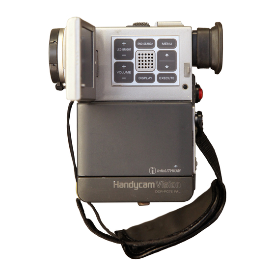
Photo : DCR-PC7
: RMT-808
SPECIFICATIONS
DIGITAL VIDEO CAMERA RECORDER
RMT-806/807
US Model
Canadian Model
AEP Model
UK Model
Tourist Model
DCR-PC7/PC7E
D MECHANISM
For MECHANISM ADJUSTMENTS, refer to the
"DV MECHANICAL ADJUSTMENT MANUAL I"
(9-973-815-11).
— Continued on next page —
DCR-PC7
E Model
DCR-PC7E
Advertisement

Related Manuals for Sony DCR-PC7


Summary of Contents for Sony DCR-PC7
- Page 1 DCR-PC7/PC7E Photo : DCR-PC7 D MECHANISM : RMT-808 • Tourist model of DCR-PC7 is different from US model of DCR- For MECHANISM ADJUSTMENTS, refer to the PC7 only in the accessory and packing materials. “DV MECHANICAL ADJUSTMENT MANUAL I” •...
- Page 2 THESE COMPONENTS WITH SONY PARTS WHOSE PART FONCTIONNEMENT. NE REMPLACER CES COMPOSANTS NUMBERS APPEAR AS SHOWN IN THIS MANUAL OR IN SUP- QUE PAR DES PIÈCES SONY DONT LES NUMÉROS SONT PLEMENTS PUBLISHED BY SONY. DONNÉS DANS CE MANUEL OU DANS LES SUPPLÉMENTS PUBLIÉS PAR SONY.
- Page 3 SERVICE NOTE 1 Ejecting with the cabinet (L) assembly removed • Refer to “2. DISASSEMBLY”, and supply power with the cabinet (L) assembly removed (however leave the flexible board connecting the cabinet (L) assembly and main unit connected). CC DOWN SW •...
- Page 4 DCR-PC7/PC7P SECTION 2 DISASSEMBLY 2-1. REMOVAL OF CABINET (L) ASSEMBLY 9 Screw (M1.7 x 2.5) 6 Open the grip cover. 3 Two screws (K2 x 4) 4 Accessory shoe 5 Accessory plate 7 Screw (M1.7 x 2.5) 1 Special head screw (M2.6) 8 Screw (M1.7 x 2.5)
- Page 5 2-3. REMOVAL OF MECHANISM DECK 3 Two step screws (M2) 5 Mechanism deck 1 Board-to-board connector 30P CN6102, MR-36 board CN3900, DD-91 board 4 Two step screws (M2) MR-36 board 2 Board-to-board connector 80P CN6101, MR-36 board CN6250, CC-97 board 2-4.
- Page 6 2-5. REMOVAL OF VC-183 BOARD 2 Battery plate 5 Two connectors CN1001, 6P 1 Two screws (M1.7 x 2.5) CN1002, 11P 4 Connector CN4700, 4P !¡ Two screws (M1.7 x 2.5) 3 Board-to-board connector 60P CN6200, VC-183 board CN3700, DD-91 board !º...
- Page 7 2-6. REMOVAL OF DD-91 BOARD 4 Remove the battery terminal board in the arrow direction. 3 Two screws (M1.7 x 2.5) 2 DD-91 board (S terminal, 26-pin multi connector) 1 Three screws (M2 x 6) Note : Be careful not to damage the flexible board. DD-91 board (Video terminal) Cabinet bottom assembly...
- Page 8 2-8. SERVICE POSITION-1 (MAINLY VIDEO/AUDIO SYSTEM CHECKS AND ADJUSTMENTS) 1 Remove each board according to “DISASSEMBLY”. 2 Connect the specified tool as shown in the figure. Take note that connectors can be connected in the opposite direction depending on their shapes. MR-36 : CN3100 ˜...
- Page 9 2-10. INTERNAL VIEWS M904 Zoom lens (VCL-4010VA) Focus motor assembly 3-709-159-01 1-547-966-11 M905 Zoom motor assembly 3-709-158-01 M903 LM motor assembly (Loading) A-7026-007-A S reel table assembly X-3748-614-2 M901 Drum assembly (DEH-07A-R) A-7044-007-A T reel table assembly X-3748-615-2 Pinch roller M902 Capstan motor 8-835-524-01...
- Page 10 2-11. CIRCUIT BOARDS LOCATION PD-71 (RGB Decoder) CD-159 (CCD Imager • Steady Shot Sensor) DD-91 (Power) MR-36 (REC/PB Amp, Servo) VF-106 (Color EVF) CC-97 (Connector) VC-183 Camera, IN/OUT, Blocking, ECC • TBC • CHCD, Audio Processor, Clock Synchronize Processor, DV IN/OUT, Mode Control, Audio, Audio Control 2 - 7...
- Page 11 DCR-PC7/PC7E SECTION 5 REPAIR PARTS LIST 5-1. EXPLODED VIEWS NOTE: The components identified by • The mechanical parts with no reference number in • -XX, -X mean standardized parts, so they may have mark ! or dotted line with mark the exploded views are not supplied.
- Page 12 Note : No.77 about FP-556 and SD-29 DCR-PC7 : Processing with FP-556 flexible board. DCR-PC7E : Processing with the read leaf plate and SD-29 board. Two of the above will be installed to the DD-91 board in future.
- Page 13 Ver 1.1 2006. 09 5-1-3. CABINET (R) AND LCD PANEL ASSEMBLIES not supplied ND5500 not supplied LCD901 not supplied SP901 not supplied not supplied The components identified by mark ! or dotted line with mark ! are critical for safety. Replace only with part number specified.
- Page 14 5-1-4. EVF AND ZOOM LENS ASSEMBLIES (VCL-4010VA) SE500 not supplied SE501 not supplied IC101 M905 LCD902 not supplied not supplied M904 ND4600 (Including r A) The components identified by Les composants identifiés par mark ! or dotted line with mark une marque ! sont critiques pour ! are critical for safety.
- Page 15 5-1-5. CASSETTE COMPARTMENT AND DRUM ASSEMBLIES FP-242 (Refer to page 5-6.) not supplied M901 REF. No. Part No. Description Remark REF. No. Part No. Description Remark 3-728-103-11 SCREW (M1.4X1.6), SPECIAL HEAD 3-748-736-01 GEAR, RELAY X-3748-610-2 COMPARTMENT ASSY, CASSETTE 3-748-702-02 SLIDER, CAM 3-748-703-01 COLLAR 3-703-816-74 SCREW (M1.4X4.5), SPECIAL HEAD 3-748-700-02 SLIDER, LOCK...
- Page 16 5-1-6. LS CHASSIS BLOCK ASSEMBLY Note 1 : About FP-242 and FP-243 The FP-242 and FP-243 flexible boards are installed to a chassis with a hot press, whitch are included in the Ref No. 762 LS chassis (S) assembly, They are not supplied separately because the high precision for installation is needed. Note 2 : Selecting the T washer Select proper parts for the Ref No.
- Page 17 5-1-7. MECHANISM CHASSIS ASSEMBLY (1) Note : Be sure to remember the installed position (one of two positions), direction and thickness of the Ref. No. 820 (head spacer) when the M902 (capstan motor) is removed. Refer to “3-9. Capstan motor” on page 15 in the DV MECHANICAL ADJUSTMENT MANUAL I (9-973-815-11) for details.
- Page 18 5-1-8. MECHANISM CHASSIS ASSEMBLY (2) supplied supplied not supplied REF. No. Part No. Description Remark REF. No. Part No. Description Remark X-3945-640-1 PULLEY ASSY, RELAY 3-748-741-03 GEAR, No.1 3-315-414-31 WASHER 3-748-731-02 ARM, POSITION X-3748-600-1 ARM ASSY, COMPULSION X-3945-639-1 PULLEY ASSY, CONVERSION X-3748-605-1 CAM (S) ASSY 3-748-734-01 BELT, RELAY 3-748-743-02 ARM, EJ...
- Page 19 CC-97 CD-159 5-2. ELECTRICAL PARTS LIST Note: • Due to standardization, replacements in the parts list • RESISTORS The components identified by All resistors are in ohms may be different from the parts specified in the mark ! or dotted line with mark METAL: Metal-film resistor diagrams or the components used on the set.
- Page 20 CD-159 DD-91 Ref. No. Part No. Description Remark Ref. No. Part No. Description Remark R506 1-218-935-11 METAL GLAZE 1/16W C3922 1-164-850-11 CERAMIC CHIP 10PF 0.5PF R507 1-218-965-11 METAL GLAZE 1/16W C3923 1-164-942-11 CERAMIC CHIP 0.0068uF 10% R508 1-218-965-11 METAL GLAZE 1/16W C3924 1-164-940-11 CERAMIC CHIP...
- Page 21 DD-91 Ref. No. Part No. Description Remark Ref. No. Part No. Description Remark D3900 8-719-421-27 DIODE MA728-TX Q3902 8-729-428-88 TRANSISTOR UN9113-(TXD).SO Q3903 8-729-037-74 TRANSISTOR UN9213J-(TXD).SO D3901 8-719-404-49 DIODE MA111-TX Q3905 8-729-037-58 TRANSISTOR UN9110J-(TX).SO D3902 8-719-421-27 DIODE MA728-TX D3905 8-719-981-59 DIODE FC805-TL Q3906 8-729-428-88 TRANSISTOR UN9113-(TXD).SO D3906...
- Page 22 DD-91 FP-242 FP-243 FP-347 Ref. No. Part No. Description Remark Ref. No. Part No. Description Remark R3917 1-208-713-11 METAL GLAZE 0.50% 1/16W R3974 1-208-711-11 METAL GLAZE 0.50% 1/16W R3918 1-208-927-11 METAL GLAZE 0.50% 1/16W R3975 1-218-973-11 METAL GLAZE 1/16W R3919 1-208-935-11 METAL GLAZE 100K 0.50% 1/16W...
- Page 23 MR-36 Ref. No. Part No. Description Remark Ref. No. Part No. Description Remark 1-664-424-11 FP-556 BOARD (PC7)(Ref. No. 30,000 Series) C2769 1-107-820-11 CERAMIC CHIP 0.1uF C2770 1-107-820-11 CERAMIC CHIP 0.1uF ***************** C2771 1-107-820-11 CERAMIC CHIP 0.1uF < DIODE > C2772 1-164-943-11 CERAMIC CHIP 0.01uF C2773...
- Page 24 MR-36 Ref. No. Part No. Description Remark Ref. No. Part No. Description Remark C3150 1-107-820-11 CERAMIC CHIP 0.1uF IC3103 8-759-385-94 IC CXA8053Q-TE-B C3151 1-107-686-11 TANTAL. CHIP 4.7uF IC3104 8-759-434-46 IC TA8486F(EL) C3152 1-107-826-11 CERAMIC CHIP 0.1uF C3153 1-164-850-11 CERAMIC CHIP 10PF 0.5PF IC6101 1-801-476-11 IC TGA-D3105HA...
- Page 25 MR-36 Ref. No. Part No. Description Remark Ref. No. Part No. Description Remark R2721 1-218-939-11 METAL GLAZE 1/16W R3118 1-218-953-11 METAL GLAZE 1/16W R2727 1-218-948-11 METAL GLAZE 1/16W R3119 1-208-943-11 METAL GLAZE 220K 0.50% 1/16W R2735 1-218-973-11 METAL GLAZE 1/16W R3120 1-218-961-11 METAL GLAZE 4.7K...
- Page 26 PD-71 MR-36 Ref. No. Part No. Description Remark Ref. No. Part No. Description Remark R6101 1-218-965-11 METAL GLAZE 1/16W C5623 1-107-819-11 CERAMIC CHIP 0.022uF R6102 1-218-957-11 METAL GLAZE 2.2K 1/16W C5625 1-113-994-11 TANTAL. CHIP 6.8uF R6103 1-218-946-11 METAL GLAZE 1/16W C5626 1-164-943-11 CERAMIC CHIP 0.01uF...
- Page 27 PD-71 Ref. No. Part No. Description Remark Ref. No. Part No. Description Remark < DIODE > Q6000 8-729-037-74 TRANSISTOR UN9213J-(TXD).SO Q6001 8-729-037-74 TRANSISTOR UN9213J-(TXD).SO D5501 8-719-056-23 DIODE MA2S111-(K8).SO Q6002 8-729-428-88 TRANSISTOR UN9113J-(TXD).SO D5502 8-719-059-47 DIODE PG1111R-TR Q6003 8-729-015-60 TRANSISTOR 2SJ316-TD D5801 8-713-102-80 DIODE 1T369-01-T8A Q6004...
- Page 28 PD-71 SD-29 VC-183 Ref. No. Part No. Description Remark Ref. No. Part No. Description Remark R5637 1-218-959-11 METAL GLAZE 3.3K 1/16W R6021 1-218-973-11 METAL GLAZE 1/16W R5638 1-218-965-11 METAL GLAZE 1/16W R6022 1-218-973-11 METAL GLAZE 1/16W R5639 1-218-951-11 METAL GLAZE 1/16W R6024 1-208-721-11 METAL GLAZE...
- Page 29 VC-183 Ref. No. Part No. Description Remark Ref. No. Part No. Description Remark C233 1-164-935-11 CERAMIC CHIP 470PF C1011 1-164-943-11 CERAMIC CHIP 0.01uF C234 1-164-848-11 CERAMIC CHIP 0.5PF C1100 1-164-943-11 CERAMIC CHIP 0.01uF C236 1-164-858-11 CERAMIC CHIP 22PF C1101 1-110-569-11 TANTAL. CHIP 47uF 6.3V C237...
- Page 30 VC-183 Ref. No. Part No. Description Remark Ref. No. Part No. Description Remark C1905 1-165-176-11 CERAMIC CHIP 0.047uF C3512 1-109-982-11 CERAMIC CHIP C1906 1-164-505-11 CERAMIC CHIP 2.2uF C3514 1-164-882-11 CERAMIC CHIP 220PF C1907 1-107-820-11 CERAMIC CHIP 0.1uF C3520 1-107-820-11 CERAMIC CHIP 0.1uF C1908 1-164-937-11 CERAMIC CHIP...
- Page 31 VC-183 Ref. No. Part No. Description Remark Ref. No. Part No. Description Remark C4776 1-107-820-11 CERAMIC CHIP 0.1uF CN3500 1-778-519-11 CONNECTOR, SQUARE TYPE 4P (DV IN/OUT) C4788 1-164-874-11 CERAMIC CHIP 100PF CN4700 1-778-507-21 PIN, CONNECTOR (PC BOARD) 4P C4789 1-164-874-11 CERAMIC CHIP 100PF CN4701 1-778-506-21 PIN, CONNECTOR (PC BOARD) 2P C4790...
- Page 32 VC-183 Ref. No. Part No. Description Remark Ref. No. Part No. Description Remark < IC > IC4714 8-759-359-49 IC NJM3414AV(TE2) IC4715 8-759-082-60 IC TC7S66FU (TE85R) IC200 8-752-379-51 IC CXD2426R IC4716 8-759-082-60 IC TC7S66FU (TE85R) IC201 8-752-073-11 IC CXA2006Q-T4 IC202 8-759-357-59 IC AK6440HM-E2 <...
- Page 33 VC-183 Ref. No. Part No. Description Remark Ref. No. Part No. Description Remark Q208 8-729-037-74 TRANSISTOR UN9213J-(TXD).SO R204 1-218-971-11 METAL GLAZE 1/16W Q400 8-729-037-67 TRANSISTOR UN9119J-(TX).SO R205 1-218-985-11 METAL GLAZE 470K 1/16W R207 1-218-935-11 METAL GLAZE 1/16W Q401 8-729-425-64 TRANSISTOR 2SD2216J-QR (TXD). SO Q402 8-729-425-64 TRANSISTOR 2SD2216J-QR (TXD).
- Page 34 VC-183 Ref. No. Part No. Description Remark Ref. No. Part No. Description Remark R411 1-218-953-11 METAL GLAZE 1/16W R1135 1-218-963-11 METAL GLAZE 6.8K 1/16W R412 1-218-968-11 METAL GLAZE 1/16W R1136 1-216-791-11 METAL CHIP 1/16W R413 1-218-965-11 METAL GLAZE 1/16W R1137 1-218-957-11 METAL GLAZE 2.2K 1/16W...
- Page 35 VC-183 Ref. No. Part No. Description Remark Ref. No. Part No. Description Remark R2127 1-218-977-11 METAL GLAZE 100K 1/16W R2388 1-218-965-11 METAL GLAZE 1/16W R2128 1-218-977-11 METAL GLAZE 100K 1/16W R2392 1-219-570-11 METAL GLAZE 1/16W R2129 1-218-977-11 METAL GLAZE 100K 1/16W R2394 1-218-989-11 METAL GLAZE...
- Page 36 VC-183 Ref. No. Part No. Description Remark Ref. No. Part No. Description Remark R3560 1-218-990-11 CONDUCTOR, CHIP (1005) R4804 1-218-963-11 METAL GLAZE 6.8K 1/16W R3561 1-218-977-11 METAL GLAZE 100K 1/16W R4805 1-218-960-11 METAL GLAZE 3.9K 1/16W R3562 1-218-977-11 METAL GLAZE 100K 1/16W R4806...
- Page 37 VC-183 VF-106 Ref. No. Part No. Description Remark Ref. No. Part No. Description Remark R4862 1-218-961-11 METAL GLAZE 4.7K 1/16W C4409 1-107-826-11 CERAMIC CHIP 0.1uF R4863 1-218-977-11 METAL GLAZE 100K 1/16W C4410 1-109-982-11 CERAMIC CHIP R4864 1-218-977-11 METAL GLAZE 100K 1/16W C4411 1-165-128-11 CERAMIC CHIP...
- Page 38 VF-106 Ref. No. Part No. Description Remark Ref. No. Part No. Description Remark IC4504 8-752-377-97 IC CXD2411AR-T4 R4517 1-218-982-11 METAL GLAZE 270K 0.50% 1/16W R4518 1-208-711-11 METAL GLAZE 0.50% 1/16W < COIL > R4519 1-218-982-11 METAL GLAZE 270K 1/16W L4402 1-414-402-11 INDUCTOR 47uH R4520...
- Page 39 Ref. No. Part No. Description Remark Ref. No. Part No. Description Remark D901 8-719-050-98 DIODE LN57.SO 8-917-569-90 REMOTE COMMANDER RMT-806 SET IC101 A-7030-755-A CCD BLOCK ASSY (080 SERVICE) (PC7/PC7E:E, JE) (CCD IMAGER)(PC7) 8-917-570-90 REMOTE COMMANDER RMT-807 SET IC101 A-7030-765-A CCD BLOCK ASSY (081 SERVICE) (PC7E:AEP, UK) (CCD IMAGER)(PC7E) 3-858-632-11 MANUAL, INSTRUCTION (ENGLISH)(PC7E:E)
- Page 40 DCR-PC7/PC7E SECTION 6 ADJUSTMENTS 6-1. CAMERA SECTION ADJUSTMENTS Note: When performing adjustments, refer to the layout NTSC model : DCR-PC7 diagrams for adjustment related parts beginning from PAL model : DCR-PC7E page 6-30. 1-1. PREPARATIONS BEFORE ADJUSTMENT (CAMERA SECTION) 1-1-1. List of Service Tools •...
- Page 41 J-10 J-11 Fig. 6-1-1.
- Page 42 1-1-2. Preparations Note 1: For details of how to remove the cabinet and boards, refer to “2. Removal”. Pattern box Note 2: When performing only the adjustments, the lens block and boards need not be disassembled. (except for the GUM PLL adjustment and the original oscillation adjustmet) 1) Connect the equipment for adjustments according to Fig.
- Page 43 Fig. 6-1-3.
- Page 44 1-1-3. Precautions 1. Setting the Switches Unless otherwise specified, set the switches as follows and perform 4. Focus Switch (FZ4800 block) ........Manual adjustments without loading the cassette. 5. White balance Switch (Menu Screen) ........ Auto 6. Program AE Switch (Menu Screen) ........Auto 1.
- Page 45 1-1-4. Page F Address Note 1: The N mark shown in the adjustment data memory column Adjustment Data Address indicates that the address data is fixed and is the same as Initial Value Memo Column the initial value. Note 2: The initial adjustment data value is the value after “Page F Data Initialization”...
- Page 46 Adjustment Data Adjustment Data Address Address Initial Value Memo Column Initial Value Memo Column F0 (NTSC), EC (PAL) E8 (NTSC), E0 (PAL) 30 (NTSC), 28 (PAL) 20 (NTSC), 1A (PAL) 46 (NTSC), 44 (PAL) 72 <F2> A4 (Note 4) 60 (00) Table 6-1-1 (3).
- Page 47 Adjustment Data Adjustment Data Address Address Initial Value Memo Column Initial Value Memo Column 10 (NTSC), 0D (PAL) Table 6-1-1 (6). Table 6-1-1 (5).
- Page 48 1-2. CAMERA SYSTEM ADJUSTMENTS Note: Check that the following adjustment has been completed DATA Address before performing “Camera Check Adjustments”. NTSC 1. “Initializing the Page D Data” and “Changing the Page D Data” of “System Control System Adjustments” of “Video Section Adjustments”.
- Page 49 3. GUM PLL Adjustment (VC-183 board) 5. HALL Adjustment For detecting the position of the lens iris, adjust the hall AMP gain Subject Arbitrary and hall offset. Measurement Point R234 (CL201) Subject Not required Measuring Instrument Digital voltmeter DDS display of EVF or LCD, or Measurement Point Adjustment Page page: A display data of adjusting remote...
- Page 50 6. Flange Back Adjustment The inner focus lens flange back adjustment is carried out 20) Press the PAUSE button of the adjusting remote commander. automatically. 21) Set data: 03 to page: 6, address: 01, and press the PAUSE button of the adjusting remote commander. 6-1.
- Page 51 6-2. Flange Back Adjustment (2) 7. Flange Back Check Perform this adjustment after performing “Flange Back Adjustment Siemens star (1)”. Subject 2.0m from the front of the lens Subject more than 500m away Luminance: approx. 200 lux (In case of a subject less than 500m Measurement Point Subject away, that should be subjects with clear...
- Page 52 8. Picture Frame Setting Check on the oscilloscope Color bar chart standard picture frame Subject (1.5m from the front of the lens) 1. horizontal period Video output terminal of VIDEO/ A = B C = D Measurement Point AUDIO output jack Measuring Instrument Oscilloscope and TV monitor.
- Page 53 Adjustment Address 2E, 30, 8F, 90 All color luminance points should settle Specified Value within each color reproduction frame. Note: NTSC model : DCR-PC7 PAL model : DCR-PC7E Adjusting method: 1) Set data: 01 to page: 6, address: 00. 2) Set data: 3D to page: 6, address: 01, and press the PAUSE button of the adjusting remote commander.
- Page 54 10. IRIS IN/OUT Adjustment For the unit to judge if the white balance is indoors or outdoors in 16) Convert D ' to a hexadecimal number and obtain D auto white balance operations, measure the light level and write it in 17) Set D to page: F, address: 37, and press the PAUSE button of the EEPROM.
- Page 55 11. MAX GAIN Adjustment Processing after Completing Adjustments Setting the minimum illumination. If it is not consistent, the image level required for taking subjects in 1) Set data: 00 to page: D, address: 10, and press the PAUSE button of the adjusting remote commander. low illuminance will not be produced (dark).
- Page 56 12. Auto White Balance Standard Data Input 13. Auto White Balance Adjustment Adjust to the proper auto white balance output data. Clear chart If it is not correct, auto white balance and color reproducibility will Subject (Color bar standard picture frame) be poor.
- Page 57 14. White Balance Check Clear chart Subject (Color bar standard picture frame) 2 mm Filter C14 for color temperature correction Filter ND filter 1.0 and 0.3 Measurement Point Video output terminal Measuring Instrument Vectorscope 2 mm Specified Value Fig. 6-1-11. A to C Checking method: 1) Check that the lens is not covered with either filter.
- Page 58 15. Velocity Sensor Sensitivity Adjustment 1-3. COLOR ELECTRONIC VIEWFINDER • This adjustment is performed only when replacing the velocity SYSTEM ADJUSTMENTS sensor. Note 1: The backlight (fluorescent tube) is driven by a high voltage Although this adjustment need not be performed when the circuit AC power supply.
- Page 59 1. EVF Initial Data Input 2. VCO Adjustment (VF-106 board) Set the VCO freerun frequency. If deviated, the EVF screen will be Mode VTR stop blurred. Signal No signal Mode VTR stop/Camera standby Adjustment Page Signal No signal Adjustment Address D4 to DF, E8 to EF Measurement Point Display data of page: 2, address: 11 of...
- Page 60 3. Bright Adjustment (VF-106 board) 4. Contrast Adjustment (VF-106 board) Set the level of the VIDEO signal for driving the LCD to the specified Set the level of the VIDEO signal for driving the LCD to the specified value. If deviated, the screen image will be blackish or saturated value.
- Page 61 5. Backlight Consumption Current Adjustment 6. White Balance Adjustment (VF-106 board) (VF-106 board) Adjust to the proper white balance. Adjust the luminance and color temperature of the back light. If it is not correct. the color reproducibility of the LCD panel will be If these are not correct, the image will be brighter or darker than poor.
- Page 62 1-4. LCD SYSTEM ADJUSTMENTS 2. Input Signal Level Adjustment (VC-183 board) Set the input signal level of LCD block and EVF block. Note 1: The back light (fluorescent tube) is driven by a high voltage Mode VTR playback AC power supply. Therefore, do not touch the back light Signal holder to avoid electrical shock.
- Page 63 3. VCO Adjustment (PD-71 board) 4. Horizontal Display Position Adjustment (PD-71 board) Set the VCO freerun frequency. Adjust the LCD horizontal position. If deviated, the LCD screen will be blur. If deviated, the screen will deviate to the left or right. Mode VTR Playback Mode...
- Page 64 5. D Range Adjustment (PD-71 board) For NTSC model Set the D range of the LCD driver to the specified value. If dviated, the LCD screen will become blackish or saturated (whitish) Mode VTR playback Audio operation check tape, Signal color bar portion Pin 0 of CN5801 (VG) (CL5804) Measurement Point...
- Page 65 6. Contrast Adjustment (PD-71 board) For NTSC model Set the level of the VIDEO signal for driving the LCD to the specified value. If deviated, the screen image will not be consistent or will be White 100% blackish or saturated (whitish). Mode VTR playback Audio operation check tape,...
- Page 66 7. Bright Adjustment (PD-71 board) 8. V-COM Level Adjustment (PD-71 board) Set the level of the VIDEO signal for driving the LCD to the specified Set the common electrode drive signal of the LCD display to the value. If deviated, the screen image will not be consistent or will be specified value.
- Page 67 9. V COM Adjustment (PD-71 board) 10. White Balance Adjustment (PD-71 board) Set the DC bias of the common electrode drive signal of the LCD Adjust to the proper white balance. panel to the specified value. If it is not correct. the color reproducibility of the LCD panel will be If deviated, the LCD display will move, producing flicker and poor.
- Page 68 1-5. ARRANGEMENT DIAGRAM FOR ADJUSTMENT PARTS VC-183 BOARD (SIDE B) CL201 CL200 R234 IC200 R1901 CN6200 CN6202 NOTE: R234 and R1901 are mounted to the SIDE A. VF-106 BOARD (SIDE B) IC4502 6-30...
- Page 69 PD-71 BOARD (SIDE A) CL5801 CN5600 CN5601 CN5801 IC5801 CL5800 CL5804 IC5803 CL5610 NOTE: CN5601 and CN5801 are mounted to the SIDE B. 6-31...
- Page 70 6-2. MECHANISM SECTION ADJUSTMENTS Mechanism Section Adjustments 2-2. TAPE PATH ADJUSTMENT For details of mechanism section adjustments, checks, and replacement of mechanism parts, refer to the separate 1. Preparations for Adjustment volume “DV MECHANICAL ADJUSTMENT MANUAL I 1) Clean the tape running side (tape guide, capstan shaft, pinch D Mechanism ”.
- Page 71 6-3. VIDEO SECTION ADJUSTMENTS When performing adjustments, refer to the layout diagrams for adjustment related parts on page 6-58. Note: NTSC model : DCR-PC7 PAL model : DCR-PC7E 3-1. PREPARATIONS BEFORE ADJUSTMENTS Use the following measuring instruments for video section adjustments.
- Page 72 3-1-2. Precautions on Adjusting 1) The adjustments of this unit are performed in the VTR mode or camera mode. Note 1: Setting the “Forced VTR Power ON” Mode (VTR Mode) To set to the VTR mode, set the power switch to “VTR” (or 1) Set data: 01 to page: 1, address: 00.
- Page 73 3-1-3. Adjusting Connectors Some of the adjusting pints of the video section are concentrated at CN6202 CPC-6 jig CN6202 of the VC-183 board. Remove the battery plate and connect the measuring instruments via the CPC-6 jig (J-6082-370-A) and the CPC-6 terminal board jig (J-6082-371-A). The following table lists the pin numbers and signal names of CN6202.
- Page 74 3-1-5. Alignment Tapes Use the alignment tapes shown in the following table. Use tapes specified in the signal column of each adjustment. Name Tracking standard (XH2-1) Tape path adjustment SW/OL standard (XH2-3) Switching position adjustment Audio operation check Audio system adjustment (XH5-3 (NTSC), XH5-3P (PAL)) System operation check Operation check...
- Page 75 3-1-6. Output Level and Impedance Video output Adjustment Data Address Special stereo mini jack Initial Value Memo Column Output signal: 1 Vp-p, 75 Ω unbalanced, sync negative 0C (NTSC), 0D (PAL) S video output 6A (NTSC), 5A (PAL) 4-pin mini DIN Luminance signal: 1 Vp-p, 75 Ω...
- Page 76 Adjustment Data Adjustment Data Address Address Initial Value Memo Column Initial Value Memo Column 05 (NTSC), 0A (PAL) 30 (NTSC), 2C (PAL) 5B (NTSC), 61 (PAL) DE (NTSC), DA (PAL) 6A to C7 A8 (NTSC), C8 (PAL) 00 (NTSC), 1C (PAL) CD (NTSC), D9 (PAL) 7D (NTSC), 79 (PAL) 00 (NTSC), 09 (PAL)
- Page 77 3-1-8. Page C Addrress Note 1: The N mark shown in the adjustment data memo column Adjustment Data Address indicates that the address data is fixed and is the same as Initial Value Memo Column the initial value. Note 2: The initial adjustment data value is the value after “Page C Data Initialization”, have been executed.
- Page 78 3-2. POWER SUPPLY SYSTEM ADJUSTMENTS Adjustment Data Address 1. Power Supply Voltage Check (DD-91 Board) Initial Value Memo Column Mode Camera recording Subject Arbitrary Measuring Instrument Digital voltmeter 3.1V check Pins @¶, @• of CN3700 Measurement Point Specified Value 3.18 ± 0.05 Vdc 2.8V check Pins #§, #¶...
- Page 79 3-3. SYSTEM CONTROLLER SYSTEM ADJUSTMENTS 3. Initializing the Page C Data Note: If the page C data is initialized, the following adjustments 1. Initializing the Page D Data must be performed again. Note: If the page D data is initialized, the following adjustments All RF block adjustments of “Video System Adjustments”...
- Page 80 4. ID Port Threshold Level Adjustment 5. Battery End Adjustment (VC-183 Board) Regulates the battery end voltage. If the voltage changes, the life of the battery will be shorten, or the Mode Stop battery end image will be distorted. Adjustment Page Mode Camera recording 59, 5A...
- Page 81 3-4. SERVO SYSTEM ADJUSTMENTS 2. Switching Position Adjustment (MR-36 Board) Mode Playback 1. T Reel FG Duty Adjustment and CSerr Adjustment Signal SW/OL reference tape (MR-36 Board) Measurement Point Display data of page: 3, address: 03 of Measurement Point Adjusting remote commander display the adjusting remote commander.
- Page 82 3-5. VIDEO SYSTEM ADJUSTMENTS 3-5-1. RF Block Adjustments 1. Recording Current Adjustment (MR-36 Board) 2. PLL fo Adjustment (MR-36 Board) Mode VTR stop Mode VTR stop Measurement Point ODDch adjustment Display data of page: 3, address: 04 CH1: Pin 5 of CN2708 (CL2719) Measuring Instrument CH2: Pin 6 of CN2708 (CL2718) Measurement Point...
- Page 83 4. CLK DELAY Adjustment (MR-36 Board) 3. AGC Center Level Adjustment (MR-36 Board) Mode Mode Camera recording/playback Camera recording/playback (LP mode) Subject Subject Arbitrary Arbitrary Signal Signal Playback signal of recorded tape Playback signal of recorded tape CH1: Pin !™ of CN6202 on VC-183 CH1: Pin !™...
- Page 84 5. AEQ Adjustment (MR-36 Board) 6. PLL Capture Range Adjustment (MR-36 Board) Mode Mode Camera recording/playback (LP mode) Camera recording/playback (LP mode) Subject Arbitrary Subject Arbitrary Pin 2 of CN6202 on VC-183 board Signal Playback signal of recorded tape Measurement Point (RF MONITOR) CH1: Pin !™...
- Page 85 3-5-2. Base Band Block Adjustment 2. Composite Output Y Level Adjustment (VC-183 Board) Set the Y signal level of the composite video output signal. 1. Composite Output Chroma Level Adjustment Mode VTR stop (VC-183 Board) Signal No signal Set the chroma signal level of the composite video output signal. VTR stop Mode Video signal terminal of VIDEO/...
- Page 86 3. S-C Output Level Adjustment (VC-183 Board) 4. S-Y Output Level Adjustment (VC-183 Board) Set the chroma signal level of the S video output signal. Set the Y signal level of the S video output signal. Mode VTR stop Mode VTR stop Signal Signal...
- Page 87 3-5-3. Clock Adjustment 3-5-4. BIST Check 1. IC1900 27MHz XTAL fo Adjustment (VC-183 Board) 1. Playback System Check Set the sub-carrier frequency of the video output signal in VTR mode. 1) Set the POWER switch to VTR (or PLAYER) position. 2) Connect the adjusting remote commander and set the HOLD Mode VTR stop...
- Page 88 18) When the IC1500 (V1) n IC1100 (S1) playback system is IC1701 (D1) Recording System Check normal, following data will be displayed in page: 4, address: 16 10) Set data: 0D to page: 3, address: 01 and press the PAUSE button. and 17.
- Page 89 3-6. AUDIO SYSTEM ADJUSTMENTS [Switch Settings] Volume (ME4800) 9th position decreased from MAX (8th position increased from MIN) [Connection of Audio System Measuring Devices] Connect the audio system measuring devices as shown in Fig. 6-3-14. Signal Input (External Microphone Input Mode) Unit I/O Board-1 Tool 26PIN...
- Page 90 2. External Microphone Input Gain/ 1. Playback Level Check Channel Balance Check Mode Playback Mode Camera mode recording Signal Tape for audio check 1 kHz, –44 dBs signal Audio video/headphone terminal left Measurement Point Pin !∞ (left) and Pin !£ (right) of 26PIN and right (8 Ω...
- Page 91 3. External Microphone Separation Check 5. External Microphone Noise Level Check Mode Mode Camera mode recording Camera mode recording No signal:Connect pin !£ (right) and 1 kHz, –44 dBs signal Pin !£ (right) of the 26PIN multi Pin !¶ (GND), and Pin !∞ (left) and Signal Signal Pin !¶...
- Page 92 6-57...
- Page 93 3-7. ARRANGEMENT DIAGRAM FOR ADJUSTMENT PARTS DD-91 BOARD (SIDE A) NOTE: CN3700 is mounted to the SIDE B. 6-58...
- Page 94 VC-183 BOARD (SIDE B) CL201 CL200 R234 IC200 R1901 CN6200 CN6202 NOTE: R234 and R1901 are mounted to the SIDE A. MR-36 BOARD (SIDE B) CL2721 CL2719 CL2722 CL2718 CN2708 6-59...
- Page 95 6-60...
- Page 96 6-61...
- Page 97 6-62...
- Page 98 6-4. SERVICE MODE 2. Precautions upon using the adjusting 4-1. ADJUSTING REMOTE COMMANDER remote commander Mishandling of the adjusting remote commander may erase the The adjusting remote commander is used for changing the calculation correct adjustment data at times. To prevent this, it is recommended coefficient in signal processing, EVR data, etc.
- Page 99 4-2. DATA PROCESSING The calculation of the DDS display and the adjusting remote commander display data (hexadecimal notation) are required for obtaining the adjustment data of some adjustment items. In this case, after converting the hexadecimal notation to decimal notation, calculate and convert the result to hexadecimal notation, and use it as the adjustment data.
- Page 100 4-3. SERVICE MODE 1. Setting the Test Mode 1) Set data: 01 to page: 1, address: 00. 2) Set data: 00 to page: C, address: 30, and press the PAUSE button Page D Address 10 of the adjusting remote commander. 3) Set data: 00 to page: C, address: 31, and press the PAUSE button Function Data...
- Page 101 2-2. MSW Codes MSW when errors occur: Information on MSW (mode SW) when errors occur MSW when movement starts: Information on MSW when movements starts when the mechanism position is moved (When the L motor is moved) MSW of target of movement: Information on target MSW of movement when the mechanism position is moved.
- Page 102 <PARTS REFERENCE SHEET> You can find the parts position of mount locations applying to boards of a set. SIDE B IC201 VC-183 IC3501 DCR-PC7/PC7E SIDE A C N 3 1 0 1 MR-36 CN3104 CN3100 I C 2 7 0 3...
- Page 103 FOR CAMERA COLOR REPRODUCTION ADJUSTMENT DCR-PC7 Take a copy CAMERA COLOR REPRODUCTION FRAME and PARTS REFERENCE SHEET with a clear sheet for use. DCR-PC7E...
- Page 104 DCR-PC7/PC7E 2006I0500-1 © 2006.9 Sony EMCS Co. 9-973-919-11 Published by Kohda TEC — 282 —...
- Page 105 DCR-PC7/PC7E RMT-806/807 US Model Canadian Model DCR-PC7 SERVICE MANUAL AEP Model UK Model E Model Ver 1.0 1997.03 DCR-PC7E Tourist Model DCR-PC7/PC7E SUPPLEMENT-1 File this supplement-1 with your service manual. ADDITION FOR SUPPLIED PARTS FOR LIQUID CRYSTAL DISPLAY PANEL SECTION (96-043) •...
- Page 106 DCR-PC7/PC7E RMT-806/807 US Model Canadian Model DCR-PC7 SERVICE MANUAL AEP Model UK Model E Model Ver 1.0 1999.05 DCR-PC7E Tourist Model DCR-PC7/PC7E SUPPLEMENT-3 File this supplement-3 with your service manual. Subject : ADDITION FOR SUPPLIED PARTS FOR ROTARY HINGE BLOCK ASSEMBLY SECTION (99-003) •...
- Page 107 Reverse 997391912.pdf Revision History S.M. Rev. Ver. Date History Contents issued 1996.10 Official Release — — 1997.03 Supplement-1 • Addition of Supplied Parts for Liquid (S1 96-043) Crystal Display Panel Section 1999.05 Supplement-3 • Addition for Supplied Parts for Rotary (S3 99-003) Hinge Block Assembly Section 2006.09...
Need help?
Do you have a question about the DCR-PC7 and is the answer not in the manual?
Questions and answers