Parker ACR7000 Series User Manual
Servo controller
Hide thumbs
Also See for ACR7000 Series:
- Hardware manual (21 pages) ,
- User manual (61 pages) ,
- Programmer's manual (341 pages)

Related Manuals for Parker ACR7000 Series


Summary of Contents for Parker ACR7000 Series
- Page 1 User Guide ACR7000 Servo Controller Effective: June 2020 Document Number: 88-033561-11A...
-
Page 2: User Information
Since Parker Hannifin constantly strives to improve all its products, we reserve the right to change this guide, and software and hardware mentioned therein, at any time without notice. - Page 3 IMPORTANT USER INFORMATION Product Type: ACR7000 Servo Drive Controllers, including model ACR74V-A5V4C1 and ACR78V-A5V4C1 The above product complies with the requirements of directives: 2014/30/EU Electromagnetic Compatibility Directive 2011/65/EU Restriction of Hazardous Substances Directive CE Marking Directive 93/68/EEC This product has been shown to meet the CE requirements for Marking (93/68/EEC), Electrical Safety (EN 61800- 5-1:2007 (2nd Edition) + A1:2017) and Electromagnetic Compatibility (IEC 61800-3 ed2.0 per 204/108/EC) when installed, operated and maintained as described in the product User Guide.
-
Page 4: Symbols
IMPORTANT USER INFORMATION Warning: Risk of damage and/or personal injury. The ACR7000 Servo described in this guide contains no user-serviceable parts. Attempting to open the case of any unit, or to replace any internal component, may result in damage to the unit and/or personal injury. This may also void the warranty. -
Page 5: Important Safety Information
The information in this user guide, including any apparatus, methods, techniques, and concepts described herein, are the proprietary property of Parker Hannifin or its licensors, and may not be copied disclosed, or used for any purpose not expressly authorized by the owner thereof. -
Page 6: Table Of Contents
TABLE OF CONTENTS Contents User Information ........................... 2 Contact Information for Technical Assistance ....................2 Symbols ..................................4 Description ................................4 Important Safety Information...................... 5 Contents ............................6 CHAPTER 1 Introduction ......................10 ACR7000 Servo Controllers—Overview .................. 11 Product Description..........................11 ACR7000 Part Numbers ........................ - Page 7 TABLE OF CONTENTS Connectors ..........................21 CTRL - Control Power Connector .................... 22 Control Power LED ............................... 23 ENABLE – Enable Input Connector ..................24 MTR PWR - Motor Input Power Connectors ................25 ENC - Encoder Connectors ......................26 Encoder Connector (0-7) Pinout ......................
- Page 8 Setting the IP Address and Subnet Mask—PC .................. 45 Verifying the IP Address ......................48 CHAPTER 5 Basic Operation ....................50 Basic Operation ........................... 51 Parker Motion Manager ......................... 51 Configuration Wizard ............................51 Memory ..................................55 Changing Motor/Drive Parameters ........................56 Motor Feedback ..............................
- Page 9 TABLE OF CONTENTS ACR7000 Servo Controller Installation Guide 9...
-
Page 10: Chapter 1 Introduction
INTRODUCTION CHAPTER 1 Introduction 10 ACR7000 Servo Controller Installation Guide... -
Page 11: Acr7000 Servo Controllers-Overview
ACR7000 Servo Controllers—Overview The ACR7000 Servo, part of the ACR7000 family, is a multi-axis servo drive/controller. Setup and programming are accomplished using the AcroBASIC language within the Parker Motion Manager programming environment. Product Description The ACR7000 Servo shares the control capability and ACROBasic programming language with the ACR7000 family of controllers and integrated drive products. -
Page 12: Checking Your Shipment
INTRODUCTION Checking Your Shipment Confirm that you have received all items in the table below. These items ship with the following drives: ACR7000 Servo. If you are missing an item, call the factory. For contact information, see Contact Information for Technical Assistance at the beginning of this guide. -
Page 13: Chapter 2 Mechanical Installation
MECHANICAL INSTALLATION CHAPTER 2 Mechanical Installation ACR7000 Servo Controller Installation Guide 13... -
Page 14: Environment & Drive Cooling
MECHANICAL INSTALLATION Environment & Drive Cooling The ACR7000 Servos operate in an ambient temperature range of 0°C (32°F) to 50°C (120°F) ambient air temperature. The product can tolerate atmospheric pollution degree 2. Only dry, non-conductive pollution is acceptable. Therefore, it is recommended that the product be mounted in a suitable enclosure. For proper cooling, the ACR7000 must be installed so that the cooling vents allow for vertical air flow. -
Page 15: Dimensions
MECHANICAL INSTALLATION Dimensions Figure 1. - ACR74V Dimensions Figure 2. - ACR78V Dimensions ACR7000 Servo Controller Installation Guide 15... -
Page 16: Mounting Orientation
MECHANICAL INSTALLATION Mounting Orientation The ACR7000 should be mounted to a vertical surface in the orientation shown below to allow for vertical air flow through the cooling vents on the top and bottom of the product. Bottom clearance dimension is the minimum required for proper ventilation. -
Page 17: Weight
MECHANICAL INSTALLATION Weight The following table lists the weight of each drive/controller model. Drive/Controller Weights Weight Model pounds (kg) ACR74V 2.8 (1.27) ACR78V 4.1 (1.86) Mounting Guidelines The ACR7000V Servos are vented products. To prevent material spilling into the drive, mount it under an overhang or in a suitable enclosure and mounted to a metallic, grounded (RF fashion) mounting plate is required to meet the EMC performance required by IEC 61800-3. -
Page 18: Chapter 3 Electrical Installation
ELECTRICAL INSTALLATION CHAPTER 3 Electrical Installation 18 ACR7000 Servo Controller Installation Guide... -
Page 19: Installation Safety Requirements
ELECTRICAL INSTALLATION Installation Safety Requirements The ACR7000 Servo has been shown to meet the CE requirements for Marking (93/68/EEC), Electrical Safety (EN 61800-5-1:2007 (2nd Edition) + A1:2017) and Electromagnetic Compatibility (IEC 61800-3 ed2.0 per 204/108/EC) when installed, operated and maintained as described in the product User Guide. As a rule, it is recommended that you install the ACR7xV in an enclosure to protect it from atmospheric contaminants and to prevent operator access while power is applied. -
Page 20: System Installation Overview
ELECTRICAL INSTALLATION System Installation Overview This section details the components and configuration necessary for electrical installation of the ACR7000 Servo. Installation of a motion control system requires an ACR7000, one or more compatible motors (listed on page 12), VDC Power Supplies and access to a computer. Refer to the following figure for a diagram of this system. Only one motor shown for clarity. -
Page 21: Connectors
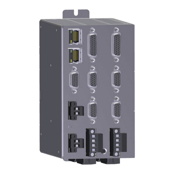
ELECTRICAL INSTALLATION Connectors Connector specifications are in this section. The following figure shows the name and location of the connectors. I/O A ETHERNET I/O B ENC 8 – Auxiliary Encoder ENC - Motor Feedback Encoder 0 Encoder 1 ENABLE - Enable Input Encoder 2 Encoder 3 CTRL- Control Power... -
Page 22: Ctrl - Control Power Connector
ELECTRICAL INSTALLATION CTRL - Control Power Connector The Control power connector provides power for: • Logic for the controller and all drives • Communications • Encoders, halls and motor thermal sensors • I/O logic and 24VDC output power • Brake relays Control Power Connector Description Specification... -
Page 23: Control Power Led
ELECTRICAL INSTALLATION Control Power LED The Control power LED indicates the operating status of the controller. Color Status Control Power is off. Booting (less 2 seconds) Green Ready ACR7000 Servo Controller Installation Guide 23... -
Page 24: Enable - Enable Input Connector
ELECTRICAL INSTALLATION ENABLE – Enable Input Connector The Enable Input must be connected to 24VDC in order to enable/power the motors. If the input goes inactive, that inactive state is latched and the ACR7000 reacts by doing the following: • Disabling the drives, no current to the motors •... -
Page 25: Mtr Pwr - Motor Input Power Connectors
ELECTRICAL INSTALLATION MTR PWR - Motor Input Power Connectors The Motor Input power connectors provide input power for the servo motors. The number of motor connectors is dependent on the controller configuration. Each MTR PWR connector is dedicated to a pair of specific axes. These connectors are removable. -
Page 26: Enc - Encoder Connectors
• TE Connectivity AMP Part Number 1658670-2 Mating connectors are not provided with the drive. Parker cables are available with mating connectors attached. IMPORTANT: Encoder inputs use a SN65C1168E differential line receiver. Parker Hannifin recommends 65C11 (or compatible) differential line driven encoders. -
Page 27: Encoder Connector (0-7) Pinout
ATTACH AXIS0 ENC1 DAC0 ENC0 assigns ENC1 as the position feedback source for motor 0. IMPORTANT: Encoder inputs use a SN65C1168E differential line receiver. Parker Hannifin recommends 65C11 (or compatible) differential line driven encoders. Single ended encoders are supported but not recommended for noisy environments. -
Page 28: Internal Encoder (0-7) Connections
ELECTRICAL INSTALLATION Internal Encoder (0-7) Connections The following figure shows a schematic diagram of the internal connections for the Encoder connectors. Figure 7. - Internal Circuit Diagram for the Motor Encoder Connectors Encoder Inputs (0-7) Encoder input requirements are listed in the table below. Encoder Inputs Description Units... -
Page 29: Motor Thermal Switch Input
ELECTRICAL INSTALLATION Motor Thermal Switch Input The motor thermal input is designed to read a thermistor or thermal switch located in the motor. A constant 2mA current source is driven from the 24V supply through the switch and into ground. The resulting voltage across the switch is scaled by the controller to determine temperature, or switch state, •... -
Page 30: Internal Encoder 8 Connections
ELECTRICAL INSTALLATION Internal Encoder 8 Connections The following figure shows a schematic diagram of the internal connections for the Encoder 8 connector. 30 ACR7000 Servo Controller Installation Guide... -
Page 31: I/O Connectors
ELECTRICAL INSTALLATION I/O Connectors The ACR7000 Servo features inputs and outputs which are accessible using the 26-Pin D-Sub connectors. The 8 axis ACR78V includes connectors A, B, C, D while the 4 axis ACR74V has only A and B. I/O per connector •... -
Page 32: I/O Cable
ELECTRICAL INSTALLATION I/O Cable For preparing your own cable, use differential pair wiring with a minimum of three turns-per-inch (3 TPI). I/O Connector Specification Description Specification Connector Type 26-Pin D-Subminiature (female socket) Manufacturer KYCON or equivalent KYCON Part Number K66X-A26S-NR I/O Connector Specification—Mating Connector Description Specification... -
Page 33: I/O Connector Pinout
ELECTRICAL INSTALLATION I/O Connector Pinout Pinout configuration for the I/O connectors are listed in the following table. I/O Connector Pinout I/O Connector A I/O Connector B I/O Connector C I/O Connector D Signal BIT# Signal BIT# Signal BIT# Signal BIT# Input Input 0 Input 6... -
Page 34: Digital Inputs
ELECTRICAL INSTALLATION Digital Inputs Ten digital inputs present on each I/O connector • Six inputs are general purpose – Pins 1-6 • Four inputs are high speed for encoder position capture functions (INTCAP) – Pins 7-10 • Schmitt Trigger with Zener Diode and RC filter, non-isolated. •... -
Page 35: Outputs-General Purpose
ELECTRICAL INSTALLATION Outputs—General Purpose Four general purpose digital outputs are present on each I/O connector - PINS 12-15 • Current-sinking MOSFET, non-isolated • Overcurrent, Overtemperature, Overvoltage protection. • 24VDC pull-up, 4.75k resistor • Outputs sink current to GND • PIN 19 provide up to 1A for driving outputs – optional Outputs —General Purpose Description Value... -
Page 36: Analog Inputs
ELECTRICAL INSTALLATION Analog Inputs One analog input per I/O connectors, • 12-bit resolution • 0-10VDC range • Differential • Requires ADC ON and ADC MAX commands in controller activate Description Analog in + Analog in - 36 ACR7000 Servo Controller Installation Guide... -
Page 37: Motor Output Power Connectors
ELECTRICAL INSTALLATION Motor Output Power Connectors Each axis has a removeable screw terminal connector which provides output power to the motor. The Motor connector provides terminals U, V, W and for connecting output power to the motors. It also serves to connect an external motor brake to the internal solid-state relays on the two BK terminals. Motor Screw Terminal Connector Specifications Description Specification... -
Page 38: Motor Output Power Connections
Warning: You must connect the Motor Safety Earth conductor terminal, marked GND to the motor cable’s motor-safety-earth wire green/yellow). The following table contains wiring information for making connections with various Parker Hannifin motors series. Wiring to Parker Motors Phase BE/SM with PS cables... -
Page 39: Brake Relay/Brake Power (Optional)
ELECTRICAL INSTALLATION Brake Relay/Brake Power (Optional) The Brake Relay connection (on the Output Power connector) provides a safety feature for your motion control system, particularly for vertical applications. The drive/controller acts as a control switch for the motor brake (if a brake is present). -
Page 40: Brake Relay Connection
ELECTRICAL INSTALLATION Brake Relay Connection Regeneration Protection The ACR7000V Servo drives include internal regeneration dump resistors. Regeneration Specifications Specification Value per axis Voltage threshold, on 60 V Voltage threshold, off 57 V Overvoltage threshold 65 V Peak Dissipation 384W 5.9A 300ms Capacity 168 uF... -
Page 42: Chapter 4 Communications
COMMUNICATIONS CHAPTER 4 Communications 42 ACR7000 Servo Controller Installation Guide... -
Page 43: Overview
Overview The ACR7000 Servo communicates in a standard Ethernet network, thereby providing a direct link for sending commands through the Parker Motion Manager software installed on a PC. This chapter describes how to establish the standard Ethernet connection. The controllers have a dual-stack, standard RJ-45 connector, which provides two communications ports. The two ports act as a hub, with a single IP address. -
Page 44: Ethernet Connector Pinout
COMMUNICATIONS Ethernet Connector Pinout The following table contains the Ethernet connector pinout. RJ-45 Connector Pinout Signal Wire Color Description White with orange Differential Receive positive side Orange Differential Receive negative side White with green Differential Transmit positive side Blue Not used White with blue Not used Green... -
Page 45: Connecting To A Pc
COMMUNICATIONS Connecting to a PC Connect one end of an Ethernet cable to the PC. Connect the other end to one of the ACR7000 Servos two RJ- 45 socket connectors. The two RJ-45 sockets can be used interchangeably. Turn on Control Power to the ACR7000. The ACR7000 has a programmed IP address. - Page 46 COMMUNICATIONS Select Change adapter options. Select Ethernet. More that one Ethernet connections may be displayed. When a cable is inserted to ACR and PC and ACR is powered on the Ethernet connections will show as “Unidentified network” Click Properties. Administrator rights may be required. 46 ACR7000 Servo Controller Installation Guide...
- Page 47 COMMUNICATIONS Select Internet Protocol Version 4 (TCP/IPv4) Click Properties. ACR7000 SERVO Hardware Installation Guide 47...
-
Page 48: Verifying The Ip Address
Verifying the IP Address The following verifies the Ethernet is set up correctly. In Parker Motion Manager, the IP Address box is the value for the controller. In the dialog box, click Connect. In the Terminal Emulator, type VER. If the Ethernet is set up correctly, the terminal emulator reports the firmware version information for the ACR7000 Servo. -
Page 50: Chapter 5 Basic Operation
BASIC OPERATION CHAPTER 5 Basic Operation 50 ACR7000 Servo Controller Installation Guide... -
Page 51: Basic Operation
Parker Motion Manager Parker provides a software development tool to facilitate the setup and programming of the ACR controllers: Parker Motion Manager (PMM). Parker Motion Manager includes a configuration wizard, program editors, a terminal emulator, status panels and software oscilloscopes. - Page 52 BASIC OPERATION Drive/Motor Each axis to be used must have valid motor parameters for proper operation. • Select the motor connected to the axis, matching the part number from the motor nameplate • Select Cooling Method for the motor. (Heatsink in most cases) •...
- Page 53 BASIC OPERATION Feedback Each encoder feedback port is fixed as the commutation source for an axis. That is, ENC1 must be the commutation source for Motor 1 and DAC1 (command output). Axes can be assigned a different ENC as a position feedback source, if that encoder is on the same drive pair (0 and 1, 2 and 3, 4 and 5, 6 and 7).
- Page 54 BASIC OPERATION Fault Position error settings must be non-zero values. Note that units are user programming units. Optionally select inputs used for hardware limit and home operation and soft limit detection. Memory Allocate memory for user programs. Default values are a useful starting point for most applications. These values can be refined later as needed.
-
Page 55: Memory
BASIC OPERATION Memory The ACR7000 Controller utilizes FLASH memory for saving programs and some system and user variables. Storing programs and variable values in FLASH memory requires the use of the FLASH IMAGE command while programs are stopped. Non-Volatile User FRAM store values automatically. ESAVE command is issued with any configuration or program download. -
Page 56: Changing Motor/Drive Parameters
BASIC OPERATION Changing Motor/Drive Parameters In most cases any changes to the motor/drive specific parameters should be performed using the configuration wizard. These parameters can also be changed using the terminal or user programs. Changes are not applied until the DRIVE RES command is issued for the Axis. For example, AXIS1 DRIVE RES. Use the ESAVE command to retain motor/drive parameters. -
Page 58: Appendix A Accessories
APPENDIX A Appendix A Accessories 58 ACR7000 Servo Controller Installation Guide... -
Page 59: Vm26 Breakout Module
APPENDIX A VM26 Breakout Module The VM26 expansion module provides screw-terminal connections for the I/O connections. The VM26 comes with a 2-foot cable (609.6 mm) that provides easy connection between the VM26 module and the axis 26-pin connector. The VM26 expansion module is ordered separately (part number VM26-PM). Notes •... -
Page 60: Cables
APPENDIX A Cables The ACR7000 Servo controllers are programmable products that support a wide array of 3-phase rotary and linear servo motors. The follow cables are used with Parker motors. Cables Feedback Cables Motor Power Cables Motor Family Feedback Type...
Need help?
Do you have a question about the ACR7000 Series and is the answer not in the manual?
Questions and answers