
Related Manuals for Lennox @DNOVA pCO1


Summary of Contents for Lennox @DNOVA pCO1
- Page 1 Manuel d’installation, mise en service et maintenance @DNOVA pCO1 Microprocesseur INNOVA-pCO1-IOM-0907-F lennoxemeia.com...
-
Page 3: Table Of Contents
Index GENERAL DESCRIPTION OF THE APPLICATION ........... 3 Program main functions....................... 3 LCD user interface ........................3 LAN network connections......................3 REGULATION LOGIC ....................4 Temperature control........................4 2.1.1 Close control units with direct expansion coil................4 2.1.2 Other temperature functions....................5 2.1.3 Close control units with two water coils.................. - Page 4 4.1.1 Address configuration of the microprocessor (pCO1)................19 4.1.2 Address configuration of the PGD ..................19 Address configuration of the E2V electronic expansion valve’s driver (EVD) ......19 4.1.3 Boards connection ........................20 4.2.1 Stand alone unit ........................20 4.2.2 Units connected in LAN (max.
-
Page 5: General Description Of The Application
1 GENERAL DESCRIPTION OF THE APPLICATION This program manages “DX” direct expansion or “CW” water coil air-conditioning units and the main features of the application program are described below. 1.1 Program main functions The program main functions are: • control of temperature and humidity inside civil or technological environments •... -
Page 6: Regulation Logic
2 REGULATION LOGIC 2.1 Temperature control The heating and cooling devices are managed based on the temperature value measured by the ambient (or room temperature) probe. The measured temperature is compared to the set temperature (set point); the devices are enabled based on the difference between the two values. The proportional band identifies the air-conditioning unit working range and can take different values in heating and cooling mode. -
Page 7: Other Temperature Functions
2.1.2 Other temperature functions The high and low temperature alarms cause alarm screen signalling and have modifiable delay time. The dehumidification stop differential establishes the minimum temperature below which dehumidification is interrupted. Dehumidification can start again if temperature returns above the value established by the humidification start offset;... -
Page 8: Close Control Units With Single Water Coil
2.1.4 Close control units with single water coil In these close control units, the coil provides for both heating and cooling, depending on the type of water circulating inside it. In practice, the unit works as it was equipped with two different coils. The coil operation depends from a Summer / Winter digital contact that “reports”... -
Page 9: Close Control Units With Direct Expansion Coil
2.2.1 Close control units with direct expansion coil Humidity set HUMIDIFICATION DEHUMIDIFICATION 100% 100% Ambient 48.0 50.0 52.0 humidity (%) 2.0% 2.0% Humidification proportional band Dehumidification proportional band 1 COMPRESSOR ON-OFF CONTACT + Capacity control, if any Ambient 48.0 50.0 52.0 humidity (%) 0-10Volt MODULAT. -
Page 10: Close Control Units With Water Coils
2.2.3 Close control units with water coils In these close control units, the cold water coils provide for dehumidification. For any information about their operation, refer to the previous paragraph. The following diagrams show the dehumidification devices action. The percentage values indicate the modulating valves opening range. Please note that the dehumidification cold water coils are enabled at 100%, not in modulating mode, in case of both threeposition and 0-10Volt valves. -
Page 11: Recovery Without Cooling Devices
2.3.1 Recovery without cooling devices As shown in the previous diagram, the recovery coil only is enabled, whereas the conventional cooling devices are not switched on; as it can be noted in the following diagram, the recovery coil takes up the entire cold proportional band. -
Page 12: Recovery With Cooling Devices On Close Control Units With Water Coils
Temperature set HEAT. COOLING 100% 22.5 23.0 23.5 26.5 0.5°C 0.5°C 3°C Ambient Dead z. Dead z. Cold proportional band temp. (°C) RECOVERY COIL On-Off 1 COMPRESSOR 0-10Volt 23.0 23.5 24.6 24.9 26.5 Ambient temp. (°C) RECOVERY COIL On-Off COMPR. 1 COMPR. -
Page 13: Outlet Limit
2.4 Outlet limit This function prevents too cold air from circulating in the environment, thus safeguarding health of any exposed person. A temperature probe must be positioned on the air-conditioning unit outlet and parameters “Outlet set point” and “Outlet differential” shall be set. Such parameters identify a limiting zone, as shown in the following diagram: Outlet set 100%... -
Page 14: Condenser Fans
2.5 Condenser fans Condensing pressure control is available on DX type units, in which fans are managed based on condensing coil pressure and compressors state. Fans are enabled by 0-10V modulating or digital outputs. Control is based on the condensation set point and differential, as shown in the following diagram: Condensation set CONDENSATION HP PREVENT... -
Page 15: Prevent Function
In case no probe is present, fans are enabled simultaneously with the compressors; in case of single coil, fans are enabled when at least one compressor is on; in case of separated coils, each compressor controls the fans of its own circuit. 2.5.3 Prevent function High pressure alarm prevention with compressors stopped. -
Page 16: Compressors
2.7 Compressors Compressors are managed in ON-OFF mode. Maximum 2 compressors can be present. 2.7.1 Rotation Compressors rotation follows the F.I.F.O. (first in, first out) logic. The first compressor turned on is the first to turn off, the first compressor turned off is the last to turn on. This logic allows comparing the compressors working hours and obtaining the same ageing. -
Page 17: Heaters
To start the compressor again, the user has to rearm the alarm manually by pushing the display Alarm button, provided that the pressure switch has rearmed energising the digital input. After the compressor has turned off, timing is enabled; for this reason, after alarm rearming, the compressor could not immediately turn on again. -
Page 18: 0-10Volt Valves
REALIGNMENT As there is no feedback to define precisely the valves opening range, the program cannot easily manage the three-position valves. A slight difference between the time calculated by the program and the relays enabling time or a mechanical friction preventing the valves from moving freely may originate discrepancy between the valves actual opening range and the range calculated by the program. -
Page 19: The User Interface
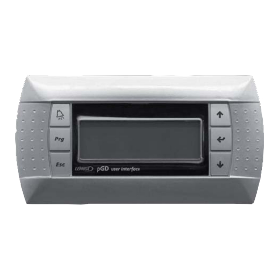
3 THE USER INTERFACE The provided user interface PGD is equipped with a LCD display (4 rows x 20 columns). and with 6 keys. It allows carrying out all program operations. The user interface allows displaying the unit working conditions at any time and modifying the parameters;... -
Page 20: Remote User Interface
3.2 Remote user interface 3.2.1 Without local display Remote display cable: 6 wires, with RJ11 Remote display connectors. Microprocessor pCO1 wall mounted NOTE: the cable is different from the standard telephone cable because in the remote display cable the connectors are reversed. Unit 3.2.2 With local display Local display... -
Page 21: Board Configuration And Connection
4 BOARD CONFIGURATION AND CONNECTION The LAN network identifies a physical connection between the microprocessor, the display and the drivers for the electronic expansion valves. This connection allows exchanging variables from a board to another, according to a logic established by the software, to make them work together in a functional way. The address of the boards must be configure even in stand alone unit. -
Page 22: Boards Connection
4.2 Boards connection The electrical connection among boards is executed using the following two type of cables: Display connection For the connection of the display is necessary to use a cable with 6 wires and RJ11 connectors; the cable is different from the standard telephone cable because in the display cable the connectors are reversed. -
Page 23: Lan Status
Unit 6 Unit 7 Unit 8 The address of the microprocessor can be read from the main screen in the lower right corner. The display with address 32 allows controlling all boards without requiring other displays or in addition to the other displays;... -
Page 24: Program Download From Computer
3. Insert the key into the corresponding slot. 4. Press Up and Down together in the display and switch the board on. 5. Check that the red key LED comes on. 6. Wait until the upload request is displayed on the LCD, then release the buttons and confirm by pressing Enter;... -
Page 25: Language Selection
4.3.4 Language selection English is the language automatically selected, but it can be changed into: Italian, French, German, Spanish. To modify the language, operate as follows: 1. Press the PROGRAM key, select the MAINTENANCE item and press ENTER 2. Press ENTER in the screen A0, and UP or DOWN to modify the language 3. -
Page 26: Alarm Data Logging
No water inside humidifier cylinder No current in humidifier Clock card not present / faulty Circuit 1 high pressure Compressor 1 Circuit 2 high pressure Compressor 2 Water under floor Auxiliary alarm Compressor 1 high pressure + thermal Compressor 1 Humidifier working hours threshold reached Compressor 2 high pressure + thermal Compressor 2... - Page 27 Whenever an alarm goes off, the following air-conditioning unit data are stored for each alarm: alarm description time date event chronological number (0-100) The event chronological number, displayed in the upper right corner, indicates the event “stay time” compared to the 100 available memory spaces.
-
Page 28: Screens
6 SCREENS The screens are divided into these categories: MAINTENANCE: checking the devices periodically, calibrating the connected probes, modifying the working hours and managing the devices manually. PASSWORD = 105 PRINTER: printing the list of parameter only with a special version of display. NO PASSWORD INPUT/OUTPUT: allow to show the digital and analog input/output values. - Page 29 MANUFACTURER PSW Z0 CONFIGURATION C0 INITIALISATION V0 CAREL EXV DRIVER F0 PARAMETERS G0 TIMING T0 INNOV@-pCO1-IOM-0907-E...
-
Page 30: List Of Parameters And Default Values
7 LIST OF PARAMETERS AND DEFAULT VALUES The table below lists the parameters in the program, together with the following information: screen code (the screen code is displayed at the top right) to assist the identification of the parameter, the default value, the minimum and maximum limits (range), and the unit of measure. - Page 31 PARAMETER DESCRIPTION SCREEN DEFAULT SPECIAL VALUE RANGE Enable temperature / humidity / On-Off time No / No / No No-Yes bands Start and end hour for On-Off time bands F1-1and 9 / 13 / 14 / 21 0-23 hours F1-2 Start and end minutes for On-Off time bands F1-1 0 / 0 / 0 / 0 0-59...
- Page 32 PARAMETER DESCRIPTION SCREEN DEFAULT SPECIAL VALUE RANGE Number of rings for analogue modem Password for supervisor remote connection 0-9999 Type of analogue modem Tone Tone-Pulse Enter new user password ---- 0-9999 Manufacturer Menu Enter manufacturer password ---- 0-9999 CONFIGURATION --> Enable BMS No-Yes Enable printer...
- Page 33 PARAMETER DESCRIPTION SCREEN DEFAULT SPECIAL VALUE RANGE Minimum and maximum value measured by the 0.0 / 100.0 0-100.0 humidity probe Enable pressure probe 1 No-Yes 0-1V, 0-10V, Type of signal pressure probe 1 Current Current Minimum and maximum value pressure probe 1 0.0 / 30.0 -20.0 - 50.0 Enable pressure probe 2...
- Page 34 PARAMETER DESCRIPTION SCREEN DEFAULT SPECIAL VALUE RANGE High conductivity alarm threshold 2000 0-2000 uS/cm Drain time as % of the manufacturer value 50-200 Drain frequency as % of the manufacture value 50-200 High pressure alarm set point 23.5 -99.9 - 99.9 High pressure alarm differential -99.9 - 99.9 Condensing (pressure) setpoint...
- Page 35 PARAMETER DESCRIPTION SCREEN DEFAULT SPECIAL VALUE RANGE MOP threshold integration time 0-25.5 seconds High condensing temp. protection threshold 63.0 0-99.9 ºC Integration time for high condensing temp. 0-25.5 seconds threshold High suction temperature threshold 30.0 0-100.0 ºC Custom Valve: minimum steps 0-8100 Custom Valve: maximum steps 1600...
-
Page 36: Architecture Of The Control System
8 ARCHITECTURE OF THE CONTROL SYSTEM 8.1 Microprocessor layout Connector description connector to the power supply [G(+), G0(-)]; fuse 250 Vac, 2A delayed (T2 A); universal analog inputs NTC, 0/1 V, 0/5 V, 0/20 mA, 4/20 mA; passive analog inputs ON/OFF;... -
Page 37: Configuration List
8.2 Configuration list The pCO1 boards allow managing both “DX” direct expansion and “CW” water coil air-conditioning units. When started, the program recognises the board type and size, consequently prearranging inputs and outputs, also based on the air-conditioning unit type (DX or CW) established in the Manufacturer branch. Note: For the input/output configuration see the electrical diagram. -
Page 38: Accessories
MOP (High evaporation pressure, with integral time and adjustable threshold) HiTcond (High condensation pressure that can be activated only by condensation pressure probe read by pCO, with integral time and adjustable threshold). In the parameter table, the control parameters, with the thresholds and the default values, are described. 8.3.2 Accessories SERIAL CARDS The Rs485 serial card allows interfacing pCO1 boards directly to a Rs485 network. -
Page 39: Built-In Humidifier
8.3.3 Built-in humidifier Integrated management of a Carel immersed electrode humidifier. The pCO1 boards manage all the functions, from the reading of the humidifier parameters to the control of the devices (fill, drain, output) by relay. The humidifier parameters (current, conductivity, level) are not read directly, but rather using an elettronic card. - Page 40 HiNet supervising systems It allows air-conditioning systems to be monitored and controlled using a simple Internet browser: the pages displayed on the PC are in HTML format, the language of the worldwide web. RS485 serial line Connected by: - analog telephone line - gsm line - ethernet Local Supervision PC...
-
Page 41: Gsm Protocol
The following protocols are used to ensure connectivity to the other systems: - Carel proprietary (with HiNet supervision system, N = 200) - Modbus (with gateway for Basic Control, N = 16; integrated for Advanced Control, N = ) - Bacnet (with gateway, N = 8) - TCP/IP (with web-gate, N = 16) - Echelon LonWorks (only with Advanced Control) - Trend (only with Advanced Control) -
Page 42: Examples Of Installation
9.3 Examples of installation The connection of pCO1 boards in LAN network allows for the following functions: 1. balancing air-conditioning units working hours by spare units (in stand-by mode) rotation. 2. spare units start-up in case other units stop due to serious alarms or black-out. 3. -
Page 43: Automatic Start And Stand-By Units
9.5 Automatic start and stand-by units The boards connected with LAN network may be managed directly by the program under “critical situations”, that is in case of failure (alarms, black-out…) or due to “Rotation” and “Forcing” functions. The program acts based on some parameters that can be displayed and modified on the board with LAN address 1: ... -
Page 44: Fixed-Hour Rotation
9.5.3 Fixed-hour rotation A system consisting of both running and stand-by units is subject to unbalance in the working hours, causing running units to age faster than stand-by ones. To obviate this problem, LAN network can provide for units rotation, favouring balancing in the working hours. In practice, rotation sets a running unit to stand-by mode and starts a stand-by unit. -
Page 45: Technical Data
9.7 Technical data General specifications operating conditions -10T60 °C 90% R H not condensing protection rating IP20, IP40 on front panel only heat and fire resistance class class D (UL94 - V0) Immunity against over voltages Class 1 number of manoeuvring cycles of automatic 100 000 operations (e.g.: relay) Class and structure of software... - Page 48 PORTUGAL +33 4 72 23 20 00 +351 229 066 050 Pour respecter ses engagements, Lennox s’efforce de fournir des informations les plus précises. Néanmoins, les spécifi cations, valeurs et dimensions indiquées peuvent être modifi ées sans préavis, sans engager la responsabilité de Lennox.
Need help?
Do you have a question about the @DNOVA pCO1 and is the answer not in the manual?
Questions and answers