Sign In
Upload
Manuals
Brands
Lennox Manuals
Controller
PRODIGY2.0
User Manuals: Lennox PRODIGY2.0 HVAC Control System
Manuals and User Guides for Lennox PRODIGY2.0 HVAC Control System. We have
1
Lennox PRODIGY2.0 HVAC Control System manual available for free PDF download: Application Manual
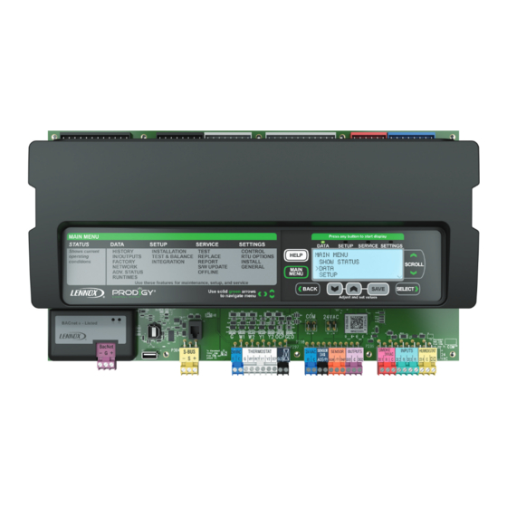
Lennox PRODIGY2.0 Application Manual (167 pages)
M3 UNIT CONTROLLER
Brand:
Lennox
| Category:
Controller
| Size: 1 MB
Table of Contents
Table of Contents
1
1 Prodigy 2.0 - M3 Unit Controller Description
7
Unit Sizes
7
Add-On Controllers
7
M3 Unit Controller Layout and Connections
8
2 Main Controller Operation
9
Control Type - Thermostat
9
Cooling Stages
9
Heating Stages
10
System Mode - Room Sensor Backup Mode Set Points
11
Network Control Panel
11
Room Sensor Back-Up Modes
11
Room Sensor Back-Up Mode Set Points
12
L Connection Network Back-Up Mode Requirements
13
Heating and Cooling Stages in Room Sensor Mode
13
Energence LC/LG -036 through -074U (Ultra-High Efficiency Units)
13
Start-Up Delay in Room Sensor Mode
14
Blower Operation (Occupied) in Room Sensor Mode
14
Room Sensor Parameters
14
3 Unit Component Operation
16
Compressor Protection and Delays
16
Compressor Minimum Run-Time and Off-Delay
16
All Energence LC/LG Ultra-High Efficiency Units
16
All Other Energence Models
16
Compressor on Delay
16
Freeze-Stats (S49, S50, S53 and S95)
16
Thermal Protection Switches (S5, S7, S8, S31 and S180)
16
Energence Ultra-High Efficiency Units (3- to 6-Ton)
17
Tandem Compressors - Energence Ultra-High Efficiency Units (7-1/2 to 12-1/2-Ton)
17
Tandem Compressors - Energence Ultra-High Efficiency Units (15- and 20-Ton)
17
High Pressure Switches (S4, S7, S28 and S96)
17
Energence Ultra-High Efficiency Units (7-1/2 to 12-1/2 Ton)
17
Energence Ultra-High Efficiency Units (15- and 20-Ton) - Tandem Compressors Units
17
Low Pressure Switches (S87, S88, S97 and S98)
17
Loss of Power Detection (Single-Phase Units Only)
18
Gas Units Burner Protection and Delays
18
Flame Roll-Out Switches (S47 and S69)
18
Combustion Air Inducer (CAI) Proof Switches (S18 and S45)
18
Open Proof Sequence of Operations
18
Open Proof Alarms
18
Closed Proof Sequence of Operations
18
Closed Proof Alarms
18
Gas Valve Sensor Activation Feedback
19
Gas Heat Valve Delays
19
Miscellaneous Components
19
Thermostat Bounce Delay (Wired Thermostat Mode Only)
19
Return Air Temperature Limits
19
Smoke Detector (A171 and A172 - Optional)
19
Safety Switch Input (A42-Optional)
19
Air Flow Proving Switch (S52 - Optional)
20
Dirty Filter Switch (S27- Optional)
20
Blower Overload Relay Switch (S42 - Optional)
20
Overflow Switches (S149 / S179 - Optional)
20
Blower On-Delay
20
Blower Off-Delay
20
Unoccupied or Night Setback Mode
21
Wired Thermostat Mode
21
Room Sensor Mode
21
Gas and Electric Heat Warm-Up Mode (During Occupied Time Period)
21
Cool-Down Delay (During Occupied Time Period)
21
Gas Heat Operation-Gas Units
22
Heat Speeds
22
Electric Heat Operation-Electric / Electric Units
22
Electric Heat Stage Delay Operation
22
Primary or Secondary Limits
22
4 Sensors
23
Temperature Sensors - Provided with Unit
23
Room Sensor - Optional
23
Relative Humidity Sensor - Optional
23
Carbon Dioxide (Indoor Air Quality) Sensor - Optional
23
Supply Static Pressure Sensor - Optional
24
Enthalpy Sensor - Optional
24
Economizer Differential Pressure Sensor - Optional
24
5 Outdoor Fan Operations
25
High Ambient Conditions
25
Energence Ultra-High Efficiency (7-1/2- to 20-Ton)
25
Normal Ambient Conditions
25
Energence Ultra-High Efficiency (3- to 6-Ton)
25
Energence Ultra-High Efficiency (7-1/2- to 12-1/2 Ton)
25
Energence Ultra-High Efficiency (15- and 20-Ton)
25
Low Ambient Conditions (S11, S84, S85 and S94)
25
Energence Standard Efficiency (3- to 5-Ton) and High Efficiency (6-Ton)
25
Energence High Efficiency (3- to 5-Ton)
25
Compressor / Fan Configurations
26
Low Ambient Outdoor Fan Control and Cycling
27
Energence a Box Standard, High and Ultra-High Efficiency Units (3-, 4-, 5- and 6-Ton)
27
Energence B Box Standard, High and Ultra-High Efficiency Units (7.5-, 8.5-, 10-, 12- and 12.5-Ton)
28
Energence C Box High and Ultra-High Efficiency Units (13-, 15- and 20-Ton)
29
Energence C Box Standard and High Efficiency Units (17.5-, 20- and 25-Ton)
31
6 Dehumidification Operation
33
Supermarket Reheat Operation Settings
33
Humiditrol Dehumidification Operation - (Humiditrol® Reheat)
33
Third Party Digital Input to Control Dehumidification
35
Outside Air for Dehumidification
35
Selecting Minimum Low and Minimum High Damper Positions
35
Compressor and Humiditrol Operation
36
7 Increased Dehumidification Operation - Energence Ultra-High Efficiency (3- to 6-Ton)
43
Increased Dehumidification in Wired Thermostat Mode
43
Increased Dehumidification in Room Sensor Mode
43
Increased Dehumidification Without a Cooling Demand
43
Increased Dehumidification with a Cooling Demand
43
How to Enable or Disable Increased Dehumidification Mode
44
8 Economizer
45
General
45
Enabling Economizer and Settings
45
Damper Operation During Free Cooling
45
Free Cooling Compressor Lockout Mode and Low Ambient Set Point
45
Outdoor Air Suitable for Free Cooling
45
Enthalpy Set Point
46
Free Cooling Damper Maximum Position
46
Minimum Damper Position
46
Closing Damper and Calibration
46
Motorized Outdoor Air Damper
46
Economizer Checkout
47
9 Demand Control Ventilation (DCV)
49
General
49
Default Operation
49
Maximum and Minimum Demand Control Ventilation Damper Settings
49
Parameter Adjustments
50
Set Point Control Option
50
Determining Indoor Air Quality Inputs
51
10 Outdoor Air Control (OAC)
52
11 Building Pressure Control (BPC)
53
12 Power Exhaust Operation
54
13 Supply Air Delivery
55
Blower Delays
55
Gas / Electric Units
55
Electric / Electric Units
55
Cooling Operation
55
Supply Constant Air Volume (CAV) Control Mode
55
Supply Multi-Stage Air Volume (MSAV) Control Mode
55
Variable Frequency Drive Control
55
Supply Constant Air Volume (CAV) with Zone Bypass Damper Control
56
Bypass Damper Actuator
56
Analog Output Control
57
Supply Manual Reset - Parameter 41
57
Supply Proportional Constant (P) - Parameter 31
57
Supply Integral Constant (I) - Parameter 32
57
Supply Derivative Constant (D) - Parameter 33
57
Tuning
58
14 Discharge Air Control
59
Cooling
59
Discharge Air Control Cooling (DACC) Outdoor Air Temperature Reset
60
Discharge Air Control Cooling (DACC) Return Air Temperature Reset
61
Discharge Air Control Cooling (DACC) Total Reset Limit
62
Heating
62
Discharge Air Control Heating (DACH) Outdoor Air Temperature Reset
63
Discharge Air Control Heating (DACH) Return Air Temperature Reset
63
Discharge Air Control Heating (DACH) Total Reset Limit
64
15 Third-Party Zoning
65
Air Delivery Operation
65
Occupied /Unoccupied Operation
65
Cooling Operation
65
Discharge Air Control Cooling Outdoor Air Reset
65
Discharge Air Control Cooling Return Air Reset
65
Heating Operation
65
Discharge Air Control Heating Outdoor Air Reset
66
Discharge Air Control Heating Return Air Reset
66
Power Exhaust Operation
66
Supply Bypass Damper Control
66
16 Bacnet
67
M3 Unit Controller Bacnet® Module
67
Recommendations
67
Default Settings
67
Analog Output Objects
68
Analog Value Objects
69
Analog Input Objects
70
M3 Unit Controller Bacnet Module Installation
74
Comfort Sensors
75
17 Lontalk
76
Setup
76
Comfort Sensors
76
50 L Connection Network
77
Controllers
77
19 Load Shedding Options
78
20 Service Relay
79
Service Relay Operation
79
System Relative Humidity Options
79
System Indoor Air Quality / Carbon Dioxide Options
79
System Outdoor Air Temperature Operation
79
21 Advanced Airflow System (Smart Airflow™)
81
Calibration
81
Supply Airflow Measurement and Control
81
Outdoor Airflow (OA) Measurement and Control
82
Ventilation Errors
82
Damper Diagnostics
82
22 Sequence of Operation
83
Unit Controller Control Modes
83
Unit Controller in Room Sensor Mode
83
Unit Controller in Thermostat Mode
83
Operations Common to All Rooftop Units
85
Occupied Demand
85
Demand Control Ventilation (DCV)
85
Fresh Air Tempering (FAT)
85
Discharge Air Cooling Reset Operation
86
Discharge Air Heating Reset Operation
86
Damper Position Control of Exhaust Fan (Building Pressure)
86
CAV Units in Single-Zone Applications with a Lennox Room Sensor
87
Unit Controller Operation (4-Heat / 4-Cool)
87
Ventilation Demand
87
Cooling Demand
87
Cooling Demand with Economizer
87
Heating Demand (General Operation)
87
Heating Demand (Electric)
87
Humiditrol Dehumidification Operation - Dehumidification Demand
88
Humiditrol Dehumidification Operation - Cooling Demand Only
88
Humiditrol Dehumidification Operation - Cooling and Dehumidification Demand
88
CAV Units in Single-Zone Applications - Wired Thermostat or Third-Party Unit Controller
88
Unit Controller Operation (2-Heat / 2-Cool)
88
Ventilation Demand
88
Cooling Demand
88
Cooling Demand with Economizer
89
Heating Demand (General Operation)
89
Heating Demand (Electric)
89
Humiditrol Dehumidification Operation - Dehumidification Demand
89
Humiditrol Dehumidification Operation - Cooling Demand Only
89
Humiditrol Dehumidification Operation - Cooling and Dehumidification Demand
90
Discharge Air Temperature Control (4-Heat / 4-Cool)
90
Unit Controller Operation
90
Ventilation Demand
90
Cooling Demand
90
Cooling Demand with Economizer
90
Heating Demand (General Operation)
91
Heating Operation (Electric)
91
Bypass Zoning Applications (2-Heat / 2-Cool)
91
Unit Controller Operation
91
Unit Sequence of Operation
91
Supply Duct Bypass Damper
91
Bypass Zoning Applications (4-Heat / 4-Cool)
92
Unit Controller Operation
92
Unit Sequence of Operation
92
Supply Duct Bypass Damper
92
23 M3 Unit Controller Inputs and Outputs
93
24 M3 User Interface Menu Tree and Display Status Screen
94
Menu Tree (Level 1)
94
Menu Interface Details
95
Show Status
95
Data
95
Setup
98
Service
101
Settings
103
System Status Screen
107
Network Status
107
Unit Operation
107
Alarm Status Display
107
Normal Mode and Status Messages
108
LED Operations
109
25 Model Number and Configuration ID 1 and 2
110
Model Number
110
Configuration ID 1
111
Configuration ID 2
112
26 M3 Unit Controller Parameters
113
Reset to Factory Parameters
113
Unit Controller PC Software
113
27 M2 ECTO to M3 Parameter Cross-References
140
28 Events and Alarms
147
Phase - Voltage Detection
147
M3 Unit Controller Alarm and Event Codes
147
29 Abbreviations
157
30 Controller Signal References
159
M3 Unit Controller
159
GP3 Control
162
C3 Control
162
31 Prodigy 2.0 Release History
164
Advertisement
Advertisement
Related Products
Lennox @DNOVA pCO1
Lennox Prodigy
Lennox PR4290
Lennox Magic-Pak PWC18E14.7
Lennox Merit Plus MP-420D
Lennox MERIT Plus MPB3530CNE-B
Lennox Merit Plus MPD-4035CPM-B
Lennox Merit Plus MPDT-3328CNE-B
Lennox Merit Plus MPDR-3328CPE-B
Lennox Merit Plus MPDR33RNM
Lennox Categories
Furnace
Air Conditioner
Heat Pump
Indoor Fireplace
Thermostat
More Lennox Manuals
Login
Sign In
OR
Sign in with Facebook
Sign in with Google
Upload manual
Upload from disk
Upload from URL