Advertisement
Quick Links
Advertisement

Related Manuals for Lennox e-Lite LV-CW02


Summary of Contents for Lennox e-Lite LV-CW02
- Page 1 e-Lite LV-CW02 | WIRED CONTROLLER Installation and Operation Manual LV-CW02-IOM-20.04-E...
- Page 3 ● Read this manual carefully and be sure you understand the information before attempting to use the controller. ● Keep this manual where it is readily accessible after reading it through. ● If another user operates the controller in the future, be sure to hand over this manual to the new user.
- Page 4 Contents Installation ......................1 1. Safety Precautions ..................1 2. Accessories ..................... 3 3. Installation Procedure..................4 Operation ......................9 1. Safety Precautions ..................9 2. Parts of the Wired Controller ................. 11 3. Icons in the Display ..................13 4.
- Page 5 Installation 1. Safety Precautions Please read these Safety Precautions carefully before installing the wired controller. This manual classifies the precautions into WARNING and CAUTION. They both contain important information regarding safety. Be sure to follow all the precautions below. Meaning Identifier Failure to follow these instructions properly may result in personal...
- Page 6 ● Be sure to use only the specified accessories and parts for installation work. Failure to use the specified parts may result in the unit falling down, water leakage, electric shocks or fire. ● Install the wired controller on a foundation strong enough to withstand the weight of the wired controller.
- Page 7 2. Accessories Please check that you have all the following parts. Table 2.1 Name Remarks Schematic Qty. Used to install the wired Philips head screw, controller on the electrical M4X25mm Used to install the wired Plastic support bar controller on the electrical φ5X16mm Operation and Installation Manual...
- Page 8 3. Installation Procedure 3-1 Determine Where to Install the Wired Controller Make sure to refer to "1. Safety Precautions" to determine the location. 3-2 Structural Dimensions 20mm 86mm FOLLOW ME 60mm Figure 3.1 Figure 3.2 3-3 Rear Cover Installation 3-3-1 Insert a small slotted-head screwdriver into the bottom slot of the wired controller and rotate in the direction indicated to remove the rear cover of the wired controller.
- Page 9 Warning • When using the small slotted screwdriver to open the rear cover of the wired controller, be careful not to damage the PCB inside. • Do not touch the PCB of the wired controller. 3-3-2 Use a cutting tool to adjust the height of the two plastic support bars (accessory 2) to match the standard length of the screw pillars of the electrical box to the wall surface.
- Page 10 3-3-4 Take the shielded wiring that has been pre-embedded in the wall, and thread it through the wire hole of the rear cover. Use the Philips head screws (accessory 1) to fix the rear cover of the wired controller to the electrical box via the support bars. Make sure that the rear cover is not deformed after being installed (see Figure 3.6).
- Page 11 3-4-2 Communication wiring • The communication between the indoor unit and wired controller is bi-directional communication. The parameters displayed on the wired controller are refreshed in real time according to changes in the parameters of the indoor unit. • X1 and X2 are terminals to connect the indoor unit and wired controller. There is no polarity between X1 and X2.
- Page 12 P/Q/E P/Q/E P/Q/E P/Q/E X1/X2 X1/X2 X1/X2 X1/X2 Not allowed X1/X2 ○○○ 2-to-1 1-to-1 2-to-1 Two controllers to one indoor unit connection method Figure 3.8 • For the two controllers to one indoor unit connection method, two wired controllers control the same indoor unit, where one controller will be the "Main", and the other be the "Secondary".
- Page 13 X1 X2 Figure 3.9 Figure 3.10 △ Caution • During installation, reserve a certain length for the connecting shielded wiring to make it easier to remove the wired controller for maintenance. Operation 1. Safety Precautions This controller is not intended to be used by persons, including children, with reduced physical, sensory or mental capabilities or lack of experience and knowledge, unless they are supervised or have been given instructions on how to use the controller by a person responsible for their safety.
- Page 14 Meaning Identifier Failure to follow these instructions properly may result in personal Warning injury or loss of life. Failure to observe these instructions properly may result in property Caution damage or personal injury, which may be serious depending on the circumstances.
- Page 15 Caution ● Do not play with the wired controller. Accidental operation by a child may result in impairment of bodily functions and harm health. ● Never disassemble the wired controller. Pressing the interior parts may result in electric shocks or fire. Consult your dealer or authorized contractor for internal inspections and adjustments.
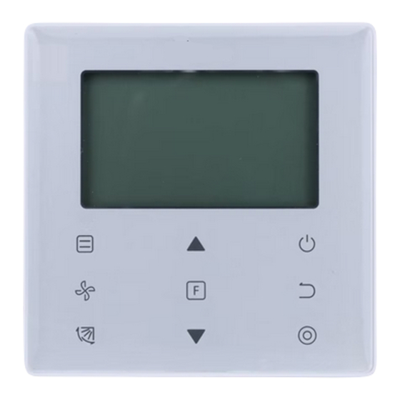
- Page 16 Table 4.1 Button Functions Mode To set the operating mode: Auto → Cool→ Heat→ Dry→ Fan Fan speed To set the fan speed. Swing To set the swing function. To switch to functions that can be set in the current mode. Function Adjust upwards To adjust temperature setting and timing (for timer) upwards.
- Page 17 3. Icons in the Display ⑤ ① ⑦ ② ⑧ ⑨ ⑩ ③ ④ ⑥ ① Clean filter reminder indicator ② Fan speed ③ Indoor unit ON/OFF ④ Swing ⑤ Operating mode ⑥ Function Lock indicator Signal transmission indicator ⑦ ⑧...
- Page 18 Figure 6.1 1) Press (ON/OFF) button, and the Operating Indicator " " on the wired controller will light up, while the ON/OFF icon " " of the indoor unit on the display will spin to indicate that the indoor unit has started running. (see Figure 6.1) 2) Press (ON/OFF) button again, and the Operating Indicator "...
- Page 19 Auto →Cool→Heat→Dry→Fan Figure 6.3 In the "Auto", "Cool", "Dry", or "Heat" mode, press ▲ and ▼ buttons to adjust to the setting temperature. (see Figure 6.4) Figure 6.4 Note: • The "Auto" mode is not available for all air conditioner models. •...
- Page 20 In the "Cool", "Heat" or "Fan" mode, press (Fan speed) button to set the operating fan speed (see Figure 6.5). If the wired controller is configured with seven fan speeds, press (Fan speed) button to set the fan speed in turn as shown in Figure 6.6. →...
- Page 21 Press (Swing) button to control the swing of the vertical louver of indoor unit (see Figure 6.8). When the unit is on, the display icon shows the swing angle of the current louver. Press (Swing) button, and the louver switches from the current angle to the angles in turn as shown in Figure 6.9.
- Page 22 Press (Function) button to switch to the function that can be set in the current mode (see Figure 6.10). • Press (Function) button to go to the function setting, and the display on the wired controller will show in turns: " ", "...
- Page 23 4-5-2 Silent The "Silent" function is used to send the "Silent" control signal to the indoor unit. The indoor unit automatically optimizes the noise it generates when it is in the "Silent" state. • Turn on/off the "Silent" function: press (Function) button to switch to the "Silent"...
- Page 24 • Turn on/off the "ECO" function: press (Function) button to switch to the "ECO" function (" " blinks), and press (Confirm) button to turn on the function or (Cancel) button to turn off the function (see Figure 6.14). Start Blink Figure 6.14 Note: •...
- Page 25 The "Follow Me" function of the wired controller is on by default, and its icon lights up when the function is on. 1) Turn off "Follow Me": Press (Swing) and (Confirm) buttons at the same time, and hold for 5 seconds to turn off the "Follow Me" function, and its icon disappear. 2) Turn on "Follow Me": When the "Follow Me"...
- Page 26 Figure 6.16 2) "Timer Off" setting: Once the "Timer On" setting is completed, press (Function) button to go to the "Timer Off" setting, the display will show "0.0h Time Off", and the words "Time Of" will blink. press (Confirm) button to go to the timer setting, and press ▲ and ▼...
- Page 27 4-6 Clean Filer Reminder Figure 6.17 • When the operating time reaches the preset time, the Filter icon " " lights up to remind users to clean the filter. • Press and hold (Swing) button for 5 seconds to remove the Filter icon " ".
- Page 28 • One or more of the following functions of the indoor unit are locked when the icon " " lights up on the display: wireless remote controller, on/off state, lowest cooling set temperature, highest set temperature, mode, fan speed, wired controller lock. •...
- Page 29 Figure 7.1 2. Query and Set the Indoor Unit Address • If the indoor unit has no address, the display will show "FE", and the wired controller will display an E9 error. • Press and hold ▲ and ▼ buttons for 8 seconds to go to the page to set the indoor unit address.
- Page 30 adjust the address to the required value (address range is 0-63). press (Confirm) button to send the current address value to the indoor unit. In 60 seconds, the wired controller will exit the address setting page, or press (Cancel) button to exit the address setting page. •...
- Page 31 Table 5.1 Parameter Parameter Select Default Remarks Code Content Parameters Value If two wired controllers control one indoor unit, F0: Main wired the address must be different controller Address Setting F1: Secondary wired controller Cooling 00: Cooling and Heating Only/Cooling Heating mode is not available in cooling only and Heating setting.
- Page 32 Parameter Parameter Select Default Remarks Code Content Parameters Value Select "On" and the operating indicator will show the Settings to 00: Off ON/OFF state of the indoor unit. turn on/off Select "Off" and the operating indicator will always operating 01: On be off regardless the indoor unit is...
-
Page 33: Table Of Contents
Parameter Parameter Select Default Remarks Code Content Parameters Value Parameter Based on Indoor unit the dial heating switches 00/01/02/ 1 and 5 temperature Value 6°C/ 2°C/ 4°C/ 6°C/ 0°C/ in the 03/04/FF compensation Represents 43°F 36° F 39°F 43°F 32° F main PCB setting of the... -
Page 34: Indoor Unit
Parameter Parameter Select Default Remarks Code Content Parameters Value Common 00: None Indoor unit Indoor Unit: horizontal swing 01: Available setting FAPU: 00 Display of 00: No indoor unit to receive the 01: Yes remote control signals 00: No Buzzer of the indoor unit rings 01: Yes Follow Me in... -
Page 35: Unit
Parameter Parameter Select Default Remarks Code Content Parameters Value Parameter Select opening of electronic Based on the dial expansion valve 00/01/FF Value switches in the in Heating or Represents main PCB of the Standby mode indoor unit Temperature 00: Celsius 00/01 Unit 01: Fahrenheit... - Page 36 1 Once the indoor unit and wired controller communicate successfully, the default parameters of the above table will synchronize to the indoor unit settings. 2 Only for medium static duct unit Capacity 1.8 - 7.1kW 10Pa 20Pa 30Pa 40Pa 50Pa 50Pa 50Pa 50Pa...
- Page 37 4. Query Operations In the main page, press and hold (Fan speed) and (Confirm) buttons at the same time for 5 seconds to go to the query page. You can query the check operation parameters of the outdoor and indoor units as well as the program version of the wired controller. Figure 7.4 Press ▲...
- Page 38 Table 6.1 Parameter displayed on the wired controller during ODU spot check ODU address Outdoor ambient(T4) temperature (°C) T2/T2B average Temp. (corrected) (°C) Main heat exchanger pipe(T3) temperature (°C) Discharge Temp. of compressor A(°C) Discharge Temp. of compressor A(°C) Inverter compressor A current (A) Inverter compressor B current (A) Reserved Fan speed...
-
Page 39: Parameter
Parameter displayed on the wired controller during ODU spot check Inverter-module heatsink Temp. A(°C) Inverter-module heatsink Temp. B(°C) (reserved) Reserved Plate heat exchanger outlet (T6B) temperature (°C) Plate heat exchanger inlet (T6A) temperature (°C) System discharge superheat degree Number of operating indoor units (in case of virtual addresses, this is the number of units with the virtual addresses included) High pressure of system Low pressure of the system (reserved) - Page 40 Parameter displayed on the wired controller during ODU spot check Reserved 2 Reserved 2 Table 6.2 Parameter displayed on the wired controller during IDU spot check IDU communication address Capacity (HP) of IDU IDU network address (the same as the communication address) Set temperature Ts Room temperature T1 Actual T2 indoor temperature...
- Page 41 5. Error Display • When there is a communication error between the wired controller and the indoor unit, the wired controller will show the error code "E9", an indication of a communication failure in wired controller. • When the indoor or outdoor unit fails, the display of the wired controller shows the address of faulty unit(s) in the timer area, and the error code in the temperature area.
- Page 42 Table 7.2 List of ODU error codes: Error Error Definition and Error Error Definition and Description Code Description Code ODU communication fault PTC error Three-phase power supply Error in temperature sensor at T6B phase protection plate heat exchanger outlet Communication error between Error in temperature sensor at T6A indoor and outdoor units plate heat exchanger inlet...
- Page 43 List of ODU error codes: Error Error Definition and Error Error Definition and Description Code Description Code Inverter module protection Inverter module fault fault 3X P2 protection fault in 60 DC bus low voltage protection minutes 3X P4 protection fault in 100 DC bus high voltage protection minutes IDU qty decrease fault...
- Page 44 Troubleshooting Table 8.1 Error code and Possible Causes Possible Solutions description IDU is not powered on Power on the IDU. First power off the IDU, and then check if Wired controller connection error the wired controller connection is correct. No display on the See Section 3.4 on the wiring requirements.
- Page 48 Thank you very much for purchasing our product. Before using your air conditioner, please read this manual carefully and keep it for future reference. Due to LENNOX EMEA ongoing commitment to quality, the specifications, ratings and dimensions are subject to change without notice and without incurring liability.
Need help?
Do you have a question about the e-Lite LV-CW02 and is the answer not in the manual?
Questions and answers