Table of Contents
Advertisement
Quick Links
Advertisement
Table of Contents

Related Manuals for Pixsys ATR 902


Summary of Contents for Pixsys ATR 902
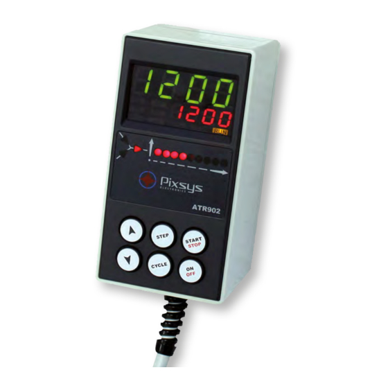
- Page 1 ATR 902 Controller User manual...
-
Page 3: Table Of Contents
Table of contents 1 Safety guide lines ..........................10 2 Model identi cation ...........................10 3 Technical data ............................10 3.1 General features.........................10 3.2 Hardware features........................11 3.3 Software features ........................11 4 Size and Installation ...........................11 5 Electrical wirings ..........................12 5.1 Wiring diagram ..........................12 6 Displays and keys function .......................12 6.1 Numeric indicators (Display) ....................13 6.2 Meaning of Status Lights (Led) ....................13... -
Page 7: Safety Guide Lines
Introduction Thanks for choosing a Pixsys device. The plug-in controller ATR902 is specially dedicated to applications in the glass, metal and pottery industry. This controller provides high accuracy of the programmed ring cycle and reliable monitoring of the temperature. It can store up to 15 completely con gurable programs, each consisting of max. -
Page 8: Hardware Features
3.2 Hardware features AI1 - Con gurable for Accuracy (25°C) Thermocouple +/-0.2 % ± 1 digit (full Sensor input K,S,R,J,T,E,N. scale). Cold junction automatic Cold junction accuracy compensation 0 ... 50°C. 0.1°C/°C 2 Relays con gurable as Contacts: 1A-250V~ for Relay outputs control output and alarm resistive charges... -
Page 9: Electrical Wirings
Electrical wirings This device has been designed and manufactured in conformity to Low Voltage Directive 2006/95/EC , 2014/35/EU (LVD) and EMC Directive 2004/108/EC, 2014/30/ EU (EMC). For installation in industrial environments please observe following safety guidelines: • Separate control line from power wires. •... -
Page 10: Numeric Indicators (Display)
6.1 Numeric indicators (Display) Usually visualizes mesured temperature, it may visualize also (programmed temperature) setpoint value, time elapsed from cycle start, number of 123. 4 operating step or the percentage value of the command output. During con guration it visualizes the value of entering parameter. -
Page 11: Keys
6.3 Keys • In con guration allows to scroll and modify parameters • Scroll cycles to be started or modi ed. • In cycle programming allows to modify time and setpoint values. • Modi es the setpoint during function ( tHEr ). “simple controller”... -
Page 12: Programming And Con Guration
Programming and con guration There are two programming levels: 1. Cycles programming (for operator/user), to enter time/setpoint values for each step of cycle. 2. Con guration (for manufacturer/installer of plant), to enter main parameters (sensor type, output type, intervention type alarm/auxiliary ext.). 7.1 Programming (or modifying) cycle data •... - Page 13 7.1.2 Programming of the step (segment) Press Display Red display visualizes 01-t . STEP Green display shows step time. Increases, decreases value on Enter the step duration in green display. hours:minutes. N.B.:Each cycle is composed of N.B.: Set --.-- for endless time or max.
-
Page 14: Cycle Start
Cycle start 8.1 Start of a cycle and setting of delayed start Red display visualizes stop . Press Display Press CYCLE to scroll the cycles Red display visualizes the cycle ( cy.02 for cycle no. 2 - cy. 1 5 for CYCLE selection. -
Page 15: Simple Controller Function
8.3 Simple controller function When this function is active, the controller cannot manage a step cycle but it regulates according to a single setpoint (programmed temperature) which is selectable by the user. Press stop and follow the points below: Press Display Red display visualizes the selected Increase until visualize tHer . -
Page 16: Manual Tuning
9.3 Manual Tuning This procedure allows user a greater exibility on deciding when to update PID parameters. To enable this function, select man. on parameter 06 tune . To start manual tuning procedure follow the points below (when cycle is running): Press Display Press until red display visualizes tune . - Page 17 Step 3 Step 2 PROCESS Black-out SETPOINT NB: After a power-o the chronometer will restart from 00:00. Step 2 Step 1 Time 9.4.2 Recovery with programmable recovery gradient To enable cycle recovery with a recovery gradient, enter on parameter 22 r.i.cy. a value (degrees/hour if temperature) greater than 1.
-
Page 18: Waiting Step End
9.5 Waiting step end This function has been conceived to control kilns working cycles, whenever the kiln cannot follow gradients programmed by the user. If at step end the di erence between process and setpoint values is greater than the value on parameter 21 m.G.s.e. - Page 19 Con guration for installer To enter con guration parameter it is necessary to stop the controller. Press Display Press for 5”. Green display shows 0000 with 1st digit ashing, red CYCLE display visualizes pass . Flashing digit on green Enter the password 1234 . display changes.
-
Page 20: Table Of Con Guration Parameters
Table of con guration parameters 10.1 1st level parameters Sensor Sen. Select type of sensor. Thermocouple type K. Range: -260..1360°C > Default tc. k Thermocouple type S. Range: -40…1760°C tc. S Thermocouple type R. Range: -40…1760°C tc. r Thermocouple type J. Range: -200…1200°C tc. - Page 21 Command Hysteresis c. HY. Hysteresis in ON/OFF or dead band in P.I.D. for command output. -99.9…+99.9 tenths of degree.> Default: 1.0. Proportional Band P.b. Process inertia in degrees. 0.0 ON/OFF if also t.i. equal to 0. > Default. 0.1…999.9 tenths of degree. Integral Time t.
- Page 22 Special Functions sp.fu. Enables simple thermoregulator function and manual setting of output percentage. (Disabled) No function available. > Default. dis. (Thermoregulator) Enables simple thermoregulator function. tHer. (Manual) Enables manual mode. man. (Thermoregulator and Manual) Enables both simple thermoregula- tH.ma. tor and manual function. Hold Function HLd.F.
- Page 23 Alarm 1 AL. 1 Alarm 1 selection. (Disabled). > Default. Dis. (Absolute Alarm). referring to the process a. aL. (Band Alarm). Command sepoint ± band b. aL. u.d.aL. (Upper Deviation Alarm). Command setpoint + deviation (Lower Deviation Alarm). Command setpoint - deviation L.d.aL.
-
Page 24: 2Nd Level Parameters (For Expert Operators)
Alarm 1 Action Type a. 1 .a.t. De nes alarm action type on operating cycle (No Action). Changes only output related to the alarm. > Default. no.ac. (End Cycle Signal). Cycle ends (STOP) with acoustic and visual e.cY.s. signalling. Changes output related to the alarm, buzzer sounds and on display ashes AL. - Page 25 On/O Key o.keY Sets ON/OFF key functioning. (Disabled). ON/OFF key not working. Dis. (Countdown). Pressing ON/OFF for 3” the device switches-o cntd visualizing a countdown. The restart is done pressing the key for 1’’. > Default. (Fast). Press ON/OFF for 1’’ to switch on/o the controller. fast Led Mode Led.m.
-
Page 26: Alarm Intervention Modes
Max Gap Tune m.G.tu. Selects the max. process-setpoint gap, beyond which the automatic tune recalculates P.I.D. parameters. 0.1…50.0 tenths of degree. > Default: 1.0. Minimum Proportional Band mn.p.b. Selects the proportional band min. value selectable by automatic tune. 0.0…999.9 tenths of degree. > Default: 5.0. Maximum Proportional Band ma.p.b. - Page 27 11.b Band alarm (setpoint-process) Comparison value (Par. 25) PROCESS SETPOINT Alarm can be: Hysteresis • Active outside • Active inside Hysteresis In the gure it is active outside. Time 11.c Deviation alarms Comparison value (Par. 25) PROCESS SETPOINT Alarm can be: Hysteresis •...
-
Page 28: Table Of Anomaly Signals
11.e Auxiliary output related to the step Step 4 Step 3 ON/OFF status of the auxiliary output Step 5 is selectable for each step of each Cycle end Step 2 cycle. The status can be selected also Step 6 Step 1 Operator stop at cycle end. - Page 29 Notes / Updates User manual - ATR902 - 29...
- Page 30 Table of con guration parameters Sensor Sen. O set Calibration o.caL. Gain Calibration G.caL. Upper Limit Setpoint up.L.s. Degree dEGr. Tune Tune Setpoint Deviation Tune s.d.tu. Command Hysteresis c. HY. Proportional Band P.b. Integral Time t. i . Derivative Time t.d.
- Page 31 Cycle 2 Name cY.2.n. Cycle 3 Name cY.3.n. Cycle 4 Name cY. 4 .n. Cycle 5 Name cY.5.n. Max Gap Tune m.G.tu. Minimum Proportional Band mn.p.b. Maximum Proportional Band ma.p.b. Minimum Integral Time mn. i .t. User manual - ATR902 - 31...
- Page 32 Antes de usar el dispositivo leer con atención las instrucciones y las medidas de seguridad contenidas en este manual. Vor der Inbetriebnahme/Verwendung dieses Reglers bitte die in dieser Anleitung enthaltenen Sicherheitshinweise und Angaben sorgfältig lesen. PIXSYS s.r.l. www.pixsys.net sales@pixsys.net - support@pixsys.net online assistance: http://forum.pixsys.net 2300.10.159-RevB Software Rev. 1.03 230617...
Need help?
Do you have a question about the ATR 902 and is the answer not in the manual?
Questions and answers