Table of Contents
Advertisement
Quick Links
Advertisement
Table of Contents

Related Manuals for Supero X11SAE


Summary of Contents for Supero X11SAE
- Page 1 X11SAE X11SAE-F USER’S MANUAL Revision 1.0b...
- Page 2 The information in this User’s Manual has been carefully reviewed and is believed to be accurate. The vendor assumes no responsibility for any inaccuracies that may be contained in this document, makes no commitment to update or to keep current the information in this manual, or to notify any person or organization of the updates.
-
Page 3: Preface
This manual is written for system integrators, PC technicians and knowledgeable PC users. It provides information for the installation and use of the X11SAE/X11SAE-F motherboard. Manual Organization Chapter 1 describes the features, specifications and performance of the motherboard, and provides detailed information on the Intel C236 Express chipset. -
Page 4: Checklist
Supermicro X11SAE/X11SAE-F Motherboard User’s Manual Checklist Congratulations on purchasing your computer motherboard from an ac- knowledged leader in the industry. Supermicro boards are designed with the utmost attention to detail to provide you with the highest standards in quality and performance. -
Page 5: Standardized Warning Statements
Standardized Warning Statements Standardized Warning Statements The following statements are industry-standard warnings, provided to warn the user of situations which have the potential for bodily injury. Should you have questions or experience difficulty, contact Supermicro's Technical Support department for assistance. Only certified technicians should attempt to install or configure components. -
Page 6: Product Disposal
Supermicro X11SAE/X11SAE-F Motherboard User’s Manual ¡Advertencia! Existe peligro de explosión si la batería se reemplaza de manera incor- recta. Reemplazar la batería exclusivamente con el mismo tipo o el equivalente recomendado por el fabricante. Desechar las baterías gasta- das según las instrucciones del fabricante. - Page 7 Standardized Warning Statements 製品の廃棄 この製品を廃棄処分する場合、 国の関係する全ての法律 ・ 条例に従い処理する必要が あり ます。 警告 本产品的废弃处理应根据所有国家的法律和规章进行。 警告 本產品的廢棄處理應根據所有國家的法律和規章進行。 Warnung Die Entsorgung dieses Produkts sollte gemäß allen Bestimmungen und Gesetzen des Landes erfolgen. ¡Advertencia! Al deshacerse por completo de este producto debe seguir todas las leyes y reglamentos nacionales.
-
Page 8: Contacting Supermicro
Supermicro X11SAE/X11SAE-F Motherboard User’s Manual Contacting Supermicro Headquarters Address: Super Micro Computer, Inc. 980 Rock Ave. San Jose, CA 95131 U.S.A. Tel: +1 (408) 503-8000 Fax: +1 (408) 503-8008 Email: marketing@supermicro.com (General Information) support@supermicro.com (Technical Support) Web Site: www.supermicro.com Europe Address: Super Micro Computer B.V. -
Page 9: Where To Find More Information
Contacting Supermicro Where to Find More Information For your system to work properly, please follow the links below to download all necessary drivers/utilities and the user's manual for your motherboard. Supermicro product manuals: http://www.supermicro.com/support/ manuals/ Product Drivers and utilities: ftp://ftp.supermicro.com/ If you have any questions, please contact our support team at support@ supermicro.com. -
Page 10: Table Of Contents
Supermicro X11SAE/X11SAE-F Motherboard User’s Manual Table of Contents Preface Manual Organization ................iii Checklist ..................iv Conventions Used in the Manual ............iv Standardized Warning Statements ............v Battery Handling ............... v Product Disposal ...............vi Contacting Supermicro ..............viii Where to Find More Information............ix Chapter 1 Introduction Overview ................ - Page 11 Table of Contents Removing Memory Modules ............. 2-9 Memory Support ..............2-10 Memory Population Guidelines ..........2-11 Motherboard Installation ............2-12 Tools Needed ............... 2-12 Location of Mounting Holes ........... 2-12 Installing the Motherboard ............ 2-13 Connectors/IO Ports ............. 2-14 Back I/O Panel ..............
- Page 12 Supermicro X11SAE/X11SAE-F Motherboard User’s Manual Jumper Settings ..............2-29 Explanation of Jumpers ............2-29 LAN Enable/Disable ............2-29 Clear CMOS ..............2-30 PCI Slot SMB Enable (JI2C1/JI2C2) ........2-30 BMC Enable (JPB1) ............2-30 Audio Enable (JPAC1) ............2-31 HD Audio Enable (JHD_AC1) ..........2-31 Watch Dog Enable/Disable ..........
- Page 13 Table of Contents System Date/System Time ............ 8 Supermicro X11SAE/X11SAE-F ..........8 BIOS Version ................ 8 Build Date ................9 Memory Information .............. 9 Total Memory ................ 9 Memory Speed..............9 Advanced Setup Configurations ..........10 Boot Feature ................ 10 Quiet Boot .................
- Page 14 Supermicro X11SAE/X11SAE-F Motherboard User’s Manual CPU C-States ..............15 Enhanced C-States .............. 15 C-State Auto Demotion ............15 C-State Un-Demotion ............15 Package C-State Demotion ........... 15 Package C-State Un-Demotion ..........15 C-State Pre-Wake ..............15 Package C-State Limit ............15 Chipset Configuration ............
- Page 15 Table of Contents IPv6 PXE Support ..............26 PXE boot wait time .............. 26 Media detect count .............. 26 Super IO Configuration ............26 Super IO Chip Logical Device(s) Configuration ......26 Serial Port 1 ................ 26 Serial Port 1 Configuration ........... 26 Serial Port 1 ...............
- Page 16 Supermicro X11SAE/X11SAE-F Motherboard User’s Manual COM1 Legacy OS Redirection Resolution ........ 30 COM1 Putty KeyPad ............. 30 COM1 Redirection After BIOS POST ........30 COM2 ................30 COM2 Console Redirection ............ 30 COM2 Console Redirection Settings ........31 COM2 Terminal Type ............31 COM2 Bits Per second ............
- Page 17 Table of Contents Bits Per Second ..............35 Flow Control ............... 35 Data Bits................35 Parity ................35 Stop Bits ................35 ACPI Settings ..............36 ACPI Sleep State ..............36 High Precision Event Timer ........... 36 WHEA Support ..............36 Trusted Computing Configuration ..........
- Page 18 Supermicro X11SAE/X11SAE-F Motherboard User’s Manual Link Status ................. 39 MAC Address ..............39 Event Logs ................40 Change SMBIOS Event Log Settings ........40 Enabling/Disabling Options ........... 40 SMBIOS Event Log .............. 40 Erasing Settings ..............40 Erase Event Log ..............40 When Log is Full ..............
- Page 19 Table of Contents Provision Factory Default Keys ..........45 Enroll All Factory Default Keys ........... 45 Save All Secure Boot Variables ..........46 Platform Key (PK) ............46 Set New Key ..............46 Key Exchange Key ............46 Set New Key ..............
- Page 20 Supermicro X11SAE/X11SAE-F Motherboard User’s Manual Appendix A BIOS Error Beep Codes BIOS Error Beep Codes ............A-1 Appendix B Software Installation Instructions Installing Drivers ..............B-1 Configuring SuperDoctor ® III ..........B-2 Appendix C UEFI BIOS Recovery Instructions An Overview to the UEFI BIOS ..........C-1 How to Recover the UEFI BIOS Image (-the Main BIOS Block) ..
-
Page 21: Chapter 1 Introduction
6th Generation Intel® Core™ i7/i5/i3 series, a single Pentium or Celeron processor, in an LGA 1151 (H4) socket. With the In- tel® C236 Express chipset built in, the X11SAE/X11SAE-F motherboard offers exceptional performance and storage capability for workstation platforms. -
Page 22: Motherboard Features
USB 3.1 'type A' ports on the rear I/O panel Six (6) Front-Accessible USB 2.0 ports on three head- ers on the X11SAE, Four (4) Front-Accessible USB 2.0 ports on two headers on the X11SAE-F, and Four (4) Front Accessible USB 3.0 ports on two headers, on both models. - Page 23 Chapter 1: Introduction Audio One (1) High Definition Audio 7.1 channel connector supported by Realtek ALC888S on the back panel One (1) Front Panel Audio Header Super I/O Nuvoton NCT6776D 128 Mb AMI BIOS SPI Flash BIOS BIOS ® Plug and Play (PnP0, DMI 2.8, PCI 2.3, ACPI 1.0/2.0/3.0, and USB Keyboard ACPI/ASPM Power Management Power...
-
Page 24: Special Features
PC health monitoring in the BIOS can check the RPM status of the cool- ing fans. The onboard CPU and chassis fans are controlled by Thermal Management via SIO (X11SAE) or BMC (X11SAE-F). Environmental Temperature Control The thermal control sensor monitors the CPU temperature in real time and will turn on the thermal control fan whenever the CPU temperature exceeds a user-defined threshold. -
Page 25: System Resource Alert
Chapter 1: Introduction System Resource Alert This feature is available when the system is used with SuperDoctor III in the Windows OS environment or used with SuperDoctor II in Linux. SuperDoctor is used to notify the user of certain system events. For example, you can also configure SuperDoctor to provide you with warnings when the system temperature, CPU temperatures, voltages and fan speeds go beyond predefined thresholds. -
Page 26: Power Supply
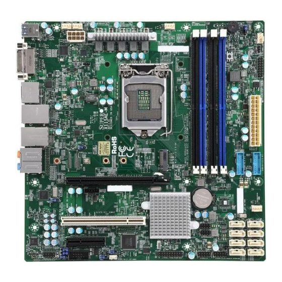
Supermicro X11SAE/X11SAE-F Motherboard User’s Manual 1-7 Power Supply As with all computer products, a stable power source is necessary for proper and reliable operation. It is even more important for processors that have high CPU clock rates. This motherboard accommodates 24-pin ATX power supplies. Although most power supplies generally meet the specifications required by the CPU, some are inadequate. - Page 27 Chapter 1: Introduction X11SAE-F Motherboard Image Note: All graphics shown in this manual were based upon the latest PCB Revision available at the time of publishing of the manual. The motherboard you've received may or may not look exactly the same...
- Page 28 Supermicro X11SAE/X11SAE-F Motherboard User’s Manual X11SAE Motherboard Image Note: All graphics shown in this manual were based upon the latest PCB Revision available at the time of publishing of the manual. The motherboard you've received may or may not look exactly the same...
- Page 29 Chapter 1: Introduction X11SAE/X11SAE-F Motherboard Layout LED4 USB14/15 HDMI/DP JPG1 AUDIO FP DVI/VGA HD AUDIO (3.1) JPL2 LAN2 LAN1 JHD_AC1 USB0/1 USB8/9(3.0) LEDM1 FAN5 XDP1 JPW2 JPL1 X11SAE JVR1 FAN4 MH10 REV: 1.01 DESIGNED IN USA JTBT1 MH12 MH11 MAC CODE...
- Page 30 Supermicro X11SAE/X11SAE-F Motherboard User’s Manual X11SAE/X11SAE-F Block Diagram PCIe3.0_x8 PCIe x16 SLOT #6 8.0GT/s SVID IMVP8 PCIe3.0_x8 INTEL LGA1151 8.0GT/s PCIe3.0_x8 DDR4 (CHA) Processor PCIe3.0_x8 ASMedia Switch DIMMA1 PCIe x8 SLOT #4 ASM1480 8.0GT/s 8.0GT/s (Socket-H4) DIMMA2 (Blue) 2133/1866MHz Digital port B...
-
Page 31: Jumper Description
C1/JI SMB to PC-E Slots Enable/Disable Both Pins 2-3 (Disabled) JPAC1 Audio Enable Pins 1-2 (Enabled) JPB1 BMC Enable Pins 1-2 (Enabled), X11SAE-F only JPG1 Onboard VGA Enable Pins 1-2 (Enabled), X11SAE-F only JPL1/JPL2 LAN1/LAN2 Enable/Disable Pins 1-2 (Enabled) JPME2... - Page 32 Speaker/Buzzer (Pins 1-4: Speaker, Pins 3-4: Buzzer) Front Panel Connector Chassis Intrusion Header JLED1 3-Pin Power LED JPI2C1 Power I2C System Management Bus (Power SMB) Header (X11SAE-F only) JPW1 24-pin ATX Power Connector JPW2 8-pin 12V DC Power Connector JSD1...
- Page 33 Chapter 1: Introduction Description Status LED1 Power LED Green: Power On LED3 Standby Power LED Green: Standby Power On LED4 UID LED Blue On: Unit Identified (X11SAE-F only) LEDM1 BMC HeartBeat LED Green Blinking: BMC Normal (X11SAE-F only) 1-13...
-
Page 34: Chapter 2 Installation
Chapter 2: Installation Chapter 2 Installation 2-1 Installation Components and Tools Needed Screws Phillips-Head Screwdriver Intel LGA 1151 Processor DDR4 DIMMs PC Chassis Heatsink with Fan Power Supply Video Card (Optional) SATA/USB Optical Drive (Optional) SATA Hard Disk Drive... -
Page 35: Static-Sensitive Devices
Supermicro X11SAE/X11SAE-F Motherboard User’s Manual 2-2 Static-Sensitive Devices Electrostatic-Discharge (ESD) can damage electronic com ponents. To avoid damaging your system board, it is important to handle it very carefully. The following measures are generally sufficient to protect your equipment from ESD. -
Page 36: Processor And Heatsink Installation
Chapter 2: Installation 2-3 Processor and Heatsink Installation Attention! When handling the processor package, avoid placing direct pressure on the label area of the fan. Important: Always connect the power cord last, and always remove it before adding, removing or changing any hardware components. Make sure that you install the processor into the CPU socket before you install the CPU heatsink. - Page 37 Supermicro X11SAE/X11SAE-F Motherboard User’s Manual 2. Gently lift the load lever to open the load plate. Remove the plas- tic cap. 3. Use your thumb and your index finger to hold the CPU at the North center edge and the South center edge of the CPU.
- Page 38 Chapter 2: Installation 5. Do not rub the CPU against the surface or against any pins of the socket to avoid damaging the CPU or the socket.) 6. With the CPU inside the socket, inspect the four corners of the CPU to make sure that the CPU is properly installed.
-
Page 39: Installing An Active Cpu Heatsink With Fan
Supermicro X11SAE/X11SAE-F Motherboard User’s Manual Installing an Active CPU Heatsink with Fan 1. Locate the CPU Fan power con- nector on the motherboard. (Refer to the layout on the right for the CPU Fan location.) 2. Position the heatsink so that... - Page 40 Chapter 2: Installation between the fan wires and the fins of the heatsink. 7. Align the four heatsink fasteners with the mounting holes on the motherboard. Gently push the pairs of diagonal fasteners (#1 & #2, and #3 & #4) into the mounting holes until you hear a click.
-
Page 41: Removing The Heatsink
Supermicro X11SAE/X11SAE-F Motherboard User’s Manual Removing the Heatsink Attention! We do not recommend that the CPU or the heatsink be removed. However, if you do need to remove the heatsink, please follow the instructions below to re- move the heatsink and to prevent damage done to the CPU or other components. -
Page 42: Installing Ddr4 Memory
LAN2 LAN1 JHD_AC1 USB0/1 USB8/9(3.0) LEDM1 FAN5 XDP1 starting with DIMMA2 (see the JPW2 JPL1 X11SAE JVR1 FAN4 MH10 REV: 1.01 DESIGNED IN USA next page for the location). For JTBT1 MH12 MH11 the system to work properly, MAC CODE... -
Page 43: Memory Support
DIMMB2 (Blue Slot) Towards the edge of the motherboard The X11SAE/X11SAE-F supports up to 64GB of Unbuffered (UDIMM) ECC/non-ECC DDR4 memory, up to 2133 MHz in four memory slots. Populating these DIMM modules with a pair of memory modules of the same type and same size will result in interleaved memory, which will improve memory performance. -
Page 44: Memory Population Guidelines
Chapter 2: Installation Possible System Memory Allocation & Availability System Device Size Physical Memory Remaining (-Available) (4 GB Total System Memory) Firmware Hub flash memory (System BIOS) 1 MB 3.99 Local APIC 4 KB 3.99 Area Reserved for the chipset 2 MB 3.99 I/O APIC (4 Kbytes) -
Page 45: Motherboard Installation
Supermicro X11SAE/X11SAE-F Motherboard User’s Manual 2-5 Motherboard Installation All motherboards have standard mounting holes to fit different types of chassis. Make sure that the locations of all the mounting holes for both motherboard and chassis match. Although a chassis may have both plas- tic and metal mounting fasteners, metal ones are highly recommended because they ground the motherboard to the chassis. -
Page 46: Installing The Motherboard
Chapter 2: Installation Installing the Motherboard 1. Install the I/O shield into the back of the chassis. 2. Locate the mounting holes on the motherboard. (See the previous page.) 3. Locate the matching mounting holes on the chassis. Align the mounting holes on the motherboard against the mounting holes on the chassis. -
Page 47: Connectors/Io Ports
Supermicro X11SAE/X11SAE-F Motherboard User’s Manual 2-6 Connectors/IO Ports The I/O ports are color coded in conformance with the industry standards. See the figure below for the colors and locations of the various I/O ports. Back I/O Panel LED4 USB14/15 HDMI/DP... -
Page 48: Universal Serial Bus (Usb)
AUDIO FP DVI/VGA HD AUDIO (3.1) JPL2 LAN2 LAN1 JHD_AC1 USB0/1 USB8/9(3.0) LEDM1 FAN5 XDP1 JPW2 JPL1 X11SAE JVR1 FAN4 MH10 REV: 1.01 DESIGNED IN USA JTBT1 MH12 MH11 MAC CODE BAR CODE BIOS LICENSE FAN1 M.2 PCI-E 3.0 X4... -
Page 49: Ethernet Port / Ipmi Port
P2V5SB SGND network connections. This port will ac- cept RJ45 type cables. LAN2 is shared TD0+ Act LED with an IPMI port on the X11SAE-F. TD0- P3V3SB TD1+ Link 100 LED Note: Please refer to the LED Indica- (Green, +3V3SB) tor Section for LAN LED information. -
Page 50: Vga Port
A legacy 15-pin VGA port port is located on the I/O back panel to provide backward compatibility. Use this port to connect to a compatible VGA monitor. Supported on the X11SAE-F only. DVI-D Port A DVI-D port is located on the I/O back panel. Use this port to connect to a compatible DVI (Digital Visual Interface) display. -
Page 51: Front Control Panel
Supermicro X11SAE/X11SAE-F Motherboard User’s Manual Front Control Panel JF1 contains header pins for various buttons and indicators that are normally located on a control panel at the front of the chassis. These connectors are designed specifically for use with Supermicro chassis. See the figure below for the descriptions of the front control panel buttons and LED indicators. -
Page 52: Front Control Panel Pin Definitions
Chapter 2: Installation Front Control Panel Pin Definitions Power LED Power LED Pin Definitions (JF1) The Power LED connection is located on Pin# Definition pins 15 and 16 of JF1. Refer to the table +3.3V Stby on the right for pin definitions. Power LED HDD LED HDD LED... -
Page 53: Reset Button
Supermicro X11SAE/X11SAE-F Motherboard User’s Manual Reset Button Reset Button The Reset Button connection is located Pin Definitions (JF1) on pins 3 and 4 of JF1. Attach it to a Pin# Definition hardware reset switch on the computer Reset case to reset the system. Refer to the Ground table on the right for pin definitions. -
Page 54: Connecting Cables
AUDIO FP DVI/VGA HD AUDIO (3.1) JPL2 LAN2 LAN1 JHD_AC1 USB0/1 USB8/9(3.0) LEDM1 FAN5 XDP1 JPW2 JPL1 X11SAE JVR1 FAN4 MH10 REV: 1.01 DESIGNED IN USA JTBT1 MH12 MH11 MAC CODE BAR CODE BIOS LICENSE FAN1 M.2 PCI-E 3.0 X4... -
Page 55: Fan Headers (Fan 1 ~ Fan 5)
Supermicro X11SAE/X11SAE-F Motherboard User’s Manual Fan Headers (Fan 1 ~ Fan 5) Fan Header Pin Definitions The X11SAE/X11SAE-F has five fan head- Pin# Definition ers (Fan 1~Fan 5). These fans are 4-pin Ground (Black) fan headers. Although pins 1-3 of the fan 2.5A/+12V... -
Page 56: Internal Buzzer (Sp1)
AUDIO FP DVI/VGA HD AUDIO (3.1) JPL2 LAN2 LAN1 JHD_AC1 USB0/1 USB8/9(3.0) LEDM1 FAN5 XDP1 JPW2 JPL1 X11SAE JVR1 FAN4 MH10 REV: 1.01 DESIGNED IN USA JTBT1 MH12 MH11 MAC CODE BAR CODE BIOS LICENSE FAN1 M.2 PCI-E 3.0 X4... -
Page 57: Onboard Power Led (Jled1)
Supermicro X11SAE/X11SAE-F Motherboard User’s Manual Onboard Power LED (JLED1) Onboard PWR LED Pin Definitions An onboard Power LED header is located Pin# Definition at JLED1. This Power LED header is con- nected to Front Control Panel located No Connection at JF1 to indicate the status of system Connection to PWR power. -
Page 58: Dom Pwr Connector (Jsd1)
AUDIO FP DVI/VGA HD AUDIO (3.1) JPL2 LAN2 LAN1 JHD_AC1 USB0/1 USB8/9(3.0) LEDM1 FAN5 XDP1 JPW2 JPL1 X11SAE JVR1 FAN4 REV: 1.01 MH10 DESIGNED IN USA JTBT1 MH12 MH11 MAC CODE BAR CODE BIOS LICENSE FAN1 M.2 PCI-E 3.0 X4... -
Page 59: Standby Power Header (Jstby1)
Supermicro X11SAE/X11SAE-F Motherboard User’s Manual Standby Power Header (JSTBY1) Standby Power Pin Definitions The Standby Power header is located at Pin# Definition JSTBY1 on the motherboard. See the +5V Standby table on the right for pin definitions. Ground PCI-E M.2 Connector (PCI-E M.2) The PCI-E M.2 connector is for de-... -
Page 60: Front Panel Audio Header (Audio Fp)
JPI2C1, monitors the status of the PWR Supply I2C power supply. See the table on the right Pin Definitions for pin definitions. This feature is sup- Pin# Definition ported on the X11SAE-F only. Clock Data PWR Fail A. AUDIO FP Ground B. JPI2C1 3.3V... -
Page 61: I-Sgpio1/ I-Sgpio2 Headers
Supermicro X11SAE/X11SAE-F Motherboard User’s Manual I-SGPIO1/ I-SGPIO2 Headers Serial_Link-SGPIO Pin Definitions Two I-SGPIO (Serial-Link General Pin# Definition Definition Purpose Input/Output) headers are located next to the I-SATA Ports Ground DATA Out on the motherboard. These head- Load Ground ers are used to communicate with... -
Page 62: Jumper Settings
AUDIO FP DVI/VGA HD AUDIO (3.1) JPL2 LAN2 LAN1 JHD_AC1 USB0/1 USB8/9(3.0) LEDM1 FAN5 XDP1 JPW2 JPL1 X11SAE JVR1 FAN4 MH10 REV: 1.01 DESIGNED IN USA JTBT1 MH12 MH11 MAC CODE BAR CODE BIOS LICENSE FAN1 M.2 PCI-E 3.0 X4... -
Page 63: Clear Cmos
Supermicro X11SAE/X11SAE-F Motherboard User’s Manual Clear CMOS Clear CMOS (JBT1) is used to clear the saved system setup configuration stored in the CMOS chip. To clear the contents of the CMOS usng JBT1, short the two pads of JBT1 with metallic conductor such as a flathead screwdriver. -
Page 64: Audio Enable (Jpac1)
AUDIO FP DVI/VGA HD AUDIO (3.1) JPL2 LAN2 LAN1 JHD_AC1 USB0/1 USB8/9(3.0) LEDM1 FAN5 XDP1 JPW2 JPL1 X11SAE JVR1 FAN4 MH10 REV: 1.01 DESIGNED IN USA JTBT1 MH12 MH11 MAC CODE BAR CODE BIOS LICENSE FAN1 M.2 PCI-E 3.0 X4... -
Page 65: Onboard Vga Enable/Disable (Jpg1)
Pins 2-3 Disabled close pin #2 and pin #3 to disable. See the table on the right for jumper set- tings. Supported on the X11SAE-F only. Manufacturing Mode (JPME2) Manufacture Mode (JPME2) Jumper Settings Close pins 2 and 3 of Jumper JPME2... -
Page 66: Bios Restore (Bios Restore)
AUDIO FP DVI/VGA HD AUDIO (3.1) JPL2 LAN2 LAN1 JHD_AC1 USB0/1 USB8/9(3.0) LEDM1 FAN5 XDP1 JPW2 JPL1 X11SAE JVR1 FAN4 MH10 REV: 1.01 DESIGNED IN USA JTBT1 MH12 MH11 MAC CODE BAR CODE BIOS LICENSE FAN1 M.2 PCI-E 3.0 X4... -
Page 67: Onboard Indicators
Supermicro X11SAE/X11SAE-F Motherboard User’s Manual 2-9 Onboard Indicators LAN LEDs GLAN Activity Indicator LED Settings The Ethernet ports have two LEDs. On Color Status Definition each port, one LED indicates activity Yellow Flashing Active when flashing while the other LED may... -
Page 68: Onboard Standby Power Led (Led3)
IPMI is ready for use When LEDM1 blinks, the IPMI functions properly. Refer to the table on the right for details. Also see the layout below for the LED location. Supported on the X11SAE- F only. A. Standby Power LED UID LED (LED4) B. -
Page 69: Sata Connections
Supermicro X11SAE/X11SAE-F Motherboard User’s Manual 2-10 SATA Connections SATA Connections (I-SATA0~I-SATA7) Eight Serial ATA (SATA) 3.0 connectors (I-SATA 0~7) are supported on the board. These I-SATA 3.0 ports are supported by the Intel C236 Express PCH chip (supports RAID 0,1,5,10). See the table below for pin definitions. -
Page 70: Chapter 3 Troubleshooting
Chapter 3: Troubleshooting Chapter 3 Troubleshooting 3-1 Troubleshooting Procedures Use the following procedures to troubleshoot your system. If you have followed all of the procedures below and still need assistance, refer to the ‘Technical Support Procedures’ and/or ‘Returning Merchandise for Service’ section(s) in this chapter. -
Page 71: No Video
Supermicro X11SAE/X11SAE-F Motherboard User’s Manual No Video 1. If the power is on, but you have no video--in this case, you will need to re- move all the add-on cards and cables first. 2. Use the speaker to determine if any beep codes exist. (Refer to Appendix A for details on beep codes.) -
Page 72: Technical Support Procedures
Chapter 3: Troubleshooting 3-2 Technical Support Procedures Before contacting Technical Support, please make sure that you have followed all the steps listed below. Also, Note that as a motherboard manufacturer, Supermicro does not sell directly to end users, so it is best to first check with your distributor or reseller for troubleshooting services. -
Page 73: Frequently Asked Questions
Supermicro X11SAE/X11SAE-F Motherboard User’s Manual 3-3 Frequently Asked Questions Question: What type of memory does my motherboard support? Answer: The X11SAE/X11SAE-F supports up to 64GB of unbuffered ECC/Non-ECC DDR4. See Section 2-4 for details on installing memory. Question: How do I update my BIOS? Answer: We do NOT recommend that you upgrade your BIOS if you are not experiencing any problems with your system. -
Page 74: Battery Removal And Installation
Chapter 3: Troubleshooting Question: I think my BIOS is corrupted. How can I recover my BIOS? Answer: Please see Appendix C-BIOS Recovery for detailed instructions. 3-4 Battery Removal and Installation Battery Removal To remove the onboard battery, follow the steps below: 1. -
Page 75: Returning Motherboard For Service
Supermicro X11SAE/X11SAE-F Motherboard User’s Manual Battery Installation 1. To install an onboard battery, follow the steps 1& 2 above and con- tinue below: 2. Identify the battery's polarity. The positive (+) side should be fac- ing up. 3. Insert the battery into the battery holder and push it down until you hear a click to ensure that the battery is securely locked. -
Page 76: Chapter 4 Bios
4.1 Introduction This chapter describes the AMIBIOS™ Setup utility for the X11SAE/ X11SAE-F motherboard. The BIOS is stored on a chip and can be easily upgraded using a flash program. Note: Due to periodic changes to the BIOS, some settings may have been added or deleted and might not yet be recorded in this manual. -
Page 77: Main Setup
Supermicro X11SAE/X11SAE-F Motherboard User’s Manual 4.2 Main Setup When you first enter the AMI BIOS setup utility, you will enter the Main setup screen. You can always return to the Main setup screen by selecting the Main tab on the top of the screen. The Main BIOS setup screen is shown below.The following Main menu items will be displayed:... -
Page 78: Build Date
Chapter 4: BIOS Build Date This item displays the date when the version of the BIOS ROM used in the system was built. Memory Information Total Memory This item displays the total size of memory available in the system. Memory Speed This item displays the memory speed. -
Page 79: Advanced Setup Configurations
Supermicro X11SAE/X11SAE-F Motherboard User’s Manual 4-3 Advanced Setup Configurations Use the arrow keys to select Boot Setup and press <Enter> to access the submenu items. Warning: Take caution when changing the Advanced settings. An incor- rect value, a very high DRAM frequency, or an incorrect DRAM timing setting may make the system unstable. -
Page 80: Bootup Numlock State
Chapter 4: BIOS Bootup NumLock State Use this feature to set the Power-on state for the <Numlock> key. The options are Off and On. Wait For 'F1' If Error Use this feature to force the system to wait until the 'F1' key is pressed if an error occurs. -
Page 81: Cpu Configuration
Supermicro X11SAE/X11SAE-F Motherboard User’s Manual CPU Configuration The following CPU information will display: • CPU Signature • Microcode Patch • Max CPU Speed • Min CPU Speed • CPU Speed • Processor Cores • Hyper Threading Technology • Intel VT-x Technology •... -
Page 82: Active Processor Cores
Chapter 4: BIOS Active Processor Cores This feature determines how many CPU cores will be activated for each CPU. When all is selected, all cores in the CPU will be activated. (Please refer to Intel's website for more information.) The options are All and 1, 2, and 3. -
Page 83: Turbo Mode
Supermicro X11SAE/X11SAE-F Motherboard User’s Manual Turbo Mode Select Enabled for processor cores to run faster than the frequency specified by the manufacturer. The options are Disabled and Enabled. Package Power Limit MSR Lock Select Enabled to lock the package power limit for the model specific registers. -
Page 84: Cpu C-States
Chapter 4: BIOS CPU C-States Use this feature to enable the C-State of the CPU. The options are Disabled and Enabled. Enhanced C-States Use this feature to enable the enhanced C-State of the CPU. The options are Disabled and Enabled. C-State Auto Demotion Use this feature to prevent unnecessary excursions into the C-states to improve latency. -
Page 85: Chipset Configuration
Supermicro X11SAE/X11SAE-F Motherboard User’s Manual Chipset Configuration Warning: Setting the wrong values in the following features may cause the system to malfunction. System Agent (SA) Configuration The following System Agent information will display: • System Agent Bridge Name • SA PCIe Code Version •... -
Page 86: Internal Graphics
Chapter 4: BIOS Primary PEG This feature allows the user to select the primary PCI Express Graph- ics (PEG) slot. The options are Auto, CPU SLOT6 PCI-E 3.0 X16, and CPU SLOT4 PCI-E 3.0 X8 (IN X16). Primary PCIE (PCI-Express Graphics) This feature allows the user to specify which graphics card to be used as the primary graphics card. - Page 87 Supermicro X11SAE/X11SAE-F Motherboard User’s Manual PM Support Use this item to enable the IGFX Power Management function. The options are Enabled and Disabled. PAVP Enable Use this feature to enable or disable the protected audio video path (PAVP). The options are Disabled or Enabled.
- Page 88 Chapter 4: BIOS SLOT6 Max Payload Size Select Auto for the system BIOS to automatically set the maximum payload value for a PCI-E device to enhance system performance. The options are Auto, 128 TLP, and 256 TLP. SLOT6 Slot Power Limit Value Use this feature to set the upper limit on the power supplied by the PCIE slot.
-
Page 89: Memory Configuration
Supermicro X11SAE/X11SAE-F Motherboard User’s Manual Memory Configuration The following memory information will display: • Memory RC Version • Memory Frequency • Total Memory • • DIMMA1 • DIMMA2 • DIMMB1 • DIMMB2 • Memory Timings (tCL-tRCD-tRP-tRAS) Maximum Memory Frequency Use this feature to set the maximum memory frequency for onboard memory modules. -
Page 90: Pch-Io Configuration
Chapter 4: BIOS REFRESH_2X_MODE Use this feature to select the refresh mode. The options are Disabled, 1-Enabled for WARM or HOT, and 2-Enabled HOT only. Closed Loop Thermal Management Use this feature to monitor the power consumption and temperature of the system to predict a thermal trend. The options are Disabled and Enabled. - Page 91 Supermicro X11SAE/X11SAE-F Motherboard User’s Manual PCH SLOT3 PCI-E 3.0 X1 Port 7 ASPM Use this item to set the Active State Power Management (ASPM) level for a PCI-E device. Select Auto for the system BIOS to automatically set the ASPM level based on the system configuration. Select Disabled to disable ASPM support.
-
Page 92: Port 61H Bit-4 Emulation
Chapter 4: BIOS Port 61h bit-4 Emulation Select Enabled to enable the emulation of Port 61h bit-4 toggling in SMM (System Management Mode). The options are Disabled and Enabled. PCIe PLL SSC Enable this feature to reduce EMI interference by down spreading clock 0.5%. -
Page 93: Pcie/Pci/Pnp Configuration
Supermicro X11SAE/X11SAE-F Motherboard User’s Manual • Model number of drive and capacity • Software Preserve Support Information Port 0 ~ Port 7 Spin Up Device On an edge detect from 0 to 1, set this item to allow the PCH to ini- tialize the device. -
Page 94: Pch Slot3 Pci-E 3.0 X1 Oprom
Chapter 4: BIOS PCH SLOT3 PCI-E 3.0 X1 OPROM Use this feature to select which firmware type to be loaded for the add-on card in this slot. The options are Disabled, Legacy, and EFI. CPU SLOT4 PCI-E 3.0 X8 (IN X16) OPROM Use this feature to select which firmware type to be loaded for the add-on card in this slot. -
Page 95: Ipv6 Pxe Support
Supermicro X11SAE/X11SAE-F Motherboard User’s Manual IPv6 PXE Support Select Enabled to enable IPv6 PXE boot support. The options are Enabled and Disabled. PXE boot wait time Use this option to specify the wait time to press the ESC key to abort the PXE boot. -
Page 96: Serial Port 2
Chapter 4: BIOS Serial Port 2 Serial Port 2 Configuration This submenu allows the user the configure settings of Serial Port 1. Serial Port 2 Select Enabled to enable the selected onboard serial port. The options are Enabled and Disabled. Logical Device Settings This item displays the status of a serial part specified by the user. -
Page 97: Pch-Fw Configuration
Supermicro X11SAE/X11SAE-F Motherboard User’s Manual (IO=240h; IRQ=3, 4, 5, 6, 7, 9, 10, 11, 12; DMA), (IO=248h; IRQ=3, 4, 5, 6, 7, 9, 10, 11, 12; DMA), (IO=250h; IRQ=3, 4, 5, 6, 7, 9, 10, 11, 12; DMA), and (IO=258h; IRQ=3, 4, 5, 6, 7, 9, 10, 11, 12; DMA). -
Page 98: Com1 Console Redirection Settings
Chapter 4: BIOS Select Enabled to enable console redirection support for a serial port specified by the user. The options are Enabled and Disabled. *If the item above set to Enabled, the following items will become available for user's configuration: COM1 Console Redirection Settings This feature allows the user to specify how the host computer will exchange data with the client computer, which is the remote computer... -
Page 99: Com1 Legacy Os Redirection Resolution
Supermicro X11SAE/X11SAE-F Motherboard User’s Manual COM1 Flow Control Use this feature to set the flow control for Console Redirection to prevent data loss caused by buffer overflow. Send a "Stop" signal to stop sending data when the receiving buffer is full. Send a "Start" signal to start sending data when the receiving buffer is empty. -
Page 100: Com2 Console Redirection Settings
Chapter 4: BIOS Select Enabled to use the SOL port for Console Redirection. The options are Disabled and Enabled. *If the item above set to Enabled, the following items will become available for user's configuration: COM2 Console Redirection Settings Use this feature to specify how the host computer will exchange data with the client computer, which is the remote computer used by the user. -
Page 101: Com2 Flow Control
Supermicro X11SAE/X11SAE-F Motherboard User’s Manual A stop bit indicates the end of a serial data packet. Select 1 Stop Bit for standard serial data communication. Select 2 Stop Bits if slower devices are used. The options are 1 and 2. -
Page 102: Com3 Console Redirection Settings
Chapter 4: BIOS Select Enabled to use the SOL port for Console Redirection. The options are Disabled and Enabled. *If the item above set to Enabled, the following items will become available for user's configuration: COM3 Console Redirection Settings Use this feature to specify how the host computer will exchange data with the client computer, which is the remote computer used by the user. -
Page 103: Com3 Flow Control
Supermicro X11SAE/X11SAE-F Motherboard User’s Manual COM3 Flow Control Use this feature to set the flow control for Console Redirection to prevent data loss caused by buffer overflow. Send a "Stop" signal to stop sending data when the receiving buffer is full. Send a "Start" signal to start sending data when the receiving buffer is empty. -
Page 104: Ems Console Redirection Settings
Chapter 4: BIOS Select Enabled to use the SOL port for Console Redirection. The options are Disabled and Enabled. EMS Console Redirection Settings This feature allows the user to specify how the host computer will exchange data with the client computer, which is the remote computer used by the user. -
Page 105: Acpi Settings
Supermicro X11SAE/X11SAE-F Motherboard User’s Manual ACPI Settings ACPI Sleep State This feature selects the ACPI Sleep State that the system will enter into when the suspend button is activated. The options are Suspend Disabled and S3 (Suspend to RAM). High Precision Event Timer... -
Page 106: Txt Support
Chapter 4: BIOS The following are informational status messages that indicate the current TPM State: TPM Enabled Status TPM Active Status TPM Owner Status TXT Support Intel TXT (Trusted Execution Technology) helps protect against software- based attacks and ensures protection, confidentiality and integrity of data stored or created on the system. -
Page 107: Blink Leds
Supermicro X11SAE/X11SAE-F Motherboard User’s Manual Blink LEDs Use this feature to identify the physical network port by blinking the associated LED. Use the keybaord to select a value. UEFI Driver This item displays the UEFI driver version. Adapter PBA This item displays the Processor Bus Adapter (PBA) model number. The PBA number is a nine digit number (i.e., 010B00-000) located near the... -
Page 108: Link Status
Chapter 4: BIOS Intel I219 Gigabit Network Connection NIC Configuration Link Speed This feature allows the user to specify the port speed used for the selected boot protocol. The options are Auto Negotiated, 10 Mbps Half, 10 Mbps Full, 100 Mbps Half, and 100 Mbps Full. Wake On LAN This feature displays the status of Wake on LAN. -
Page 109: Event Logs
Supermicro X11SAE/X11SAE-F Motherboard User’s Manual 4-4 Event Logs Use this feature to configure Event Log settings. Change SMBIOS Event Log Settings Enabling/Disabling Options SMBIOS Event Log Change this item to enable or disable all features of the SMBIOS Event Logging during system boot. The options are Enabled and Disabled. -
Page 110: Smbios Event Long Standard Settings
Chapter 4: BIOS SMBIOS Event Long Standard Settings Log System Boot Event This option toggles the System Boot Event logging to enabled or disabled. The options are Disabled and Enabled. MECI The Multiple Event Count Increment (MECI) counter counts the number of occurences that a duplicate event must happen before the MECI counter is incremented. -
Page 111: Ipmi
Supermicro X11SAE/X11SAE-F Motherboard User’s Manual 4-5 IPMI Use this feature to configure Intelligent Platform Management Interface (IPMI) settings. BMC Firmware Revision This item indicates the IPMI firmware revision used in your system. IPMI Status (Baseboard Management Controller) This item indicates the status of the IPMI firmware installed in your system. -
Page 112: Erase Sel
Chapter 4: BIOS Erase SEL Select Yes, On next reset to erase all system event logs upon next system reboot. Select Yes, On every reset to erase all system event logs upon each system reboot. Select No to keep all system event logs after each system reboot. -
Page 113: Security
Supermicro X11SAE/X11SAE-F Motherboard User’s Manual Station IP Address This item displays the Station IP address for this computer. This should be in decimal and in dotted quad form (i.e., 192.168.10.253). Subnet Mask This item displays the sub-network that this computer belongs to. The value of each three-digit number separated by dots should not exceed 255. -
Page 114: Password Check
Chapter 4: BIOS Password Check Select Setup for the system to check for a password at Setup. Select Always for the system to check for a password at bootup or upon entering the BIOS Setup utility. The options are Setup and Always. Administrator Password Press Enter to create a new, or change an existing Administrator password. -
Page 115: Save All Secure Boot Variables
Supermicro X11SAE/X11SAE-F Motherboard User’s Manual Save All Secure Boot Variables This feature allows the user to decide if all secure boot variables should be saved. Platform Key (PK) This feature allows the user to configure the settings of the platform keys. -
Page 116: Authorized Timestamps
Chapter 4: BIOS Authorized TimeStamps Set New Key Select Yes to load the DBT from the manufacturer's defaults. Select No to load the DBT from a file. The options are Yes and No. Append Key Select Yes to add the DBT from the manufacturer's defaults list to the existing DBT. -
Page 117: Boot
Supermicro X11SAE/X11SAE-F Motherboard User’s Manual 4-7 Boot Use this feature to configure Boot Settings: Boot Mode Select Use this item to select the type of device that the system is going to boot from. The options are Legacy, UEFI, and Dual. The default setting is Dual. -
Page 118: Delete Boot Option
Chapter 4: BIOS • Legacy/UEFI/Dual/Boot Order #7 • Legacy/UEFI/Dual/Boot Order #8 • Legacy/UEFI/Dual/Boot Order #9 • Legacy/UEFI/Dual/Boot Order #10 • Legacy/UEFI/Dual/Boot Order #11 • Legacy/UEFI/Dual/Boot Order #12 • Legacy/UEFI/Dual/Boot Order #13 • Legacy/UEFI/Dual/Boot Order #14 • Legacy/UEFI/Dual/Boot Order #15 Delete Boot Option Use this feature to remove a pre-defined boot device from which the system will boot during startup. -
Page 119: Save & Exit
Supermicro X11SAE/X11SAE-F Motherboard User’s Manual 4-8 Save & Exit Select the Exit tab from the BIOS setup utility screen to enter the Exit BIOS Setup screen. Discard Changes and Exit Select this option to quit the BIOS Setup without making any permanent changes to the system configuration, and reboot the computer. -
Page 120: Default Options
Chapter 4: BIOS Default Options Restore Optimized Defaults To set this feature, select Restore Optimized Defaults from the Save & Exit menu and press <Enter>. These are factory settings designed for maximum system stability, but not for maximum performance. Save As User Defaults To set this feature, select Save as User Defaults from the Exit menu and press <Enter>. -
Page 121: Appendix A Bios Error Beep Codes
Appendix A: POST Error Beep Codes Appendix A BIOS Error Beep Codes During the POST (Power-On Self-Test) routines, which are performed each time the system is powered on, errors may occur. Non-fatal errors are those which, in most cases, allow the system to continue with bootup. - Page 122 Supermicro X11SAE/X11SAE-F Motherboard User’s Manual Notes...
-
Page 123: Appendix B Software Installation Instructions
Appendix B: Software Installation Instructions Appendix B Software Installation Instructions B-1 Installing Drivers After you've installed the Windows Operating System, a screen as shown below will appear. You are ready to install software programs and drivers that have not yet been installed. To install these software programs and drivers, click the icons to the right of these items. -
Page 124: Configuring Superdoctor ® Iii
Supermicro X11SAE/X11SAE-F Motherboard User’s Manual B-2 Configuring SuperDoctor ® The SuperDoctor III program is a Web-based management tool that supports remote management capability. It includes Remote and Local Management tools. The local management tool is called the SD III Client. - Page 125 Appendix B: Software Installation Instructions SuperDoctor III Interface Display Screen-II (Remote Control) Note: The SuperDoctor III software and manual may be down- loaded from our Website at: http://www.supermicro.com/products/accessories/software/Super- DoctorIII.cfm. For Linux, we still recommend that you use SuperDoctor II, this version is also available for download at the link above.
- Page 126 Supermicro X11SAE/X11SAE-F Motherboard User’s Manual Notes...
-
Page 127: Appendix C Uefi Bios Recovery Instructions
Appendix C: UEFI BIOS Recovery Appendix C UEFI BIOS Recovery Instructions Attention! Do not upgrade the BIOS unless your system has a BIOS-related issue. Flashing the wrong BIOS can cause irreparable damage to the system. In no event shall Supermicro be liable for direct, indirect, special, incidental, or consequential damages aris- ing from a BIOS update. -
Page 128: To Recover The Main Bios Block Using A Usb-Attached Device
Supermicro X11SAE/X11SAE-F Motherboard User’s Manual C-3 To Recover the Main BIOS Block Using a USB- Attached Device This feature allows the user to recover a BIOS image using a USB- attached device without additional utilities used. A USB flash device such as a USB Flash Drive, or a USB CD/DVD ROM/RW device can be used for this purpose. - Page 129 Appendix C: UEFI BIOS Recovery 4. After locating the new BIOS binary image, the system will enter the BIOS Recovery menu as shown below. Note: At this point, you may decide if you want to start with BIOS Recovery. If you decide to proceed with BIOS Recovery, follow the procedures below.
- Page 130 Supermicro X11SAE/X11SAE-F Motherboard User’s Manual Notes...
- Page 131 (Disclaimer Continued) The products sold by Supermicro are not intended for and will not be used in life support systems, medical equipment, nuclear facilities or systems, aircraft, aircraft devices, aircraft/emergency com- munication devices or other critical systems whose failure to perform be reasonably expected to result in significant injury or loss of life or catastrophic property damage.
Need help?
Do you have a question about the X11SAE and is the answer not in the manual?
Questions and answers