Table of Contents
Advertisement
Quick Links
Advertisement
Table of Contents

Related Manuals for Supero X10SLV


Summary of Contents for Supero X10SLV
- Page 1 X10SLV X10SLV-Q USER’S MANUAL Revision 1.0...
- Page 2 The information in this User’s Manual has been carefully reviewed and is believed to be accurate. The vendor assumes no responsibility for any inaccuracies that may be contained in this document, makes no commitment to update or to keep current the information in this manual, or to notify any person or organization of the updates.
-
Page 3: About This Manual
X10SLV/-Q motherboard. This product is intended to be professionally installed and serviced by a technician. About This Motherboard The X10SLV/-Q motherboard is a value-driven product aimed at users who de- mand a small form-factor, LGA-1150 based PC, for gateway server or embedded applications. -
Page 4: Conventions Used In The Manual
X10SLV/-Q Motherboard User’s Manual Conventions Used in the Manual: Special attention should be given to the following symbols for proper installation and to prevent damage done to the components or injury to yourself: Danger/Caution: Instructions to be strictly followed to prevent catastrophic... -
Page 5: Contacting Supermicro
Contacting Supermicro Contacting Supermicro Headquarters Address: Super Micro Computer, Inc. 980 Rock Ave. San Jose, CA 95131 U.S.A. Tel: +1 (408) 503-8000 Fax: +1 (408) 503-8008 Email: marketing@supermicro.com (General Information) support@supermicro.com (Technical Support) Web Site: www.supermicro.com Europe Address: Super Micro Computer B.V. Het Sterrenbeeld 28, 5215 ML 's-Hertogenbosch, The Netherlands Tel:... -
Page 6: Table Of Contents
X10SLV/-Q Quick Reference ................1-4 Ports, LEDs, and Connectors ................. 1-5 Jumper Descriptions ..................1-5 Motherboard Features ..................1-6 X10SLV/-Q Motherboard Block Diagram ............1-8 Chipset Overview ................... 1-9 PC Health Monitoring ..................1-10 Recovery from AC Power Loss ..............1-10 Onboard Voltage Monitoring ................ - Page 7 Table of Contents Unpacking ....................... 2-4 Processor and Heatsink Installation..............2-5 Installing the LGA1150 Processor ..............2-5 Installing an Active CPU Heatsink with Fan ........... 2-8 Removing the Heatsink ................. 2-10 Tools Needed ....................2-11 Location of Mounting Holes ................2-11 Motherboard Installation .................2-11 Installation Instructions ..................
- Page 8 X10SLV/-Q Motherboard User’s Manual Mini PCI-E Slot (Mini PCIE) ..............2-27 Front Panel Audio Control Header ............2-28 Speaker (JD1) ..................2-29 Internal Speaker/Buzzer (SP1) ..............2-29 Jumper Settings .................... 2-30 Explanation of Jumpers ................2-30 BIOS Recovery (JBR1) ................2-31 SMB (I C) Bus to PCIe Slots..............
- Page 9 Table of Contents System Date/System Time ................ 4-3 Supermicro X10SLV/-Q ................4-3 Version ......................4-3 Build Date ....................4-3 Memory Information ................... 4-3 Total Memory ....................4-3 4-3 Advanced Setup Configurations..............4-4 Boot Feature ....................4-4 Quiet Boot ....................4-4 AddOn ROM Display Mode ................ 4-4 Bootup Num-Lock ..................
- Page 10 Above 4G Decoding ................. 4-19 VGA Palette Snoop .................. 4-19 SLOT1 PCI-E 2.0 X16 OPROM (X10SLV only) ........4-19 SLOT1 PCI-E 3.0 X16 OPROM (X10SLV-Q only) ........4-19 Launch Storage OPROM Policy............... 4-19 Other PCI Device ROM Priority ............... 4-19 Onboard LAN1/Onboard LAN2 ..............
- Page 11 Table of Contents Intel TXT (LT) Support ................4-21 PCH-FW Configuration ................4-22 Firmware Update Configuration ..............4-22 ME FW Image Re-Flash ................4-22 NCT6106D Super IO Configuration ............4-22 NCT6106D Super IO Chip ............... 4-22 Serial Port 1~5 Configuration ..............4-22 Device Settings ..................4-22 Change Port Settings ................
- Page 12 X10SLV/-Q Motherboard User’s Manual Appendix A POST Error Beep Codes Recoverable POST Error Beep Codes ..............A-1 Appendix B Software Installation Instructions Installing Drivers ....................B-1 B-2 Configuring Supero Doctor III .................B-2 Appendix C UEFI BIOS Recovery Instructions An Overview to the UEFI BIOS ..............C-1 How to Recover the UEFI BIOS Image (-the Main BIOS Block)....C-1...
-
Page 13: Introduction
Chapter 1: Introduction Chapter 1 Introduction Overview Checklist Congratulations on purchasing your computer motherboard from an acknowledged leader in the industry. Supermicro boards are designed with the utmost attention to detail and to provide you with the highest standards in quality and performance. Please check that the following items have all been included with your motherboard. -
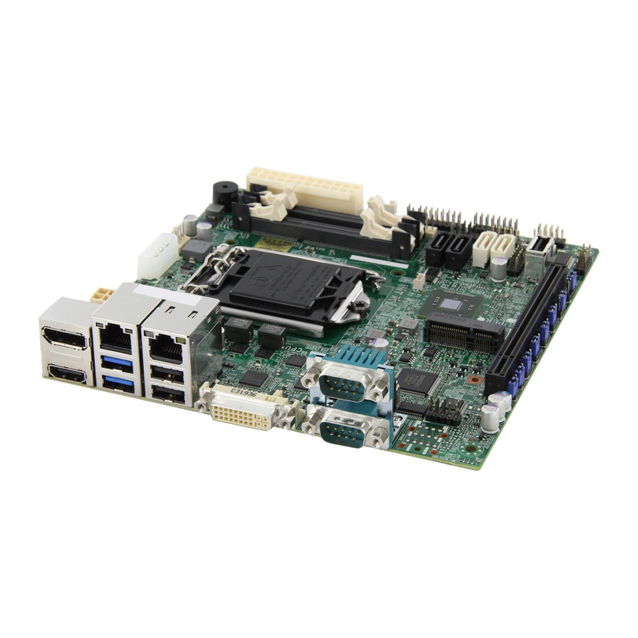
Page 14: X10Slv/-Q Image
X10SLV/-Q Motherboard User's Manual X10SLV/-Q Image Note: All graphics and images shown in this manual were based upon the latest PCB Revision available at the time of publishing of the manual. The motherboard you've received may or may not look exactly the same as the image shown in... -
Page 15: X10Slv/-Q Motherboard Layout
Chapter 1: Introduction X10SLV/-Q Motherboard Layout Important Notes to the User • Jumpers not indicated are for testing only. • See Chapter 2 for detailed information on jumpers, I/O ports and JF1 front panel connections. • " " indicates the location of "Pin 1". -
Page 16: X10Slv/-Q Quick Reference
X10SLV/-Q Motherboard User's Manual X10SLV/-Q Quick Reference Audio Ports (not drawn to scale) JWD1: WATCH JUSB2LAN2 1-2:RST JUSBLAN1 2-3:NMI HDMI LAN2 LAN1 USB2/3 USB0/1(3.0) BATTERY JPW2 JI2C2 JWD1 mini PCIE JBR1 JPAC1 X10SLV JPUSB1: JPME2 USB WAKE UP 1-2:ENABLE 2-3:DISABLE... -
Page 17: Ports, Leds, And Connectors
Chapter 1: Introduction Ports, LEDs, and Connectors Audio FP Front Panel Audio Header AUDIO Ports Audio Connectors on the I/O backpanel. Not available on the X10SLV-Q. Battery Onboard Battery COM1/COM2 COM1 and COM2 Ports (on the I/O backpanel*) COM3-COM5 COM3/COM4/COM5 Port Headers... -
Page 18: Motherboard Features
SO-DIMM 2 GB, 4 GB and 8GB Chipset X10SLV: Intel® H81 Express X10SLV-Q: Intel® Q87 Express Expansion Slots One (1) PCI-E x 16, Gen2 (Gen3 for X10SLV-Q only) Graphics Intel Integrated Graphics Independent Displays X10SLV: Two X10SLV-Q: Three Network Connections... - Page 19 Fan Control 3-pin Fan Headers Fan Speed Control System Management Watch Dog System resource alert via Supero Doctor III SuperoDoctor III Chassis Intrusion header and detection CD Utilities BIOS flash upgrade utility Drivers and software for Intel® H81 Express chipset utili-...
-
Page 20: X10Slv/-Q Motherboard Block Diagram
X10SLV/-Q Motherboard User's Manual X10SLV/-Q Motherboard Block Diagram X10SLV / X10SLV-Q BLOCK DIAGRAM RoHS 6/6 PCIe2.0_x16 PCIe3.0_x16 SVID VRM 12.5 VRD12.5 PCIe x16 SLOT 5.0GT/s 8.0GT/s (X10SLV) (X10SLV-Q) INTEL LGA1150 DDR3 (CHA) Digital port B DVI-I DIMMA1 DDI B (Socket-H3) -
Page 21: Chipset Overview
Chapter 1: Introduction Chipset Overview The X10SLV/-Q Motherboard supports a single 4th generation Intel® Core™ i7/ i5/i3 processor (LGA 1150). Built around the functionality and the capability of the Intel® H81 Express chipset (Q87 Express on the X10SLV-Q), the motherboard provides substantial system per- formance and storage capability for performance platforms in a compact package. -
Page 22: Pc Health Monitoring
The User can adjust the voltage thresholds to define the sensitivity of the voltage monitor by using SD III. Fan Status Monitor with Software The PC health monitor can check the RPM status of the cooling fans via Supero Doctor III. 1-10... -
Page 23: 1-4 Power Configuration Settings
Although most power supplies generally meet the specifications required by the CPU, some are inadequate. A 2-Amp of current supply on a 5V Standby rail is strongly recommended. Note: The X10SLV Motherboard series alternatively supports a 4-pin 12V DC in put power supply for embedded applications. 1-11... -
Page 24: Super I/O
X10SLV/-Q Motherboard User's Manual Super I/O The Super I/O provides five high-speed, 16550 compatible serial communication ports (UARTs). Each UART includes a 16-byte send/receive FIFO, a programmable baud rate generator, complete modem control capability and a processor interrupt system. Both UARTs provide legacy speed with baud rate of up to 115.2 Kbps as well as an advanced speed with baud rates of 250 K, 500 K, or 1 Mb/s, which sup- port higher speed modems. -
Page 25: Installation
Chapter 2: Installation Chapter 2 Installation Standardized Warning Statements The following statements are industry-standard warnings, provided to warn the user of situations which have the potential for bodily injury. Should you have questions or experience difficulty, contact Supermicro's Technical Support department for assis- tance. - Page 26 X10SLV/-Q Motherboard User's Manual Attention Danger d'explosion si la pile n'est pas remplacée correctement. Ne la remplacer que par une pile de type semblable ou équivalent, recommandée par le fabricant. Jeter les piles usagées conformément aux instructions du fabricant. ¡Advertencia! Existe peligro de explosión si la batería se reemplaza de manera incorrecta.
-
Page 27: Product Disposal
Chapter 2: Installation Product Disposal Warning! Ultimate disposal of this product should be handled according to all national laws and regulations. 製品の廃棄 この製品を廃棄処分する場合、 国の関係する全ての法律 ・ 条例に従い処理する必要が あります。 警告 本产品的废弃处理应根据所有国家的法律和规章进行。 警告 本產品的廢棄處理應根據所有國家的法律和規章進行。 Warnung Die Entsorgung dieses Produkts sollte gemäß allen Bestimmungen und Gesetzen des Landes erfolgen. -
Page 28: Static-Sensitive Devices
X10SLV/-Q Motherboard User's Manual القىانين واللىائح الىطنية جميع وفقا ل ينبغي التعامل معه هذا المنتج من التخلص النهائي عند 경고! 이 제품은 해당 국가의 관련 법규 및 규정에 따라 폐기되어야 합니다. Waarschuwing De uiteindelijke verwijdering van dit product dient te geschieden in overeenstemming met alle nationale wetten en reglementen. -
Page 29: Processor And Heatsink Installation
Chapter 2: Installation Processor and Heatsink Installation Warning: When handling the processor package, avoid placing direct pressure on the label area of the fan. Important: • Always connect the power cord last, and always remove it before adding, removing or changing any hardware components. Make sure that you install the processor into the CPU socket before you install the CPU heatsink. - Page 30 X10SLV/-Q Motherboard User's Manual 1. When the load plate is open, use your thumb and your index finger to hold the CPU at the north center edge and the south center edge of the CPU. North Center Edge South Center Edge 2.
- Page 31 Chapter 2: Installation 5. Once the CPU is properly installed, use your thumb to gently push the load plate handle down to the handle lock and lock it. CPU properly installed Load Plate Handle is locked into place 6. When the CPU is securely locked into the CPU socket, the plastic cap will be automatically loosened from the load plate.
-
Page 32: Installing An Active Cpu Heatsink With Fan
X10SLV/-Q Motherboard User's Manual Installing an Active CPU Heatsink with Fan 1. Locate the CPU Fan power connec- tor on the motherboard. (Refer to the layout on the right for the CPU Fan location.) 2. Position the heatsink so that the... - Page 33 Chapter 2: Installation 7. Align the four heatsink fasten- ers with the mounting holes on the motherboard. Gently push the pairs of diagonal fasteners (#1 & #2, and #3 & #4) into the mounting holes until you hear a click. Also, make sure to orient each fastener so that the narrow end of the groove is pointing...
-
Page 34: Removing The Heatsink
X10SLV/-Q Motherboard User's Manual Removing the Heatsink Warning: We do not recommend that the CPU or the heatsink be removed. However, if you do need to remove the heatsink, please follow the instructions below to remove the heatsink and to prevent damage done to the CPU or other components. -
Page 35: Tools Needed
Tools Needed Philips Screwdriver Stand Offs (4 pieces) Pan head screws (4 pieces) (Only if needed) Note: The above items are not provided with this motherboard. Location of Mounting Holes There are four (4) mounting holes on the X10SLV/-Q Motherboard. 2-11... -
Page 36: Installation Instructions
X10SLV/-Q Motherboard User's Manual Caution: To avoid damaging the motherboard and its components, please do not use a force greater than 8 lb/inch on each mounting screw during motherboard installation. Installation Instructions Install the I/O shield into the chassis. I/O Shield Locate the mounting holes on the motherboard. -
Page 37: System Memory
2. Insert each SO DIMM module vertically and snap it into place. Repeat step 1 to install DIMMB1 if needed. See instructions on the next page. Memory Support The X10SLV/-Q Motherboard supports up to 16GB of unbuffered DDR3 non-ECC SODIMMs (up to 1600 MHz in 2 SODIMM slots). Installing and Removing DIMMs... -
Page 38: The So Dimm Socket
X10SLV/-Q Motherboard User's Manual The SO DIMM Socket Position the SO DIMM module's bottom key so it aligns with the receptive point on the Align slot. Take note of the module's side notches and the locking clips on the socket. -
Page 39: Connectors/I/O Ports
9. DVI-I Port 3. Gb LAN1 Port 10. COM2 4. USB1 (3.0) 11. COM1 5. USB0 (3.0) 12. Audio Line In* 6. Gb LAN2 Port 13. Audio Line Out* 7. USB3 (2.0) 14. Audio Mic In* *X10SLV only Back Panel Connectors 2-15... -
Page 40: Universal Serial Bus (Usb)
X10SLV/-Q Motherboard User's Manual Universal Serial Bus (USB) Back Panel USB Type A USB 10 Pin Definitions Four Universal Serial Bus ports are locat- Pin# Definition Pin# Definition ed on the I/O backpanel. These are USB 0/1 (3.0) and USB 2/3 (2.0). Additionally, one header (USB 4/5, 2.0), and one Type... -
Page 41: Serial Ports (Com1~Com5)
Chapter 2: Installation Serial Ports (COM1~COM5) Serial Ports COM1~COM5 Pin Definitions Two COM ports (COM1, COM2) are Pin # Definition Pin # Definition located on the motherboard's I/O back panel. COM3, COM4 and COM5 are headers and are located near the I-SATA ports to provide additional onboard serial ports. -
Page 42: Vesa® Displayport™ (Displayport)
It can connect to virtually any display device using a DisplayPort adapter for devices such as VGA, DVI or HDMI. The X10SLV/-Q supports the DisplayPort standard version 1.2a. HDMI Port One HDMI (High-Definition Multimedia Interface) Port is located in the middle of the I/O backpanel. -
Page 43: Lan Ports (Lan1/Lan2)
Chapter 2: Installation LAN Ports (LAN1/LAN2) RJ45/LAN Pin Definitions Two gigabit LAN ports are located on the Pin # Definition Pin # Definition I/O back panel. These ports accept RJ45 TX_D1+ BI_D3- type cables and are used to connect the TX_D1- RX_D2- motherboard to a network. -
Page 44: Front Control Panel
X10SLV/-Q Motherboard User's Manual Front Control Panel JF1 contains header pins for various buttons and indicators that are normally lo- cated on a control panel at the front of the chassis. These connectors are designed specifically for use with Supermicro server chassis. See the figure below for the descriptions of the various control panel buttons and LED indicators. -
Page 45: Front Control Panel Pin Definitions
Chapter 2: Installation Front Control Panel Pin Definitions Power LED Power LED Pin Definitions (JF1) The Power LED connection is located on Pin# Definition pins 15 and 16 of JF1. Refer to the table +3.3V on the right for pin definitions. Ground HDD LED HDD LED... -
Page 46: Overheat (Oh)/Fan Fail Led
X10SLV/-Q Motherboard User's Manual Overheat (OH)/Fan Fail LED OH/Fan Fail Indicator Status Connect an LED Cable to the OH/Fan State Definition Fail connection on pins 7 and 8 of JF1 Normal to provide advanced warnings of chassis Overheat overheat or fan failure. Refer to the table... -
Page 47: Connecting Cables
Chapter 2: Installation Connecting Cables This section provides brief descriptions and pin-out definitions for onboard power connectors. Be sure to use the correct cable for each header or connector. 24-pin ATX Power Connector (JPW1) ATX Power 24-pin Connector The 24-pin power connector is used Pin Definitions (JPW1) to provide power to the motherboard. -
Page 48: Fan Headers
X10SLV/-Q Motherboard User's Manual Fan Headers The X10SLV/-Q Motherboard has three Fan Header fan headers (Fan1~Fan3). These fans Pin Definitions are 4-pin fan headers. Although Pins 1~3 Pin# Definition of the fan headers are backward compat- Ground ible with the traditional 3-pin fans, please... -
Page 49: Chassis Intrusion (Jl1)
Chapter 2: Installation Chassis Intrusion (JL1) Chassis Intrusion Pin Definitions (JL1) A Chassis Intrusion header is located Pin# Definition at JL1 on the motherboard. Attach the Intrusion Input appropriate cable from the chassis to Ground inform you of a chassis intrusion when the chassis has been opened. -
Page 50: Sata Dom Power (Jsd1)
X10SLV/-Q Motherboard User's Manual SATA DOM Power (JSD1) SATA DOM Power Pin Definitions The SATA DOM Power on JSD1 is used Pin# Definition to supply power to SATA Disk-on-Module (DOM) solid-state storage devices. Ground Ground System Management Bus (JSMB1 System Management... -
Page 51: Mini Pci-E Slot (Mini Pcie)
Chapter 2: Installation Mini PCI-E Slot (Mini PCIE) Mini PCI-E Pin Definitions The Mini PCI-E slot is used to install a Pin# Definition Pin# Definition compatible Mini PCI-E device. Refer to +3.3Vaux the table on right for pin definitions. The mSATA feature leverages the speed +1.5V and reliability of the SATA interface to provide a high performance, cost-effec-... -
Page 52: Front Panel Audio Control Header
X10SLV/-Q Motherboard User's Manual Front Panel Audio Control Header High Definition Fron Panel Audio When front panel headphones are plugged in, Pin# Signal the back panel audio output is disabled. This MC_L is done through the FP Audio header (AUDIO AUD_GND FP). -
Page 53: Speaker (Jd1)
Chapter 2: Installation Speaker (JD1) On the JD1 header, Pins 3-4 are used Speaker Connector Pin Definitions for the internal speaker. Close Pins 3-4 Pin Setting Definition with a cap to use the onboard speaker. Pins 3-4 Internal Speaker If you wish to use an external speaker, Pins 1-4 External Speaker attach the external speaker cable to Pins... -
Page 54: Jumper Settings
X10SLV/-Q Motherboard User's Manual Jumper Settings Explanation of Jumpers To modify the operation of the motherboard, jumpers can be used to choose between optional settings. Jumpers create shorts between two pins to change the function of the connector. Pin 1 is identified with a square solder pad on the printed circuit board. -
Page 55: Bios Recovery (Jbr1)
Chapter 2: Installation BIOS Recovery (JBR1) BIOS Recovery Jumper Settings Close pins 2 and 3 of Jumper JBR1 for BIOS Settings Definition recovery. The default setting is on pins 1 and 2 Pins 1-2 Normal (Default) for normal operation. See the table on the right Pins 2-3 Enabled for jumper settings. -
Page 56: Clear Cmos (Jbt1)
X10SLV/-Q Motherboard User's Manual Clear CMOS (JBT1) JBT1 is used to clear the CMOS. Instead of pins, this "jumper" consists of contact pads to prevent accidental clearing of CMOS. To activate, use a metal object such as a small screwdriver to touch both pads at the same Metal contact pads time, to short the connection. -
Page 57: Usb Wake-Up (Jpusb1)
Chapter 2: Installation USB Wake-Up (JPUSB1) USB Wake-Up Jumper Settings Use the JPUSB1 jumper to enable system Jumper Setting Definition "wake-up" via a USB device. This jumper Pins 1-2 Enabled allows you to "wake-up" the system by Pins 2-3 Disabled (Default) pressing a key on the USB keyboard or by clicking the USB mouse of your system. -
Page 58: Watch Dog Reset (Jwd1)
X10SLV/-Q Motherboard User's Manual Watch Dog Reset (JWD1) Watch Dog Jumper Settings Watch Dog (JWD1) is a system monitor that Jumper Setting Definition can reboot the system when a software ap- Pins 1-2 Reset plication hangs. Close pins 1~2 to reset the (default) system if an application hangs. -
Page 59: Onboard Indicators
Chapter 2: Installation Onboard Indicators GLAN Link/Speed LED Indicator LAN Port LEDs LED Color Definition Two LAN ports are located on the I/O No Connection or 10 Mbps Backpanel. Each Ethernet LAN port has Green (On) 100 Mbps Amber (On) 1 Gbps two LEDs. -
Page 60: 2-10 Serial Ata And Hdd Connections
SATA Connections (I-SATA0~I-SATA3) Four total Serial ATA (SATA) connectors are located on the motherboard. The X10SLV motherboard supports two SATA 3.0 (0/1) and two SATA 2.0 (2/3), while the X10SLV-Q supports four SATA 3.0 (0/1/2/3) connectors. These Serial Link connections provide faster data transmission than legacy Parallel ATA. See the table below for pin definitions. -
Page 61: Troubleshooting
Chapter 3: Troubleshooting Chapter 3 Troubleshooting Troubleshooting Procedures Use the following procedures to troubleshoot your system. If you have followed all of the procedures below and still need assistance, refer to the ‘Technical Support Procedures’ and/or ‘Returning Merchandise for Service’ section(s) in this chapter. Always disconnect the AC power cord before adding, changing or installing any hardware components. -
Page 62: Memory Errors
X10SLV/-Q Motherboard User's Manual 2. Use the speaker to determine if any beep codes exist. (Refer to Appendix A for details on beep codes.) 3. Remove all memory modules and turn on the system. (If the alarm is on, check the specs of memory modules, reset the memory or try a different one.) -
Page 63: Frequently Asked Questions
Frequently Asked Questions Question: What type of memory does my motherboard support? Answer: The X10SLV/-Q Motherboard supports up to 16GB of unbuffered non-ECC DDR3 (up to 1600 MHz), two-way interleaved or non-interleaved SODIMM memory. Question: Why does Microsoft Windows show less memory than what is... - Page 64 Notes: Always use the file named “ami.bat” to update the BIOS and insert a space between "ami.bat" and the filename. The BIOS-ROM-filename will bear the motherboard name (i.e., X10SLV) and build date as the extension. For example, "X10SLV0.526". When completed, your system will automatically reboot. If you choose the .exe file, please run the .exe file under Windows to create the BIOS flash floppy disk.
-
Page 65: Returning Merchandise For Service
Chapter 3: Troubleshooting Returning Merchandise for Service A receipt or copy of your invoice marked with the date of purchase is required before any warranty service will be rendered. You can obtain service by calling your vendor for a Returned Merchandise Authorization (RMA) number. When returning to the manufacturer, the RMA number should be prominently displayed on the outside of the shipping carton, and mailed prepaid or hand-carried. - Page 66 X10SLV/-Q Motherboard User's Manual Notes...
-
Page 67: Introduction
BIOS Introduction This chapter describes the AMI BIOS Setup Utility for the X10SLV/-Q. The ROM BIOS is stored in a Flash EEPROM and can be easily updated. This chapter de- scribes the basic navigation of the AMI BIOS Setup Utility setup screens. -
Page 68: How To Start The Setup Utility
X10SLV/-Q Motherboard User’s Manual How to Start the Setup Utility Normally, the only visible Power-On Self-Test (POST) routine is the memory test. As the memory is being tested, press the <Delete> key to enter the main menu of the AMI BIOS Setup Utility. From the main menu, you can access the other setup screens. -
Page 69: System Date/System Time
Day MM/DD/YYYY format. The time is entered in HH:MM:SS format. Note: The time is in the 24-hour format. For example, 5:30 P.M. appears as 17:30:00. The following BIOS items will also be displayed: Supermicro X10SLV/-Q Version Build Date Memory Information Total Memory This displays the total size of memory available in the system. -
Page 70: Advanced Setup Configurations
X10SLV/-Q Motherboard User’s Manual Advanced Setup Configurations Use the arrow keys to select Advanced Setup and press <Enter> to access the submenu items: Aptio Setup Utility - Copyright (C) 2012 American Megatrends, Inc. Main Boot Security Save & Exit Advanced System Boot Feature Setting ... -
Page 71: Wait For 'F1' If Error
Chapter 4: AMI BIOS Wait For 'F1' If Error Select Enabled to force the system to wait until the 'F1' key is pressed if an error occurs. The options are Disabled and Enabled. Interrupt 19 Capture Interrupt 19 is the software interrupt that handles the boot disk function. When this item is set to Enabled, the BIOS ROM of the host adaptors will "capture"... -
Page 72: Cpu Configuration
X10SLV/-Q Motherboard User’s Manual CPU Configuration The following CPU information will be displayed: • Type of CPU • CPU Signature • CPU Stepping • Microcode Patch • FSB Speed • Max (Maximum) CPU Speed • Min (Minimum) CPU Speed •... -
Page 73: Clock Spread Spectrum
Chapter 4: AMI BIOS Clock Spread Spectrum If this feature is set to Enabled, the BIOS will monitor the level of electromagnetic interference caused by the components and will attempt to reduce the interference whenever needed. The options are Enabled and Disabled. Hyper-threading Select Enabled to support Intel Hyper-threading Technology to enhance CPU per- formance. -
Page 74: Adjacent Cache Line Prefetch
X10SLV/-Q Motherboard User’s Manual Adjacent Cache Line Prefetch (Available when supported by the CPU) Select Enabled for the CPU to prefetch both cache lines for 128 bytes as comprised. Select Disabled for the CPU to prefetch both cache lines for 64 bytes. The options are Disabled and Enabled. - Page 75 Chapter 4: AMI BIOS Platform Power Limit Lock Use this feature to lock the power limit of the motherboard. The options are Enabled and Disabled. CPU Power Limit3 Use this feature to set the power limit for CPU3. Use the number keys on your keyboard to enter the value.
-
Page 76: Energy Performance
X10SLV/-Q Motherboard User’s Manual 2-Core Ratio Limit This increases (multiplies) 2 clock speeds in the CPU core in relation to the bus speed when two CPU cores are active. Press "+" or "-" on your keyboard to change the value. Enter 0 to use the manufacturer's default setting. -
Page 77: Package C-State Limit
Chapter 4: AMI BIOS CPU C6 Report (Available when "CPU C States" is set to Enabled) Select Enabled to allow the BIOS to report the CPU C6 State (ACPI C3) to the operating system. During the CPU C6 State, the power to all caches is turned off. -
Page 78: Acpi T State
X10SLV/-Q Motherboard User’s Manual ACPI T State Select Enabled to support Advanced Configuration and Power Interface (ACPI) Throttling States (T State), which will lower the power consumption level for the system as to the power consumption level set for CPU Performance State 1 to achieve power efficiency. -
Page 79: Primary Display
Use this item to select the graphics device installed in an expansion slot sup- ported by the CPU to be used as the primary display. The options are Auto, SLOT1 PCI-E 2.0 X16 or SLOT1 PCI-E 3.0 X16 (X10SLV-Q only). PCH Slot (Available when Primary Display is set to Auto) Use this item to select the graphics device installed in an expansion slot sup- ported by the PCH to be used as the primary display. -
Page 80: Gfx (Graphics) Low Power Mode
SLOT1 PCI-E 2.0 X16 (X10SLV only) SLOT1 PCI-E 3.0 X16 (X10SLV-Q only) SLOT1 PCI-E 2.0 X16- Gen X, option support up to Gen2 (X10SLV only) SLOT1 PCI-E 3.0 X16- Gen X, option support up to Gen3 (X10SLV-Q only) This feature allows the user to select PCI-E support for the device installed on Slot1. -
Page 81: Memory Configuration
Chapter 4: AMI BIOS PCH DMI Link ASPM Control Use this feature to set the ASPM (Active State Power Management) state on the device installed on the DMI Link supported by the PCH chip. The options are Disabled and Enabled. Memory Configuration ... -
Page 82: Pch-Io Configuration
X10SLV/-Q Motherboard User’s Manual Memory Scrambler This feature enables or disables memory scrambler support for memory error correction. The settings are Enabled and Disabled. PCH-IO Configuration This item displays the information for the PCH-IO Chip. • Intel PCH Rev ID •... -
Page 83: Ehci Hand-Off
SATA Mode Selection This item selects the mode for the installed SATA drives. The options are IDE, and AHCI. (RAID is an added option for the X10SLV-Q only) If the item above -SATA Mode Selection is set to AHCI, the following items... - Page 84 Software Preserve Support If the item above - SATA Mode Select is set to RAID, the following items are displayed (this is supported on the X10SLV-Q only): Serial ATA Port 0~ Port 3 This item displays the information detected on the installed SATA drives on the particular SATA port.
-
Page 85: Pcie/Pci/Pnp Configuration
The options are Disabled and Enabled. SLOT1 PCI-E 2.0 X16 OPROM (X10SLV only) SLOT1 PCI-E 3.0 X16 OPROM (X10SLV-Q only) Select Disabled to deactivate the selected slot, Legacy to activate the slot in legacy mode and EFI to activate the slot in EFI mode. -
Page 86: Onboard Lan1 Option Rom/Onboard Lan2 Option Rom
X10SLV/-Q Motherboard User’s Manual Onboard LAN1 Option ROM/Onboard LAN2 Option ROM Select PXE (Preboot Execution Environment) to boot the computer using a PXE device installed in a LAN port specified. Select Disabled to prevent system boot using a device installed in a LAN port. The options for Onboard LAN1 Option ROM are Disabled, and PXE.The options for Onboard LAN2 Option ROM are... -
Page 87: Trusted Computing
Chapter 4: AMI BIOS Trusted Computing (Available when a TPM Device is Detected) Configuration Security Device Support Select Enable for the AMI BIOS to automatically download the drivers needed to provide Trusted Computing platform support for this machine to ensure date integrity and network security. -
Page 88: Pch-Fw Configuration
X10SLV/-Q Motherboard User’s Manual PCH-FW Configuration The following information are displayed: • ME FW Version • ME Firmware Mode • ME Firmware Type • ME Firmware SKU • PTT Capability/State Firmware Update Configuration ME FW Image Re-Flash Select Enabled to re-flash the ME (Management Engine) Firmware. The options are Disabled and Enabled. -
Page 89: Transmit Mode (Serial Port 5)
Chapter 4: AMI BIOS (IO=3E8h; IRQ=3, 4, 5, 6, 7, 10, 11, 12) and (IO=2E8h; IRQ=3, 4, 5, 6, 7, 10, 11, 12). The options for Serial Port 3 are Auto, (IO=3E8h; IRQ=5), (IO=3E8h; IRQ=3, 4, 5, 6, 7, 10, 11, 12), (IO=2E8h; IRQ=3, 4, 5, 6, 7, 10, 11, 12), (IO=2E0h;... -
Page 90: Serial Port Console Redirection
X10SLV/-Q Motherboard User’s Manual • PCH Temperature • Fan 1 Speed ~ Fan 3 Speed • VCORE • • V_DIMM • 1.05V PCH • 3.3AVCC • 3.3VCC • 3.3VSB • VBAT Serial Port Console Redirection COM1~COM5 Use this feature to enable console redirection for COM1~COM5. The options are Enabled and Disabled. - Page 91 Chapter 4: AMI BIOS Redirection After BIOS POST: Always Enable, Bootloader Serial Port for Out-of-Band Management / Windows Emergency Management Services (EMS) Use this feature to enable console redirection. EMS Console Redirection Use this feature to enable console redirection for Serial Port Out-of-Band Manage- ment / Windows Emergency Management Services (EMS) ports.
-
Page 92: Boot Settings
X10SLV/-Q Motherboard User’s Manual Boot Settings Use this feature to configure Boot Settings: Aptio Setup Utility - Copyright (C) 2012 American Megatrends, Inc. Main Advanced Boot Security Save & Exit Sets the system boot order Set Boot Priority Boot Device... -
Page 93: Add New Boot Option
Chapter 4: AMI BIOS Add New Boot Option This feature allows the user to add a boot device from which the systems will boot after power-on. Add Boot Option Enter the name of the new boot option here. Path for Boot Option Enter the path of the new boot option here. -
Page 94: Security Settings
X10SLV/-Q Motherboard User’s Manual Security Settings This menu allows the user to configure the following security settings for the system. Aptio Setup Utility - Copyright (C) 2012 American Megatrends, Inc. Main Advanced Boot Security Save & Exit Password Description Set Administrator Password. -
Page 95: Save & Exit
Chapter 4: AMI BIOS Save & Exit Select the Exit tab from the BIOS Setup Utility screen to enter the Exit BIOS Setup screen. Aptio Setup Utility - Copyright (C) 2012 American Megatrends, Inc. Save & Exit Main Advanced Boot Security Exit system setup after saving Discard Changes and Exit... -
Page 96: Save As User Defaults
X10SLV/-Q Motherboard User’s Manual Save As User Defaults To set this feature, select Save as User Defaults from the Exit menu and press <En- ter>. This enables the user to save any changes to the BIOS setup for future use. -
Page 97: Post Error Beep Codes
Appendix A: POST Error Beep Codes Appendix A POST Error Beep Codes This section lists POST (Power On Self Test) error beep codes for the AMI BIOS. POST error beep codes are divided into two categories: recoverable and terminal. This section lists Beep Codes for recoverable POST errors. Recoverable POST Error Beep Codes When a recoverable type of error occurs during POST, BIOS will display a POST code that describes the problem. - Page 98 X10SLV/-Q Motherboard User's Manual Notes...
-
Page 99: Software Installation Instructions
X10SLV/-Q Motherboard User's Manual Appendix B Software Installation Instructions B-1 Installing Drivers Additional drivers and tools for your motherboard are available for download at the Supermicro website. To install these software programs and drivers, run the application and a screen will appear as below. Click the icons to the right of these items. -
Page 100: Configuring Supero Doctor Iii
The Supero Doctor III program is a Web-base management tool that supports remote management capability. It includes Remote and Local Management tools. The local management is called the SD III Client. The Supero Doctor III program included on the CDROM that came with your motherboard allows you to monitor the environment and operations of your system. - Page 101 X10SLV/-Q Motherboard User's Manual Supero Doctor III Interface Display Screen-II (Remote Control) Note: SD III Software Revision 1.0 can be downloaded from our Web site at: ftp://ftp.supermicro.com/utility/Supero_Doctor_III/. You can also download SDIII User's Guide at: http://www.supermicro.com/PRODUCT/ Manuals/SDIII/UserGuide.pdf. For Linux, we will still recommend that you...
- Page 102 X10SLV/-Q Motherboard User's Manual Notes...
-
Page 103: Uefi Bios Recovery Instructions
Appendix C: UEFI BIOS Recovery Appendix C UEFI BIOS Recovery Instructions Warning! Do not upgrade the BIOS unless your system has a BIOS-related issue. Flashing the wrong BIOS can cause irreparable damage to the system. In no event shall Supermicro be liable for direct, indirect, special, incidental, or consequential damages arising from a BIOS update. - Page 104 X10SLV/-Q Motherboard User’s Manual To perform UEFI BIOS recovery using a USB-attached device, follow the instruc- tions below. 1. Using a different machine, copy the "Super.ROM" binary image file into the disc Root "\" Directory of a USB device or a writeable CD/DVD.
- Page 105 Appendix C: UEFI BIOS Recovery 5. When the screen as shown above displays, using the arrow key, select the item- "Proceed with flash update" and press the <Enter> key. You will see the progress of BIOS Recovery as shown in the screen below. Note: Do not interrupt the process of BIOS flashing until it is com- pleted.
- Page 106 X10SLV/-Q Motherboard User’s Manual 8. When a DOS prompt appears, enter AMI.BAT BIOSname.### at the prompt. Note: Do not interrupt this process until BIOS flashing is completed. 9. After seeing the message that BIOS update is completed, unplug the AC pow- er cable from the power supply to clear CMOS, and then plug the AC power cable in the power supply again to power on the system.
- Page 107 Disclaimer The products sold by Supermicro are not intended for and will not be used in life support systems, medical equipment, nuclear facilities or systems, aircraft, aircraft devices, aircraft/emergency communication devices or other critical systems whose failure to perform be reasonably expected to result in significant injury or loss of life or catastrophic property damage.
Need help?
Do you have a question about the X10SLV and is the answer not in the manual?
Questions and answers