Table of Contents
Advertisement
Quick Links
Advertisement
Table of Contents

Related Manuals for Supero X10SRA


Summary of Contents for Supero X10SRA
- Page 1 X10SRA X10SRA-F USER’S MANUAL Revision 1.1b...
- Page 2 The information in this User’s Manual has been carefully reviewed and is believed to be accurate. The vendor assumes no responsibility for any inaccuracies that may be contained in this document, makes no commitment to update or to keep current the information in this manual, or to notify any person or organization of the updates.
-
Page 3: Manual Organization
This manual is written for system integrators, PC technicians and knowledgeable PC users. It provides information for the installation and use of the X10SRA/X10SRA-F motherboard. Manual Organization Chapter 1 describes the features, specifications and performance of the motherboard, and provides detailed information on the Intel C612 Express chipset. -
Page 4: Checklist
Supermicro X10SRA/X10SRA-F Motherboard User’s Manual Checklist Congratulations on purchasing your computer motherboard from an ac- knowledged leader in the industry. Supermicro boards are designed with the utmost attention to detail to provide you with the highest standards in quality and performance. -
Page 5: Standardized Warning Statements
Standardized Warning Statements Standardized Warning Statements The following statements are industry-standard warnings, provided to warn the user of situations which have the potential for bodily injury. Should you have questions or experience difficulty, contact Supermicro's Technical Support department for assistance. Only certified technicians should attempt to install or configure components. -
Page 6: Product Disposal
Supermicro X10SRA/X10SRA-F Motherboard User’s Manual ¡Advertencia! Existe peligro de explosión si la batería se reemplaza de manera incor- recta. Reemplazar la batería exclusivamente con el mismo tipo o el equivalente recomendado por el fabricante. Desechar las baterías gasta- das según las instrucciones del fabricante. - Page 7 Standardized Warning Statements 製品の廃棄 この製品を廃棄処分する場合、 国の関係する全ての法律 ・ 条例に従い処理する必要が あり ます。 警告 本产品的废弃处理应根据所有国家的法律和规章进行。 警告 本產品的廢棄處理應根據所有國家的法律和規章進行。 Warnung Die Entsorgung dieses Produkts sollte gemäß allen Bestimmungen und Gesetzen des Landes erfolgen. ¡Advertencia! Al deshacerse por completo de este producto debe seguir todas las leyes y reglamentos nacionales.
-
Page 8: Contacting Supermicro
Supermicro X10SRA/X10SRA-F Motherboard User’s Manual Contacting Supermicro Headquarters Address: Super Micro Computer, Inc. 980 Rock Ave. San Jose, CA 95131 U.S.A. Tel: +1 (408) 503-8000 Fax: +1 (408) 503-8008 Email: marketing@supermicro.com (General Information) support@supermicro.com (Technical Support) www.supermicro.com Site: Europe Address: Super Micro Computer B.V. -
Page 9: Where To Find More Information
Contacting Supermicro Where to Find More Information For your system to work properly, please follow the links below to download all necessary drivers/utilities and the user's manual for your motherboard. SMCI product manuals: http://www.supermicro.com/support/manuals/ Product Drivers and utilities: ftp://ftp.supermicro.com/ If you have any questions, please contact our support team at support@ supermicro.com. -
Page 10: Table Of Contents
Supermicro X10SRA/X10SRA-F Motherboard User’s Manual Table of Contents Preface Manual Organization ................iii Checklist ..................iv Conventions Used in the Manual ............iv Standardized Warning Statements ............v Battery Handling ............... v Product Disposal ...............vi Contacting Supermicro ..............viii Where to Find More Information............ix... - Page 11 Ethernet Ports ..............2-17 Back Panel High Definition Audio (HD Audio) ...... 2-17 PS/2 Keyboard/Mouse Port ..........2-18 VGA Port (X10SRA-F only) ..........2-18 Front Control Panel .............. 2-19 Front Control Panel Pin Definitions ......... 2-20 Power LED ..............2-20 HDD LED ................
- Page 12 Supermicro X10SRA/X10SRA-F Motherboard User’s Manual Jumper Settings ..............2-28 Explanation of Jumpers ............2-28 LAN1/LAN2 Enable/Disable ..........2-28 Clear CMOS (JBT1, CLR_CMOS_SW, S8) ......2-29 PCI Slot SMB Enable (I C1/I C2) ........2-29 Audio Enable (JPAC1) ............2-30 Watch Dog Enable/Disable ..........2-30 USB Wake-Up (JPUSB1) ............
- Page 13 Table of Contents Chapter 4 BIOS Introduction ................4-1 Starting BIOS GUI Setup Utility ..........4-1 How To Change the Configuration Data ........4-2 How to Start the Setup Utility ..........4-2 Saving and Loading..............4-3 Save and Load ..............4-3 Restore Defaults ..............
- Page 14 Supermicro X10SRA/X10SRA-F Motherboard User’s Manual Turbo Mode ..............4-10 P-STATE Coordination ............4-11 Chipset ................4-12 System Agent..............4-12 Intel VT for Directed I/O (VT-d) ......... 4-13 PCH I/O ................4-14 Azalia (HD Audio) ............4-14 On Board Chip ..............4-15 Memory ................
- Page 15 CPU SLOT4 PCI-E 3.0 X8 (IN X16) OPROM, PCH SLOT5 PCI-E 2.0 X1 (IN X4) OPROM, CPU SLOT6 PCI-E 3.0 X16 OPROM ........4-37 Video Option ROM Type (X10SRA-F) ........4-37 Onboard LAN Option ROM Type .......... 4-37 Onboard LAN1 Option ROM/Onboard LAN2 Option ROM ..4-37 Network Stack ..............
- Page 16 Supermicro X10SRA/X10SRA-F Motherboard User’s Manual Super IO Configuration ............4-40 Serial Port 1 Configuration ..........4-40 Current Config (IRQ) ............4-40 Change (IRQ) Settings ............4-41 4-11 Security ................4-41 Password ................4-41 Administrator Password ............. 4-42 User Password ..............4-42 User Password ..............
- Page 17 Table of Contents UEFI Application BBS Priorities ........... 4-48 BIOS Features ..............4-48 Bootup Numlock State ............4-48 AddOn ROM Display Mode ..........4-48 Wait for "F1" for Error ............4-49 Interrupt 19 Capture ............4-49 Retry Boot ..............4-49 Watch Dog Function ............
- Page 18 Supermicro X10SRA/X10SRA-F Motherboard User’s Manual Notes xviii...
-
Page 19: Introduction
The X10SRA/X10SRA-F Motherboard supports a single Intel® E5-26xx series , E5-16xx series or Core™ i7 processor, in an LGA 2011-3 socket. With the Intel® C612 chipset built in, the X10SRA/X10SRA-F mother- board offers substantial system performance and storage capability for workstation/server platforms. -
Page 20: Motherboard Features
Eight (8) USB 3.0 ports: Six (6) ports on the rear I/O panel and Two (2) ports on one header Keyboard/Mouse One shared PS/2 Keyboard/Mouse port on the I/O rear I/O panel Other I/O Ports One (1) VGA Port (X10SRA-F only) One (1) Serial Port header (COM1) - Page 21 System Management PECI (Platform Environment Configuration Inter- face) 2.0 support System resource alert via SuperDoctor ® III SuperDoctor III, Watch Dog, NMI IPMI (for X10SRA-F only) Chassis Intrusion header and detection BIOS flash upgrade utility CD Utilities Drivers and software for Intel® C612 Express...
-
Page 22: Special Features
Supermicro X10SRA/X10SRA-F Motherboard User’s Manual 1-4 Special Features Recovery from AC Power Loss Basic I/O System (BIOS) provides a setting for you to determine how the system will respond when AC power is lost and then restored to the system. You can choose for the system to remain powered off, (in which case you must press the power switch to turn it back on), or for it to automatically return to a power-on state. -
Page 23: System Resource Alert
Chapter 1: Introduction System Resource Alert This feature is available when the system is used with SuperDoctor III in the Windows OS environment or used with SuperDoctor II in Linux. SuperDoctor is used to notify the user of certain system events. For example, you can also configure SuperDoctor to provide you with warnings when the system temperature, CPU temperatures, voltages and fan speeds go beyond predefined thresholds. -
Page 24: Power Supply
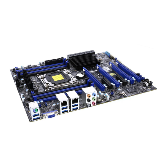
Supermicro X10SRA/X10SRA-F Motherboard User’s Manual 1-7 Power Supply As with all computer products, a stable power source is necessary for proper and reliable operation. It is even more important for processors that have high CPU clock rates. This motherboard accommodates 24-pin ATX power supplies. Although most power supplies generally meet the specifications required by the CPU, some are inadequate. - Page 25 Chapter 1: Introduction X10SRA/X10SRA-F Motherboard Image Note: All graphics shown in this manual were based upon the latest PCB Revision available at the time of publishing of the manual. The motherboard you've received may or may not look exactly the same...
- Page 26 Supermicro X10SRA/X10SRA-F Motherboard User’s Manual X10SRA/X10SRA-F Motherboard Layout JUSB30_I2 Important Notes to the User • See Chapter 2 for detailed information on jumpers, I/O ports and JF1 front panel connections. • " " indicates the location of "Pin 1". •...
- Page 27 Pins 1-2 (Enabled) JPB1 BMC Enable/Disable ( Pins 1-2 (Enabled) X10SRA-F only) JPG1 Onboard VGA Enable ( Pins 1-2 (Enabled) X10SRA-F only) For the X10SRA-F, reboot time may be longer after clearing CMOS. This is due to the additional IPMI functions.
-
Page 28: Connector Description
Supermicro X10SRA/X10SRA-F Motherboard User’s Manual Connector Description I/O Back Panel See Back Panel I/O Connectors, below right Audio FP Front Panel Audio Header Onboard Battery Fan 1,2,3,4,5 System/CPU Fan Headers (Fan1: CPU Fan) Speaker/buzzer (Pins 1~4: External Speaker, Pins 3~4: Buzzer) -
Page 29: System Block Diagram
Chapter 1: Introduction X10SRA/X10SRA-F Block Diagram VR12.5 #0-8 #0-4 8 PHASE #0-7 #0-3 145W #0-6 #0-2 #0-5 #0-1 VR12.5 VR12.5 2 PHASE 2 PHASE LGA2011-3 PCI-E X16 Gen3 PCI-E X16 or X8 Gen3 JPCIE6 JPCIE4 PCI-E X8 Gen3 PCI-E JPCIE1... - Page 30 Supermicro X10SRA/X10SRA-F Motherboard User’s Manual Notes 1-12...
-
Page 31: Installation
Chapter 2: Installation Chapter 2 Installation 2-1 Installation Components and Tools Needed Screws Phillips-Head Screwdriver Processor DDR4 DIMMs PC Chassis Heatsink with Fan Power Supply Video Card (Optional) SATA/USB Optical Drive (Optional) SATA Hard Disk Drive... -
Page 32: Static-Sensitive Devices
Supermicro X10SRA/X10SRA-F Motherboard User’s Manual 2-2 Static-Sensitive Devices Electrostatic-Discharge (ESD) can damage electronic com ponents. To avoid damaging your system board, it is important to handle it very carefully. The following measures are generally sufficient to protect your equipment from ESD. -
Page 33: Processor And Heatsink Installation
Chapter 2: Installation 2-3 Processor and Heatsink Installation Attention! When handling the processor package, avoid placing direct pressure on the label area of the fan. Important: Always connect the power cord last, and always remove it before adding, removing or changing any hardware components. Make sure that you install the processor into the CPU socket before you install the CPU heatsink. - Page 34 Supermicro X10SRA/X10SRA-F Motherboard User’s Manual 1. There are two load levers on the LGA2011-3 socket. To open the socket cover, first press and release the load lever labeled 'Open 1st'. Press down on Load Lever labeled 'Open 1st'. 2. Press the second load lever labeled 'Close 1st' to release the load plate that covers the CPU socket from its locking position.
- Page 35 Chapter 2: Installation 4. Use your thumb and index finger to hold the CPU on its edges. Align the CPU keys, which are semi-circle cutouts, against the socket keys. Socket Keys CPU Keys 5. Once they are aligned, carefully lower the CPU straight down into the socket.
- Page 36 Supermicro X10SRA/X10SRA-F Motherboard User’s Manual 7. Close the load plate with the CPU inside the socket. Lock the 'Close 1st' lever first, then lock the 'Open 1st' lever second. Use your thumb to gently push the load levers down to the lever locks.
-
Page 37: Installing A Cpu Heatsink
Chapter 2: Installation Installing a CPU Heatsink 1. Apply the proper amount of thermal grease to the heatsink. 2. Place the heatsink on top of the CPU so that the two mount- ing holes on the heatsink are aligned with those on the retention mechanism. -
Page 38: Removing A Heatsink
Supermicro X10SRA/X10SRA-F Motherboard User’s Manual Removing a Heatsink Warning: We do not recommend that the CPU or the heatsink be removed. However, if you do need to remove the heatsink, please follow the instruc- tions below to uninstall the heatsink to avoid damaging the CPU or other components. -
Page 39: Installing Ddr4 Memory
DIMMA1 DIMMA2 next page for the location). For DIMMB1 DIMMB2 the system to work properly, please use the memory modules IPMI CODE X10SRA/ JPW2 MAC CODE X10SRA-F BAR CODE of the same type and speed in MH11 the same motherboard. -
Page 40: Memory Population Guidelines
Supermicro X10SRA/X10SRA-F Motherboard User’s Manual Memory Support The X10SRA (-F) supports up to 512GB of ECC LRDIMM, up to 2400MHz, or 256GB ECC RDIMM, up to 2400MHz, or up to 64GB ECC/Non-ECC Unbuffered UDIMM (for Core i7 only), up to 2400MHz, in 8 memory slots. - Page 41 Chapter 2: Installation Notes Be sure to use memory modules of the same type, same speed, same frequency on the same motherboard. Mixing of memory modules of different types and speeds is not allowed. Due to memory allocation to system devices, the amount of memory that remains available for operational use will be re- duced when 4 GB of RAM is used.
- Page 42 Supermicro X10SRA/X10SRA-F Motherboard User’s Manual Populating RDIMM/LRDIMM DDR4 Memory Modules for the E5-2600v3-based Motherboard Speed (MT/s); Voltage (V); Slot Per Channel (SPC) and DIMM Per Channel (DPC) DIMM Capacity Ranks Per (GB) DIMM and Type 1 Slot Per Data 2 Slots Per Channel...
-
Page 43: Motherboard Installation
FAN5 JBR1 JPUSB1 1-2 ENABLE SW_BIOSRC 2-3 DISABLE JPL2 FAN4 1-2 ENABLE 2-3 DISABLE DIMMA1 DIMMA2 DIMMB1 DIMMB2 IPMI CODE X10SRA/ JPW2 MAC CODE X10SRA-F BAR CODE MH11 DIMMD2 CHASSIS INTRUSION DIMMD1 JBT1 LED4 DIMMC2 DIMMC1 JSD1 :SATA DOM POWER... -
Page 44: Installing The Motherboard
Supermicro X10SRA/X10SRA-F Motherboard User’s Manual Installing the Motherboard 1. Install the I/O shield into the back of the chassis. 2. Locate the mounting holes on the motherboard. (See the previous page.) 3. Locate the matching mounting holes on the chassis. Align the mounting holes on the motherboard against the mounting holes on the chassis. -
Page 45: Connectors/Io Ports
N. S/PDIF Out D. VGA Port* K. Clear CMOS O. Line In E. Gb LAN Port 1 (shared IPMI*) P. Line Out F. USB 3.0 Port 10 Q. Mic In G. USB 3.0 Port 11 X10SRA-F only X10SRA-F only HD Audio 2-15... -
Page 46: Universal Serial Bus (Usb)
Supermicro X10SRA/X10SRA-F Motherboard User’s Manual Universal Serial Bus (USB) Six USB 3.0 ports (10/11, 12/13, 14/15) are located on the I/O back panel. In addition, one USB 3.0 header (USB 16/17) is also located on the motherboard to provide front chassis access using USB cables (not included). -
Page 47: Ethernet Ports
Chapter 2: Installation Ethernet Ports LAN Ports Pin Definition Two Gigabit Ethernet ports (LAN1/LAN2) Pin# Desc Pin# Desc are located next to the HD Audio Con- VBUS1 TD0- nector on the I/O Backpanel to provide TD1+ network connections. These ports accept TD1- RJ45 type cables. -
Page 48: Ps/2 Keyboard/Mouse Port
Supermicro X10SRA/X10SRA-F Motherboard User’s Manual PS/2 Keyboard/Mouse Port A combination PS/2 Keyboard/Mouse port is supported on the back panel. This may be used with either a PS/2 keyboard or PS/2 mouse, or both when using a 'Y' PS/2 cable. VGA Port (X10SRA-F only) A VGA port is located next to the USB ports 0/1 on the I/O backpanel. -
Page 49: Front Control Panel
Chapter 2: Installation Front Control Panel JF1 contains header pins for various buttons and indicators that are normally located on a control panel at the front of the chassis. These connectors are designed specifically for use with Supermicro chassis. See the figure below for the descriptions of the front control panel buttons and LED indicators. -
Page 50: Front Control Panel Pin Definitions
Supermicro X10SRA/X10SRA-F Motherboard User’s Manual Front Control Panel Pin Definitions Power LED Power LED Pin Definitions (JF1) The Power LED connection is located on Pin# Definition pins 15 and 16 of JF1. Refer to the table +3.3V on the right for pin definitions. -
Page 51: Nmi Button
Chapter 2: Installation NMI Button Pin Definitions (JF1) The non-maskable interrupt button- Pin# Definition header is located on pins 19 and 20 of JF1. Refer to the table on the rightfor Ground pin definitions. Power Fail LED Power Fail Pin Definitions (JF1) Pin# Definition Connect an LED cable to the Power Fail... -
Page 52: Connecting Cables
Supermicro X10SRA/X10SRA-F Motherboard User’s Manual 2-7 Connecting Cables This section provides brief descriptions and pin-out definitions for on- board headers and connectors. Be sure to use the correct cable for each header or connector. ATX Power 24-pin Connector ATX Main PWR & CPU PWR Pin Definitions (JPW1) Connectors (JPW1 &... -
Page 53: Fan Headers (Fan 1 ~ Fan 5)
Chapter 2: Installation Fan Headers (Fan 1 ~ Fan 5) Fan Header Pin Definitions The X10SRA/X10SRA-F has five fan head- Pin# Definition ers (Fan 1~Fan 5). These fans are 4-pin Ground (Black) fan headers. Although pins 1-3 of the fan 2.5A/+12V... -
Page 54: Internal Buzzer (Sp1)
Supermicro X10SRA/X10SRA-F Motherboard User’s Manual Internal Buzzer (SP1) Internal Buzzer Pin Definition The Internal Buzzer (SP1) can be used Pin# Definitions to provide audible indications for various Pin 1 Pos. (+) Beep In beep codes. See the table on the right Pin 2 Neg. -
Page 55: Dom Pwr Connector (Jsd1)
IPMI slot is located at IPMB. Connect the Pin# Definition appropriate cable here to use the IPMB Clock I2C connection on your system. Sup- Ground ported on the X10SRA-F only. Data A. DOM Power No Connection B STBY PWR C System Management Bus AUDIO_FP... -
Page 56: Tpm Header (Jtpm1)
Supermicro X10SRA/X10SRA-F Motherboard User’s Manual TPM Header (JTPM1) Trusted Platform Module Header Pin Definitions This header is used to connect a Pin # Definition Pin # Definition Trusted Platform Module (TPM), LCLK which is available from a third- LFRAME No Pin party vendor. -
Page 57: Front Panel Audio Header (Audio Fp)
FAN5 JBR1 JPUSB1 1-2 ENABLE 2-3 DISABLE SW_BIOSRC JPL2 FAN4 1-2 ENABLE 2-3 DISABLE DIMMA1 DIMMA2 DIMMB1 DIMMB2 IPMI CODE X10SRA/ JPW2 MAC CODE X10SRA-F BAR CODE MH11 DIMMD2 CHASSIS INTRUSION DIMMD1 JBT1 LED4 DIMMC2 DIMMC1 JSD1 :SATA DOM POWER... -
Page 58: Jumper Settings
Supermicro X10SRA/X10SRA-F Motherboard User’s Manual 2-8 Jumper Settings Explanation of Jumpers To modify the operation of the mother- board, jumpers can be used to choose between optional settings. Jumpers create shorts between two pins to change the function of the connector. -
Page 59: Pci Slot Smb Enable
FAN5 JBR1 JPUSB1 1-2 ENABLE 2-3 DISABLE SW_BIOSRC JPL2 FAN4 1-2 ENABLE 2-3 DISABLE DIMMA1 DIMMA2 DIMMB1 DIMMB2 IPMI CODE X10SRA/ JPW2 MAC CODE X10SRA-F BAR CODE MH11 DIMMD2 CHASSIS INTRUSION DIMMD1 JBT1 LED4 DIMMC2 DIMMC1 JSD1 :SATA DOM POWER... -
Page 60: Audio Enable (Jpac1)
Supermicro X10SRA/X10SRA-F Motherboard User’s Manual Audio Enable (JPAC1) Audio Enable/Disable Jumper Settings JPAC1 allows you to enable or disable the Both Jumpers Definition onboard audio support. The default posi- Pins 1-2 Enabled tion is on pins 1 and 2 to enable onboard... -
Page 61: Usb Wake-Up (Jpusb1)
FAN5 JBR1 JPUSB1 1-2 ENABLE SW_BIOSRC 2-3 DISABLE JPL2 FAN4 1-2 ENABLE 2-3 DISABLE DIMMA1 DIMMA2 DIMMB1 DIMMB2 IPMI CODE X10SRA/ JPW2 MAC CODE X10SRA-F BAR CODE MH11 DIMMD2 CHASSIS INTRUSION DIMMD1 JBT1 LED4 DIMMC2 DIMMC1 JSD1 :SATA DOM POWER... -
Page 62: Manufacturing Mode (Jpme2)
See Normal (Default) the table on the right for jumper set- VGA Disabled tings. Supported on the X10SRA-F only. BMC Enable/Disable (JPB1) A. Manufacturing Mode Close Pin 2 and Pin 3 of jumper JPB1 to B. -
Page 63: Bios Recovery Switch (Jbr1)
FAN5 JBR1 JPUSB1 1-2 ENABLE 2-3 DISABLE SW_BIOSRC JPL2 FAN4 1-2 ENABLE 2-3 DISABLE DIMMA1 DIMMA2 DIMMB1 DIMMB2 IPMI CODE X10SRA/ JPW2 MAC CODE X10SRA-F BAR CODE MH11 DIMMD2 CHASSIS INTRUSION DIMMD1 JBT1 LED4 DIMMC2 DIMMC1 JSD1 :SATA DOM POWER... -
Page 64: Onboard Indicators
On, blink- BMC running normal board Baseboard Management Controller (BMC). See the table on the right for Note: this status display definitions. feature is for the X10SRA-F only. A. LAN 1/2 LEDs B. BMC Heartbeat AUDIO_FP LAN2 LAN1 USB 14/15(3.0) USB 12/13(3.0) -
Page 65: Power Led (Le2)
FAN5 JBR1 JPUSB1 1-2 ENABLE SW_BIOSRC 2-3 DISABLE JPL2 FAN4 1-2 ENABLE 2-3 DISABLE DIMMA1 DIMMA2 DIMMB1 DIMMB2 IPMI CODE X10SRA/ JPW2 MAC CODE X10SRA-F BAR CODE MH11 DIMMD2 CHASSIS INTRUSION DIMMD1 JBT1 DIMMC2 LED4 DIMMC1 JSD1 :SATA DOM POWER... -
Page 66: Sata Connections
Supermicro X10SRA/X10SRA-F Motherboard User’s Manual 2-10 SATA Connections SATA Connections (I-SATA0~5, S-SATA0~3) Ten Serial ATA (SATA) 3.0 connectors (I-SATA0~5, S-SATA0~3) are sup- ported on the board. All SATA 3.0 ports are supported by the Intel C612 PCH chip. RAID 0,1,5,10 are supported on all SATA ports. These high speed ports support transfer rates of up to 6Gb/s. -
Page 67: Troubleshooting
Chapter 3: Troubleshooting Chapter 3 Troubleshooting 3-1 Troubleshooting Procedures Use the following procedures to troubleshoot your system. If you have followed all of the procedures below and still need assistance, refer to the ‘Technical Support Procedures’ and/or ‘Returning Merchandise for Service’ section(s) in this chapter. -
Page 68: No Video
Supermicro X10SRA/X10SRA-F Motherboard User’s Manual No Video 1. If the power is on, but you have no video--in this case, you will need to re- move all the add-on cards and cables first. 2. Use the speaker to determine if any beep codes exist. (Refer to Appendix A for details on beep codes.) -
Page 69: Technical Support Procedures
Chapter 3: Troubleshooting 3-2 Technical Support Procedures Before contacting Technical Support, please make sure that you have followed all the steps listed below. Also, Note that as a motherboard manufacturer, Supermicro does not sell directly to end users, so it is best to first check with your distributor or reseller for troubleshooting services. -
Page 70: Frequently Asked Questions
Supermicro X10SRA/X10SRA-F Motherboard User’s Manual 3-3 Frequently Asked Questions Question: What type of memory does my motherboard support? Answer: The X10SRA/-F supports up to 512GB of DDR4 memory. See Section 2-4 for details. Question: How do I update my BIOS? Answer: We do NOT recommend that you upgrade your BIOS if you are not experiencing any problems with your system. -
Page 71: Battery Removal And Installation
Chapter 3: Troubleshooting Important: The SPI BIOS chip installed on this motherboard is not removable. To repair or replace a damaged BIOS chip, please send your motherboard to RMA at Supermicro for service. Question: I think my BIOS is corrupted. How can I recover my BIOS? Answer: Please see Appendix C-BIOS Recovery for detailed instructions. -
Page 72: Returning Motherboard For Service
Supermicro X10SRA/X10SRA-F Motherboard User’s Manual Battery Installation 1. To install an onboard battery, follow the steps 1& 2 above and con- tinue below: 2. Identify the battery's polarity. The positive (+) side should be fac- ing up. 3. Insert the battery into the battery holder and push it down until you hear a click to ensure that the battery is securely locked. -
Page 73: Introduction
4-1 Introduction This chapter describes the AMI BIOS Setup Utility for the X10SRA/ X10SRA-F motherboard. The ROM BIOS is stored in a Flash EEPROM and can be easily updated. This chapter describes the basic navigation of the AMI BIOS Setup Utility setup screens. -
Page 74: How To Change The Configuration Data
Supermicro X10SRA/X10SRA-F Motherboard User’s Manual The AMI BIOS GUI Setup Utility uses a mouse pointer navigation system similar to standard graphical user interfaces. Hover and click an icon to select a section, click a down arrow to select from an options list. -
Page 75: Saving And Loading
Chapter 4: AMI BIOS enter the main menu of the AMI BIOS GUI Setup Utility. From the Setup Home screen, you can access the other Setup Sections. 4-2 Saving and Loading Save and Load The Save and Load icon brings up a pop-up menu that enables the user to choose from different saving options at the end of the session:... -
Page 76: Restore Defaults
Supermicro X10SRA/X10SRA-F Motherboard User’s Manual Restore Defaults To set this feature, select Restore Defaults from the Save & Load menu and click <OK>. These are factory settings designed for maximum sys- tem stability. Save All Settings Only When you have completed the system configuration changes, select this option to save all changes made. - Page 77 Chapter 4: AMI BIOS The Booting icon brings up a pop-up menu that enables the user to choose the booting mode, location and order of priority: See Section 4-12 (Booting) for more information.
-
Page 78: System Information
The System Information Screen displays the motherboard's configuration. Motherboard The following information are displayed in this section: • Motherboard Model Name - X10SRA (-F). • BIOS Version - this item displays the BIOS version number. • Build Date - displays the BIOS build date. -
Page 79: Processor (Cpu)
Chapter 4: AMI BIOS 4-4 Processor (CPU) Information The following information are be displayed in this section: • Type and Speed of CPU - indicates the brand, model name, model number of the CPU and it's rated clock speed. • CPU Signature - displays the unique signature embedded in the CPU. -
Page 80: Performance
Supermicro X10SRA/X10SRA-F Motherboard User’s Manual Performance Hyper-threading [ALL] Select Enabled to support Intel Hyper-threading Technology to enhance CPU performance. The options are Enabled and Disabled. Execute-Disable Bit Capability (Available if supported by the OS & the CPU) Select Enabled to enable the Execute-Disable Bit which will allow the... -
Page 81: Enable Smx
Chapter 4: AMI BIOS Enable SMX Select Enable to activate SMX speed technology. The options are Enabled and Disabled. PPIN Control Select Enable to unlock the PPIN control. The options are Enabled and Disabled. Hardware Prefetcher (Available when supported by the CPU) If set to Enabled, the hardware prefetcher will prefetch streams of data and instructions from the main memory to the L2 cache to improve CPU performance. -
Page 82: Power Management
Supermicro X10SRA/X10SRA-F Motherboard User’s Manual Power Management Power Technology Select Energy Efficiency to support power-saving mode. Select Custom to customize system power settings. Select Disabled to disable power- saving settings. The options are Disable, Energy Efficiency, and Custom. If the above is set to 'Custom' the following options are displayed:... -
Page 83: P-State Coordination
Chapter 4: AMI BIOS P-STATE Coordination This feature selects the type of coordination for the P-State of the processor. P-State is a processor operational state that reduces the processor's voltage and frequency. This makes the processor more energy efficient, resulting in further energy gains. The options are HW_ALL, SW_ALL and SW-ANY. -
Page 84: Chipset
Supermicro X10SRA/X10SRA-F Motherboard User’s Manual 4-5 Chipset Set all options for the Chipset in this section. System Agent The following will be displayed: • System Agent Bridge Name - this displays the System Agent bridge name. • System Agent RC Version - indicates the System Agent RC version. -
Page 85: Intel Vt For Directed I/O (Vt-D)
Chapter 4: AMI BIOS Relaxed Ordering Select Enable to enable Relaxed Ordering support which will allow certain transactions to violate the strict-ordering rules of PCI bus for a transac- tion to be completed prior to other transactions that have already been enqueued. -
Page 86: Pch I/O
Supermicro X10SRA/X10SRA-F Motherboard User’s Manual PCH I/O The following will be displayed: • PCH Name - this displays the chipset name. • PCH RC Version - indicates the PCH RC version. • PCH Stepping - this item displays the PCH stepping.. -
Page 87: On Board Chip
Chapter 4: AMI BIOS On Board Chip Onboard USB Controller (USB 14/15) This feature Enables or Disables the USB controller for USB ports 14/15. The options are Disabled and Enabled. Onboard USB Controller (USB 16/17) This feature Enables or Disables the USB controller for USB ports 16/17. The options are Disabled and Enabled. -
Page 88: Memory
Supermicro X10SRA/X10SRA-F Motherboard User’s Manual 4-6 Memory Set all options for the System Memory in this section. Memory Information This item information on the memory modules installed on the moth- erboard. • DIMMA1~DIMMD2 - this item displays the type of memory that are detected for each memory slot. -
Page 89: Memory Configuration
Chapter 4: AMI BIOS Memory Configuration Enforce POR Select Enable to enforce POR restrictions on DDR4 frequency and volt- age programming. The options are Enabled and Disabled. Memory Frequency Use this feature to set the maximum memory frequency for onboard memory modules. -
Page 90: Event Logs
Supermicro X10SRA/X10SRA-F Motherboard User’s Manual Set Throttling Mode Use this feature to activate Closed Loop Thermal Throttling (CLTT), which uses the DIMM memory temperature as input to make adjust- ments to the throttling based on variations in system's fan speed. The options are Disabled, and CLTT. -
Page 91: Memory Corrected Error Enabling
Chapter 4: AMI BIOS Memory Corrected Error Enabling (Available when the item above-Runtime Error Logging Support is set to Enable) Select Enabled for the BIOS to correct a memory error if it is correctable. The options are Enabled and Disabled. Memory Correctable Error Threshold Use this item to enter the threshold value for correctable memory errors. -
Page 92: Management
Supermicro X10SRA/X10SRA-F Motherboard User’s Manual 4-8 Management Set all options for the System Management feature in this section. ACPI Settings ACPI Sleep State This feature selects the ACPI Sleep State that the system will enter into when the suspend button is activated. The options are Suspend Disabled, and S3 (Suspend to RAM). -
Page 93: Console Redirection
Chapter 4: AMI BIOS Console Redirection COM 1 Enable Console Redirection Select Enabled to enable COM Port 1 Console Redirection, which will allow a client machine to be connected to a host machine at a remote site for networking. The options are Disabled and Enabled. *If the item above set to Enabled, the following items will become avail- able for configuration: Console Redirection Settings... - Page 94 Supermicro X10SRA/X10SRA-F Motherboard User’s Manual Bits Per second Use this item to set the transmission speed for a serial port used in Console Redirection. Make sure that the same speed is used in the host computer and the client computer. A lower transmission speed may be required for long and busy lines.
-
Page 95: Sol (X10Sra-F Only)
Redirection is disabled before booting the OS. When the option- Always Enable is selected, legacy Console Redirection remains enabled upon OS bootup. The options are Always Enable and Bootloader. SOL (X10SRA-F only) Enable Console Redirection Select Enabled to use the SOL port for Console Redirection. The options are Enabled and Disabled. - Page 96 Supermicro X10SRA/X10SRA-F Motherboard User’s Manual to map Unicode characters into one or more bytes. The options are ANSI, VT100, VT100+, and VT-UTF8. Bits Per second Use this feature to set the transmission speed for a serial port used in Console Redirection. Make sure that the same speed is used in the host computer and the client computer.
- Page 97 Chapter 4: AMI BIOS Recorder Mode Select Enabled to capture the data displayed on a terminal and send it as text messages to a remote server. The options are Disabled and Enabled. Resolution 100x31 Select Enabled for extended-terminal resolution support. The options are Disabled and Enabled.
- Page 98 Windows Emergency Management Services (EMS) to communicate with a remote host server. The options are COM1 (Console Redirec- tion) and SOL (Console Redirection, X10SRA-F only). Terminal Type Use this feature to select the target terminal emulation type for Con- sole Redirection. Select VT100 to use the ASCII character set. Select VT100+ to add color and function key support.
-
Page 99: Pch-Fw (Firmware)
Chapter 4: AMI BIOS PCH-FW (Firmware) The following information for the PCH Firmware. • ME FW Version - displays the Management Engine version number. • ME Firmware Mode - displays the Management Engine mode. • ME Firmware Type - displays the Management Engine firmware type. •... -
Page 100: Ipmi
Supermicro X10SRA/X10SRA-F Motherboard User’s Manual 4-9 IPMI Use this feature to configure Intelligent Platform Management Interface (IPMI) settings. This is supported on the X10SRA-F only. IPMI The following will be displayed: • IPMI Firmware Revision - This item indicates the IPMI firmware revision used in your system. -
Page 101: Erasing Settings
Chapter 4: AMI BIOS Erasing Settings Erase SEL Select Yes, On next reset to erase all system event logs upon next sys- tem reboot. Select Yes, On every reset to erase all system event logs upon each system reboot. Select No to keep all system event logs after each system reboot. - Page 102 Supermicro X10SRA/X10SRA-F Motherboard User’s Manual Station IP Address This item displays the Station IP address for this computer. This should be in decimal and in dotted quad form (i.e., 192.168.10.253). Subnet Mask This item displays the sub-network that this computer belongs to. The value of each three-digit number is separated by dots and it should not exceed 255.
-
Page 103: Input/Output
Chapter 4: AMI BIOS 4-10 Input/Output Set all options for the I/O in this section. SATA SATA Controller This item enables or disables the onboard SATA controller supported by the Intel PCH chip. The options are Enabled and Disabled. Configure SATA as Select IDE to configure a SATA drive specified by the user as an IDE drive. - Page 104 Supermicro X10SRA/X10SRA-F Motherboard User’s Manual SATA Port 0 ~ SATA Port 5 This item displays the information detected on the installed SATA drive on the particular SATA port. • Model number of drive and capacity Port 0 ~ Port 5 Spin Up Device On an edge detect from 0 to 1, set this item to allow the PCH to ini- tialize the device.
-
Page 105: Ssata
Chapter 4: AMI BIOS This option enables the system to load the RAID EFI driver during system boot. Select Enabled to load the EFI driver, select Disabled to load the legacy driver for system boot. Serial ATA Port 0~ Port 5 This item displays the information detected on the installed SATA drives on the particular SATA port. -
Page 106: Ssata Controller
Supermicro X10SRA/X10SRA-F Motherboard User’s Manual sSATA Controller This item enables or disables the onboard SATA controller supported by the Intel PCH-sSATA controller. The options are Enabled and Disabled. Configure sSATA as Select IDE to configure an sSATA drive specified by the user as an IDE drive. - Page 107 Chapter 4: AMI BIOS sSATA Port 0~ Port 3 This item indicates that an sSATA port specified by the user is installed (present) or not. Port 0 ~ Port 3 sSATA Device Type (Available when a SATA port is detected) Use this item to specify if the sSATA port specified by the user should be connected to a Solid State drive or a Hard Disk Drive.
-
Page 108: Pcie/Pci/Pnp
Supermicro X10SRA/X10SRA-F Motherboard User’s Manual PCIe/PCI/PnP Above 4G Decoding (Available if the system supports 64-bit PCI decoding) Select Enabled to decode a PCI device that supports 64-bit in the space above 4G Address. The options are Enabled and Disabled. SR-IOV Support Single Root I/O Virtualization (SR-IOV) is a specification that allows a PCIe device to appear as multiple physical devices to the system. -
Page 109: Slot2 And Slot4 Selection
EFI to activate the slot in EFI mode. The options are Disabled, Legacy, and EFI. Video Option ROM Type (X10SRA-F) For the onboard video device, select an option to select the Video Option ROM type to boot from. The options are Do Not Launch, Legacy and EFI. -
Page 110: Aspm Support
VGA Priority Use this item to select the graphics device to be used as the primary video display for system boot. The options are Auto (for the X10SRA), Onboard VGA (for the X10SRA-F), CPU SLOT1 PCI-E 3.0 X8 (IN X16), CPU SLOT2 PCI-E 3.0 X8 (IN X16), PCH SLOT3 PCI-E 2.0 X1 (IN X4),... -
Page 111: Usb Settings
Chapter 4: AMI BIOS USB Settings The following will be displayed: • USB Devices - this displays a list of the detected USB devices. Legacy USB Support Select Enabled to support onboard legacy USB devices. Select Auto to disable legacy support if there are no legacy USB devices present. Select Disable to have all USB devices available for EFI applications only. -
Page 112: Xhci Mode
Supermicro X10SRA/X10SRA-F Motherboard User’s Manual XHCI Mode This feature handles the operation mode for the XHCI (Extensible Host Controller Interface) controller. The settings are Smart Auto, Auto, Enabled, and Disabledl. EHCI1 Select Enabled to enable EHCI (Enhanced Host Controller Interface) sup- port on USB 2.0 connector #1 (-at least one USB 2.0 connector should... -
Page 113: Change (Irq) Settings
Chapter 4: AMI BIOS Change (IRQ) Settings This item configures the IRQ setting for Serial Port 1 (COM1). The options for Serial Port 1 are Auto, IO=3F8h; IRQ=4, IO=3F8h; IRQ=3, 4, 5, 6, 7, 9, 10, 11, 12, IO=2F8h; IRQ=3, 4, 5, 6, 7, 9, 10, 11, 12), IO=3E8h;... -
Page 114: Administrator Password
Supermicro X10SRA/X10SRA-F Motherboard User’s Manual Administrator Password Use this feature to set the Administrator Password which is required to enter the BIOS setup utility. The length of the password should be from 3 characters to 20 characters long. User Password Use this feature to set the User Password, which is required everytime the system boots. -
Page 115: Secure Boot Mode
Chapter 4: AMI BIOS Secure Boot Select Enabled for Secure Boot flow control. This feature is available when the platform key (PK) is pre-registered, the platform operates in the user mode, and CSM is disabled in the Setup utility. The options are Disabled and Enabled. -
Page 116: Key Exchange Key
Supermicro X10SRA/X10SRA-F Motherboard User’s Manual b. EFI CERT X509 (DER Encoded) c. EFI CERT RSA2048 (bin) d. EFI SERT SHA256 (bin) 2) EFI Time Based Authenticated Variable When prompted, select "Yes" to load Factory Defaults or "No' to load from a file. -
Page 117: Append Dbt
Chapter 4: AMI BIOS When prompted, select "Yes" to load Factory Defaults or "No' to load from a file. Append DBT This item uploads and adds an Authorized Signature into the Key Man- agement. You may insert a factory default key or load from a file. When prompted, select "Yes"... -
Page 118: Booting
Supermicro X10SRA/X10SRA-F Motherboard User’s Manual 4-12 Booting The different boot settings and options for the motherboard are in this section. Boot Device Settings Quiet Boot This option sets the state to which the system buzzer is configured when booting. The default is Enabled, the buzzer is silent. - Page 119 Chapter 4: AMI BIOS • Dual Boot Order #3 • Dual Boot Order #4 • Dual Boot Order #5 • Dual Boot Order #6 • Dual Boot Order #7 • Dual Boot Order #8 • Dual Boot Order #9 • Dual Boot Order #10 •...
-
Page 120: Delete Driver Option
Supermicro X10SRA/X10SRA-F Motherboard User’s Manual Delete Driver Option Use this option to delete a previously-installed driver. Network Drive BBS Priorities • Legacy Boot Order #1, the options are [IBA GE Slot 0500 ...] and Disabled. UEFI Application BBS Priorities •... -
Page 121: Wait For "F1" For Error
Chapter 4: AMI BIOS Wait for "F1" for Error This option sets whether the system will wait for the user to press "F1" when an error is detected during POST. The default is Enabled. Interrupt 19 Capture Interrupt 19 is the software interrupt that handles the boot disk function. When this item is set to Enabled, the ROM BIOS of the host adaptors will "capture"... -
Page 122: Eup Support
Supermicro X10SRA/X10SRA-F Motherboard User’s Manual EUP Support EuP, or Energy Using Product is a European energy-saving specification that sets a standard on the maximum total power consumption on elec- trical products. Select Enabled to activate EUP support, select Disabled for normal S5 sleep mode (system wakeup capability). -
Page 123: Bios Error Beep Codes
Appendix A: POST Error Beep Codes Appendix A BIOS Error Beep Codes During the POST (Power-On Self-Test) routines, which are performed each time the system is powered on, errors may occur. Non-fatal errors are those which, in most cases, allow the system to continue with bootup. - Page 124 Supermicro X10SRA/X10SRA-F Motherboard User’s Manual Notes...
-
Page 125: Software Installation Instructions
Appendix B: Software Installation Instructions Appendix B Software Installation Instructions B-1 Installing Drivers After you've installed the Windows Operating System, a screen as shown below will appear. You are ready to install software programs and drivers that have not yet been installed. -
Page 126: Configuring Superdoctor ® Iii
Supermicro X10SRA/X10SRA-F Motherboard User’s Manual B-2 Configuring SuperDoctor ® The SuperDoctor III program is a Web-based management tool that supports remote management capability. It includes Remote and Local Management tools. The local management tool is called the SD III Client. - Page 127 Appendix B: Software Installation Instructions SuperDoctor III Interface Display Screen-II (Remote Control) Note: The SuperDoctor III software and manual may be down- loaded from our Website at: http://www.supermicro.com/products/accessories/software/Super- DoctorIII.cfm. For Linux, we still recommend that you use SuperDoctor II, this version is also available for download at the link above.
- Page 128 Supermicro X10SRA/X10SRA-F Motherboard User’s Manual Notes...
-
Page 129: Uefi Bios Recovery Instructions
Appendix C: UEFI BIOS Recovery Appendix C UEFI BIOS Recovery Instructions Attention! Do not upgrade the BIOS unless your system has a BIOS-related issue. Flashing the wrong BIOS can cause irreparable damage to the system. In no event shall Supermicro be liable for direct, indirect, special, incidental, or consequential damages aris- ing from a BIOS update. -
Page 130: To Recover The Main Bios Block Using A Usb-Attached Device
Supermicro X10SRA/X10SRA-F Motherboard User’s Manual C-3 To Recover the Main BIOS Block Using a USB- Attached Device This feature allows the user to recover a BIOS image using a USB- attached device without additional utilities used. A USB flash device such as a USB Flash Drive, or a USB CD/DVD ROM/RW device can be used for this purpose. - Page 131 Appendix C: UEFI BIOS Recovery 4. After locating the new BIOS binary image, the system will enter the BIOS Recovery menu as shown below. Note: At this point, you may decide if you want to start with BIOS Recovery. If you decide to proceed with BIOS Recovery, follow the procedures below.
- Page 132 Supermicro X10SRA/X10SRA-F Motherboard User’s Manual Note: Do not interrupt the BIOS programming until it is com- pleted. 6. After the BIOS Recovery process is complete, click OK to reboot the system.
-
Page 133: Dual Boot Block
Appendix D: Dual Boot Block Appendix D Dual Boot Block D-1 Introduction This motherboard supports the Dual Boot Block feature, which is the last- ditch mechanism to recover the BIOS boot block. This section provides an introduction to the feature. BIOS Boot Block A BIOS boot block is the minimum BIOS loader required to enable nec- essary hardware components for the BIOS crisis recovery flash that will... -
Page 134: Steps To Reboot The System By Switch Jbr1
Supermicro X10SRA/X10SRA-F Motherboard User’s Manual D-2 Steps to Reboot the System by switch JBR1 1. Power down the system. 2. On switch JBR1 slide switch to ON, and power on the system. 3. Follow the BIOS recovery SOP listed in the previous chapter (Appendix C). - Page 135 (Disclaimer Continued) The products sold by Supermicro are not intended for and will not be used in life support systems, medical equipment, nuclear facilities or systems, aircraft, aircraft devices, aircraft/emergency com- munication devices or other critical systems whose failure to perform be reasonably expected to result in significant injury or loss of life or catastrophic property damage.
Need help?
Do you have a question about the X10SRA and is the answer not in the manual?
Questions and answers