Sign In
Upload
Manuals
Brands
Supero Manuals
Motherboard
X11SAE-M
Supero X11SAE-M Server Motherboard Manuals
Manuals and User Guides for Supero X11SAE-M Server Motherboard. We have
1
Supero X11SAE-M Server Motherboard manual available for free PDF download: User Manual
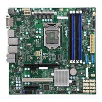
Supero X11SAE-M User Manual (131 pages)
Brand:
Supero
| Category:
Motherboard
| Size: 7 MB
Table of Contents
Manual Organization
3
Preface
3
Checklist
4
Conventions Used in the Manual
4
Standardized Warning Statements
5
Battery Handling
5
Product Disposal
6
Contacting Supermicro
8
Where to Find more Information
9
Table of Contents
10
Chapter 1 Introduction
21
Overview
21
About this Motherboard
21
Chipset Overview
21
Intel C236 Express Chipset Features
21
Motherboard Features
22
Special Features
24
Recovery from AC Power Loss
24
PC Health Monitoring
24
Fan Status Monitor with Firmware Control
24
Environmental Temperature Control
24
System Resource Alert
25
ACPI Features
25
Slow Blinking LED for Suspend-State Indicator
25
Power Supply
26
Super I/O
26
Jumper Description
31
Default Setting
31
Chapter 2 Installation
34
Installation Components and Tools Needed
34
Static-Sensitive Devices
35
Precautions
35
Unpacking
35
Processor and Heatsink Installation
36
Installing the LGA1151 Processor
36
Installing an Active CPU Heatsink with Fan
39
Removing the Heatsink
41
Installing DDR4 Memory
42
DIMM Installation
42
Removing Memory Modules
42
Memory Support
43
Memory Population Guidelines
44
Motherboard Installation
45
Tools Needed
45
Location of Mounting Holes
45
Installing the Motherboard
46
Connectors/Io Ports
47
Back I/O Panel
47
Universal Serial Bus (USB)
48
Ethernet Port / IPMI Port
49
Back Panel High Definition Audio (HD Audio)
49
VGA Port
50
DVI-D Port
50
VESA® Displayport
50
HDMI Port
50
Front Control Panel
51
Front Control Panel Pin Definitions
52
Power LED
52
Hdd Led
52
Nic1/Nic2 (Lan1/Lan2)
52
Overheat (Oh)/Fan Fail
52
Reset Button
53
Power Button
53
Connecting Cables
54
ATX Main PWR & CPU PWR Connectors (JPW1 & JPW2)
54
Fan Headers (Fan 1 ~ Fan 5)
55
Chassis Intrusion (JL1)
55
Internal Buzzer (SP1)
56
Speaker (JD1)
56
Onboard Power LED (JLED1)
57
Serial Ports (COM1/COM2)
57
DOM PWR Connector (JSD1)
58
Standby Power Header (JSTBY1)
59
PCI-E M.2 Connector (PCI-E M.2)
59
Front Panel Audio Header (AUDIO FP)
60
Power Supply I2C (JPI2C1)
60
I-SGPIO1/ I-SGPIO2 Headers
61
Jumper Settings
62
Explanation of Jumpers
62
LAN Enable/Disable
62
Clear CMOS
63
PCI Slot SMB Enable (JI2C1/JI2C2)
63
BMC Enable (JPB1)
63
Audio Enable (JPAC1)
64
HD Audio Enable (JHD_AC1)
64
Watch Dog Enable/Disable
64
Onboard VGA Enable/Disable (JPG1)
65
Manufacturing Mode (JPME2)
65
BIOS Restore (BIOS RESTORE)
66
Onboard Indicators
67
LAN Leds
67
Onboard Power LED (LED1)
67
Onboard Standby Power LED (LED3)
68
BMC/IPMI Heartbeat LED (LEDM1)
68
Uid Led (Led4)
68
SATA Connections
69
SATA Connections (I-SATA0~I-SATA7)
69
Chapter 3 Troubleshooting
70
Troubleshooting Procedures
70
Before Power on
70
No Power
70
No Video
71
Memory Errors
71
When the System Is Losing the Setup Configuration
71
Technical Support Procedures
72
Frequently Asked Questions
73
Battery Removal and Installation
74
Battery Removal
74
Proper Battery Disposal
74
Returning Motherboard for Service
75
Battery Installation
75
Chapter 4 BIOS
76
Introduction
76
Main Setup
77
System Date/System Time
77
Supermicro X11SAE/X11SAE-F
77
BIOS Version
77
Build Date
78
Memory Information
78
Total Memory
78
Memory Speed
78
Advanced Setup Configurations
79
Boot Feature
79
Quiet Boot
79
Addon ROM Display Mode
79
Bootup Numlock State
80
Wait for 'F1' if Error
80
INT19 (Interrupt 19) Trap Response
80
Re-Try Boot
80
Power Configuration
80
Watch Dog Function
80
Power Button Function
80
Restore on AC Power Loss
80
CPU Configuration
81
Hyper-Threading (Available When Supported by the CPU)
81
Active Processor Cores
82
Intel ® Virtualization Technology
82
Hardware Prefetcher (Available When Supported by the CPU)
82
Adjacent Cache Line Prefetch (Available When Supported by the CPU)
82
Cpu Aes
82
Boot Performance Mode
82
Hardware P-States (HWP)
82
Intel ® Speedstep
82
Turbo Mode
83
Package Power Limit MSR Lock
83
Power Limit 1 Override
83
Power Limit 2 Override
83
Power Limit 2
83
1-Core Ratio Limit Override
83
CPU C-States
84
Enhanced C-States
84
C-State Auto Demotion
84
C-State Un-Demotion
84
Package C-State Demotion
84
Package C-State Un-Demotion
84
C-State Pre-Wake
84
Package C-State Limit
84
Chipset Configuration
85
System Agent (SA) Configuration
85
VT-D
85
Gaussian Mixture Model
85
Internal Graphics
86
Aperture Size
86
Memory Configuration
89
PCH-IO Configuration
90
Port 61H Bit-4 Emulation
92
Pcie PLL SSC
92
USB 3.1 Device
92
SATA Configuration
92
SATA Controller(S)
92
SATA Mode Selection
92
SATA Frozen
92
If the Item above "SATA Mode Selection" Is Set to RAID, the Following Items will Display
92
Pcie/Pci/Pnp Configuration
93
PCI Latency Timer
93
PCI PERR/SERR Support
93
Above 4G Decoding (Available if the System Supports 64-Bit PCI Decoding)
93
SLOT1 PCI 33Mhz OPROM
93
SLOT2 PCI 33Mhz OPROM
93
Pch Slot3 Pci-E 3.0 X1 Oprom
94
Cpu Slot4 Pci-E 3.0 X8 (in X16) Oprom
94
Cpu Slot6 Pci-E 3.0 X16 Oprom
94
Pch Slot7 Pci-E 3.0 X1 Oprom
94
Onboard LAN Option ROM Type
94
Onboard LAN1 Option ROM
94
Onboard LAN2 Option ROM
94
Onboard Video Option ROM
94
Network Stack
94
Ipv4 PXE Support
94
Ipv6 PXE Support
95
Serial Port 2
96
PCH-FW Configuration
97
COM1 Console Redirection Settings
98
COM1 Legacy os Redirection Resolution
99
COM1 Putty Keypad
99
COM1 Redirection after BIOS POST
99
Com2
99
COM2 Console Redirection
99
COM1 Flow Control
99
COM2 Console Redirection Settings
100
COM2 Terminal Type
100
COM2 Bits Per Second
100
COM2 Data Bits
100
COM2 Parity
100
COM2 Stop Bits
100
COM2 Flow Control
101
COM2 VT-UTF8 Combo Key Support
101
COM2 Recorder Mode
101
COM2 Resolution 100X31
101
COM2 Legacy os Redirection Resolution
101
COM2 Putty Keypad
101
COM2 Redirection after BIOS Post
101
Bmc Sol
101
COM3 Console Redirection
101
COM3 Console Redirection Settings
102
COM3 Terminal Type
102
COM3 Bits Per Second
102
COM3 Data Bits
102
COM3 Parity
102
COM3 Stop Bits
102
COM3 Flow Control
103
COM3 VT-UTF8 Combo Key Support
103
COM3 Recorder Mode
103
COM3 Resolution 100X31
103
COM3 Legacy os Redirection Resolution
103
COM3 Putty Keypad
103
COM3 Redirection after BIOS Post
103
EMS (Emergency Management Services) Console Redirection
103
Amt Sol
103
Console Redirection
103
EMS Console Redirection Settings
104
Out-Of-Band Management Port
104
Terminal Type
104
ACPI Settings
105
TXT Support
106
Blink Leds
107
Link Status
108
MAC Address
108
Intel I219 Gigabit Network Connection
108
Event Logs
109
Change SMBIOS Event Log Settings
109
Enabling/Disabling Options
109
SMBIOS Event Log
109
Erasing Settings
109
Erase Event Log
109
When Log Is Full
109
SMBIOS Event Long Standard Settings
110
Log System Boot Event
110
Meci
110
Metw
110
View SMBIOS Event Log
110
Ipmi
111
BMC Firmware Revision
111
IPMI Status (Baseboard Management Controller)
111
System Event Log
111
Enabling/Disabling Options
111
SEL Components
111
Erasing Settings
111
Erase SEL
112
When SEL Is Full
112
BMC Network Configuration
112
IPMI LAN Selection
112
IPMI Network Link Status
112
Update IPMI LAN Configuration
112
Configuration Address Source
112
Security
113
Password Check
114
Administrator Password
114
Secure Boot Menu
114
Secure Boot
114
Secure Boot Mode
114
CSM Support
114
Key Management
114
Provision Factory Default Keys
114
Enroll All Factory Default Keys
114
Save All Secure Boot Variables
115
Platform Key (PK)
115
Set New Key
115
Key Exchange Key
115
Append Key
115
Authorized Signatures
115
Forbiden Signatures
115
Authorized Timestamps
116
Set New Key
116
Append Key
116
Boot
117
Fixed Boot Order Priorities
117
Delete Boot Option
118
UEFI Application Boot Priorities
118
Save & Exit
119
Discard Changes and Exit
119
Save Changes and Reset
119
Save Changes
119
Discard Changes
119
Default Options
120
Restore Optimized Defaults
120
Save as User Defaults
120
Restore User Defaults
120
Boot Override
120
Appendix A BIOS Error Beep Codes
121
BIOS Error Beep Codes
121
Appendix B Software Installation Instructions
123
Installing Drivers
123
Configuring Superdoctor ® III
124
Appendix C UEFI BIOS Recovery Instructions
127
An Overview to the UEFI BIOS
127
How to Recover the UEFI BIOS Image (-The Main BIOS Block
127
To Recover the Main BIOS Block Using a USB-Attached Device
128
Advertisement
Advertisement
Related Products
Supero X11SAE
Supero X11SAE-F
Supero X10SLQ
Supero X10SLL-SF
Supero X10DAi
Supero X10SRi-F
Supero X10SBA-V
Supero X10DRG-Q
Supero X10DDW-iN
Supero X10DDW-i
Supero Categories
Motherboard
Server
Chassis
Computer Hardware
Desktop
More Supero Manuals
Login
Sign In
OR
Sign in with Facebook
Sign in with Google
Upload manual
Upload from disk
Upload from URL