Table of Contents
Advertisement
Quick Links
Advertisement
Table of Contents

Related Manuals for Supero X10SRW-F


Summary of Contents for Supero X10SRW-F
- Page 1 X10SRW-F USER’S MANUAL Revision 1.0...
- Page 2 The information in this User’s Manual has been carefully reviewed and is believed to be accurate. The vendor assumes no responsibility for any inaccuracies that may be contained in this document, makes no commitment to update or to keep current the information in this manual, or to notify any person or organization of the updates.
-
Page 3: Preface
This manual is written for system integrators, IT professionals, and knowledgeable end users. It provides information for the installation and use of the X10SRW-F motherboard. About This Motherboard X10SRW-F supports a single Intel ® E5-2600/1600 Series Processor in an LGA2011 R3 socket. With the Intel ®... -
Page 4: Conventions Used In The Manual
X10SRW-F User’s Manual Conventions Used in the Manual: Special attention should be given to the following symbols for proper system instal- lation: Warning: Critical information given to prevent damage to the components or injury to yourself. Note: Additional Information provided for correct system setup. -
Page 5: Contacting Supermicro
Contacting Supermicro Contacting Supermicro Headquarters Address: Super Micro Computer, Inc. 980 Rock Ave. San Jose, CA 95131 U.S.A. Tel: +1 (408) 503-8000 Fax: +1 (408) 503-8008 Email: marketing@supermicro.com (General Information) support@supermicro.com (Technical Support) Web Site: www.supermicro.com Europe Address: Super Micro Computer B.V. Het Sterrenbeeld 28, 5215 ML 's-Hertogenbosch, The Netherlands Tel:... -
Page 6: Table Of Contents
X10SRW-F User’s Manual Table of Contents Preface About This Motherboard ....................iii Manual Organization ..................... iii Conventions Used in the Manual ..................iv Contacting Supermicro ....................v Chapter 1 Introduction Overview ......................1-1 Checklist ......................1-1 Motherboard Features ..................1-7 Chipset Overview ..................1-10 Intel C612 Express Chipset Features ............ - Page 7 Table of Contents DIMM Installation ..................2-13 Removing Memory Modules ................. 2-14 Memory Support .................... 2-14 Memory Population Guidelines ..............2-14 Connectors/IO Ports ..................2-17 Backplane I/O Panel ..................2-17 Universal Serial Bus (USB) ..............2-18 Ethernet Ports ..................2-19 Serial Ports (COM1/COM2)..............
- Page 8 Main Setup ...................... 4-2 The following Main menu items will be displayed: ........4-2 System Date/System Time ................ 4-3 Supermicro X10SRW-F ................4-3 BIOS Version: This item displays the version of the BIOS ROM used in the system......................4-3 Build Date: This item displays the date when the version of the BIOS ROM used in the system was built.
- Page 9 Table of Contents system......................4-3 Memory Speed: This item displays the default speed of the memory modules installed in the system..............4-3 Advanced Setup Configurations..............4-4 Boot Feature ....................4-4 Quiet Boot ....................4-4 AddOn ROM Display Mode ................ 4-4 Bootup Num-Lock ..................
- Page 10 X10SRW-F User’s Manual QPI (Quick Path Interconnect) Configuration ..........4-13 South Bridge ....................4-17 Legacy USB Support ................4-17 XHCI Hand-Off ..................4-17 EHCI Hand-Off ..................4-17 USB Mass Storage Driver Support ............4-17 Port 60/64 Emulation ................4-17 USB 3.0 Support ..................
- Page 11 Table of Contents ASPM Support ..................4-24 MMIOHBase ..................... 4-25 MMIO High Size ..................4-25 RSC-R2UW-2E8R Slot1 PCI-E x8 (OPROM)/RSC-R2UW-4E8 Slot4 PCI-E x8 (OPROM)/RSC-R2UW-4E8 Slot3 PCI-E x8 (OPROM)/RSC-R2UW-4E8 Slot1 PCI-E x8 (OPROM)/ RSC-R2UW-4E8 Slot2 PCI-E x8 (OPROM) . 4-25 Onboard LAN1 Option ROM/Onboard LAN2 Option ROM ...... 4-25 VGA Priority ....................
- Page 12 X10SRW-F User’s Manual Runtime Error Logging Support ............... 4-33 Memory Corrected Error Enabling (Available when the item above-Runtime Error Logging Support is set to Enable) ..........4-33 PCI-Ex (PCI-Express) Error Enable ............4-33 Memory Correctable Error Threshold ............4-33 Erasing Settings ..................4-34 Erase Event Log ..................
- Page 13 Table of Contents Save & Exit ....................4-41 Discard Changes and Exit ..............4-41 Save Changes and Reset ................ 4-41 Save Options .................... 4-41 Save Changes ..................4-41 Discard Changes ..................4-41 Restore Defaults ..................4-41 Save As User Defaults ................4-42 Restore User Defaults ................
- Page 14 X10SRW-F User’s Manual Notes...
-
Page 15: Chapter 1 Introduction
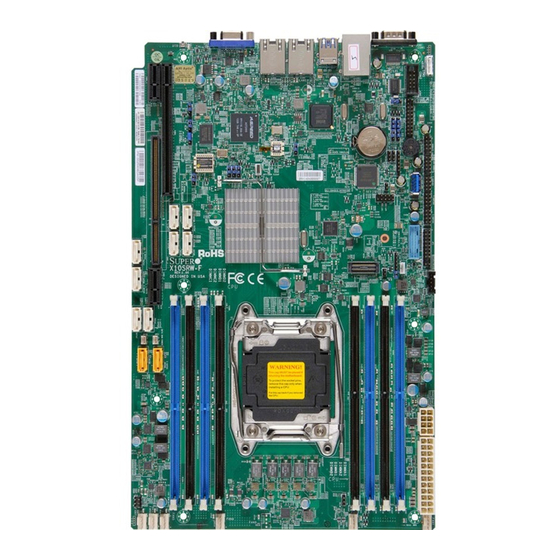
Chapter 1: Introduction Chapter 1 Introduction Overview Checklist Congratulations on purchasing your computer motherboard from an acknowledged leader in the industry. Supermicro boards are designed with the utmost attention to detail to provide you with the highest standards in quality and performance. Please check that the following items have all been included with your motherboard. - Page 16 X10SRW-F User’s Manual X10SRW-F Motherboard Image Note: All graphics shown in this manual were based upon the latest PCB Revision available at the time of publishing of the manual. Your motherboard or components may or may not look exactly the same as the graphics shown in this manual.
- Page 17 Chapter 1: Introduction X10SRW-F Motherboard Layout JUIDB1 COM1 USB0/1(3.0) BIOS COM2 LICENSE LAN2 LAN1 USB2/3 IPMI_LAN JPL1/LAN JPL1 1-2:ENABLE 2-3:DISABLE LEDM1 JPG1 JPF1 JPG1:VGA ON:POWER FORCE ON 1-2:ENABLE 2-3:DISABLE JBT1 USB8(3.0) JPB1 JL1: CHASSIS INTRUSION T-SGPIO3 (SATA SGPIO2) T-SGPIO2 (SATA SGPIO1)
- Page 18 X10SRW-F User’s Manual X10SRW-F Quick Reference JUIDB1 COM1 USB0/1(3.0) BIOS COM2 LICENSE LAN2 LAN1 USB2/3 IPMI_LAN JPL1/LAN JPL1 1-2:ENABLE 2-3:DISABLE LEDM1 JPG1 JPF1 JPG1:VGA ON:POWER FORCE ON 1-2:ENABLE 2-3:DISABLE JBT1 USB8(3.0) JPB1 JL1: CHASSIS INTRUSION T-SGPIO3 (SATA SGPIO2) T-SGPIO2 (SATA SGPIO1)
- Page 19 Chapter 1: Introduction X10SRW-F Headers/Connectors Connector Description Onboard Battery COM1/COM2 COM1 (Port)/COM2 (Header) FAN1-2, FAN4-7 System/CPU Fan Headers 24-pin Main ATX Power Connector Speaker/Buzzer (Pins 1-3: Power LED, Pins 4-7: Speaker) Front Panel Control Header JIPMB1 System Management Bus Header for the IPMI Slot...
- Page 20 X10SRW-F User’s Manual X10SRW-F LED Indicators Description State/Color Status UID LED Blue: On Unit Identified LEDM1 BMC Heartbeat LED Green: Blinking BMC Normal...
-
Page 21: Motherboard Features
Chapter 1: Introduction Motherboard Features Single Intel ® E5-2600/1600 Series Processor in an LGA2011 R3 socket. Memory Eight (8) ECC/Non-ECC DDR4 RDIMM/LRDIMM/UDIMM at 1333/1600/1866/2133 MHz memory (1 DPC) up to 256GB RDIMM, 512GB LRDIMM, or 64GB UDIMM. Dual-channel memory DIMM sizes RDIMM 1 GB, 2 GB, 4GB, 8GB, 16GB, and 32GB... - Page 22 X10SRW-F User’s Manual PC Health Monitoring CPU Monitoring Onboard voltage monitors for CPU core, +3.3V, +5V,+12V, +3.3V Stdby, VBAT, Memory, PCH and BMC voltage CPU 5-phase switching voltage CPU/System overheat LED and control CPU Thermal Trip support Thermal Monitor support...
- Page 23 Chapter 1: Introduction X10SRW-F Block Diagram VR12.5 5 PHASE 145W CHA,B SNB CORE DDR-IV CHC,D DMI2 PCI-E X16 G3 PCI-E X16G3 DMI2 PCI-E X8 G3 4GB/s PCI-E X4 I350 RJ45 LAN1 PCI-E X4 (#5..8) RJ45 LAN2 6.0 Gb/S RGRMII LAN3...
-
Page 24: Chipset Overview
Direct Media Interface (DMI) for chip-to-chip true isochronous communication, providing up to 5 GT/s of software-transparent data transfer rate on each read/write direction. In addition, the X10SRW-F also features a TCO timer which allows the system to recover from a software/hardware lock and perform tasks, including Function Disable and Intruder Detect. -
Page 25: Special Features
Chapter 1: Introduction Special Features Recovery from AC Power Loss Basic I/O System (BIOS) provides a setting for you to determine how the system will respond when AC power is lost and then restored to the system. You can choose for the system to remain powered off, (in which case you must press the power switch to turn it back on), or for it to automatically return to a power-on state. -
Page 26: Acpi Features
X10SRW-F User’s Manual ACPI Features ACPI stands for Advanced Configuration and Power Interface. The ACPI specifica- tion defines a flexible and abstract hardware interface that provides a standard way to integrate power management features throughout a PC system, including its hardware, operating system and application software. This enables the system to automatically turn on and off peripherals such as CD-ROMs, network cards, hard disk drives and printers. -
Page 27: Super I/O
Chapter 1: Introduction Super I/O The Super I/O supports two high-speed, 16550 compatible serial communication ports (UARTs). Each UART includes a 16-byte send/receive FIFO, a programmable baud rate generator, complete modem control capability and a processor interrupt system. Both UARTs provide legacy speed with baud rate of up to 115.2 Kbps as well as an advanced speed with baud rates of 250 K, 500 K, or 1 Mb/s, which support higher speed modems. - Page 28 X10SRW-F User’s Manual Notes 1-14...
-
Page 29: Chapter 2 Installation
Chapter 2: Installation Chapter 2 Installation Standardized Warning Statements The following statements are industry-standard warnings, provided to warn the user of situations which have the potential for bodily injury. Should you have questions or experience difficulty, contact Supermicro's Technical Support department for assis- tance. - Page 30 X10SRW-F User’s Manual Attention Danger d'explosion si la pile n'est pas remplacée correctement. Ne la remplacer que par une pile de type semblable ou équivalent, recommandée par le fabricant. Jeter les piles usagées conformément aux instructions du fabricant. ¡Advertencia! Existe peligro de explosión si la batería se reemplaza de manera incorrecta. Re- emplazar la batería exclusivamente con el mismo tipo o el equivalente recomen-...
-
Page 31: Product Disposal
Chapter 2: Installation Product Disposal Warning! Ultimate disposal of this product should be handled according to all national laws and regulations. 製品の廃棄 この製品を廃棄処分する場合、 国の関係する全ての法律 ・ 条例に従い処理する必要が あり ます。 警告 本产品的废弃处理应根据所有国家的法律和规章进行。 警告 本產品的廢棄處理應根據所有國家的法律和規章進行。 Warnung Die Entsorgung dieses Produkts sollte gemäß allen Bestimmungen und Gesetzen des Landes erfolgen. -
Page 32: Static-Sensitive Devices
X10SRW-F User’s Manual القىانين واللىائح الىطنية جميع وفقا ل ينبغي التعامل معه هذا المنتج من التخلص النهائي عند 경고! 이 제품은 해당 국가의 관련 법규 및 규정에 따라 폐기되어야 합니다. Waarschuwing De uiteindelijke verwijdering van dit product dient te geschieden in overeenstemming met alle nationale wetten en reglementen. -
Page 33: Motherboard Installation
(SATA SGPIO2) T-SGPIO2 (SATA SGPIO1) T-SGPIO2 USB9/10 T-SGPIO1 (SATA SGPIO0) T-SGPIO1 JUSB3-1A JOH1 JSTBY1 X10SRW-F REV: 1.01 DESIGNED IN USA JSD2 JSD1 LGA2011-3 JVR1 FAN4 FAN3 FAN2 FAN1 Caution: 1) To avoid damaging the motherboard and its components, please do not use a force greater than 8 lb/inch on each mounting screw during motherboard installation. -
Page 34: Installing The Motherboard
X10SRW-F User’s Manual Installing the Motherboard 1. Install the I/O shield into the back of the chassis. 2. Locate the mounting holes on the motherboard. (See the previous page.) 3. Locate the matching mounting holes on the chassis. Align the mounting holes on the motherboard against the mounting holes on the chassis. -
Page 35: Processor And Heatsink Installation
Chapter 2: Installation Processor and Heatsink Installation Warning: When handling the processor package, avoid placing direct pressure on the label area of the fan. Notes: • Always connect the power cord last, and always remove it before adding, re- moving or changing any hardware components. Make sure that you install the processor into the CPU socket before you install the CPU heatsink. - Page 36 X10SRW-F User’s Manual 2. Press the second load lever labeled 'Close 1st' to release the load plate that covers the CPU socket from its locking position. Pull lever away from Press down on Load the socket Lever 'Close 1st' 3. With the 'Close 1st' lever fully retracted, gently push down on the 'Open 1st' lever to open the load plate.
- Page 37 Chapter 2: Installation 4. Using your thumb and the index finger, loosen the CPU lever and open the load plate. 5. Use your thumb and index finger to hold the CPU on its edges. Align the CPU keys, which are semi-circle cutouts, against the socket keys. Socket Keys CPU Keys 6.
- Page 38 X10SRW-F User’s Manual 7. With the CPU inside the socket, inspect the four corners of the CPU to make sure that the CPU is properly installed. 8. Close the load plate with the CPU inside the socket. Lock the lever labelled 'Close 1st' first, then lock the lever labelled 'Open 1st' second.
-
Page 39: Installing A Passive Cpu Heatsink
Chapter 2: Installation Installing a Passive CPU Heatsink 1. Do not apply any thermal grease to the heatsink or the CPU die -- the re- quired amount has already been applied. 2. Place the heatsink on top of the CPU so that the four mounting holes are aligned with those on the Motherboard's and the Heatsink Bracket under- neath. -
Page 40: Removing The Heatsink
X10SRW-F User’s Manual Removing the Heatsink Warning: We do not recommend that the CPU or the heatsink be removed. However, if you do need to uninstall the heatsink, please follow the instructions below to prevent damage to the CPU or the CPU socket. -
Page 41: Installing Ddr4 Memory
(SATA SGPIO0) T-SGPIO1 JUSB3-1A the system to work properly, please use the memory modules of the JOH1 JSTBY1 X10SRW-F same type and speed in the same REV: 1.01 DESIGNED IN USA motherboard. JSD2 JSD1 2. Push the release tabs outwards on... -
Page 42: Removing Memory Modules
Please refer to the table below: Memory Population Guidelines Please follow the table below when populating the X10SRW-F. DDR4 Unbuffered ECC (UDIMM) Memory DIMM Slots per... - Page 43 Chapter 2: Installation Populating RDIMM Memory Modules 2 Slots per Channel RDIMM Population Configurations Configuration POR Speed 1-Node or DIMM1 DIMM0 Number 2-Node DDR4-2133, Empty Single-rank 1866, 1600 DDR4-2133, Empty Dual-rank 1866, 1600 DDR4-1866, Single-rank Single-rank 1600 DDR4-1866, Single-rank Dual-rank 1600 DDR4-1866, Dual-rank...
- Page 44 X10SRW-F User’s Manual Notes: • Be sure to use memory modules of the same type, speed, and frequency on the same motherboard. Mixing of memory modules of different types and speeds is not allowed. • Due to memory allocation to system devices, the amount of memory that remains available for operational use will be reduced when 4 GB of RAM is used.
-
Page 45: Connectors/Io Ports
INTRUSION T-SGPIO3 (SATA SGPIO2) T-SGPIO2 (SATA SGPIO1) T-SGPIO2 USB9/10 T-SGPIO1 (SATA SGPIO0) T-SGPIO1 JUSB3-1A JOH1 JSTBY1 X10SRW-F REV: 1.01 DESIGNED IN USA JSD2 JSD1 LGA2011-3 JVR1 FAN4 FAN3 FAN2 FAN1 Backplane I/O Panel A. COM1 F. USB Port 4 (3.0) B. -
Page 46: Universal Serial Bus (Usb)
X10SRW-F User’s Manual Universal Serial Bus (USB) Four Universal Serial Bus ports (USB 3.0 ports 0/1 and USB 2.0 ports 2/3) are located on the I/O back panel. In addition, three USB 2.0 headers (USB 4/5, 6/7, 9/10), and two USB 3.0 headers (USB 8 (Type A), USB 11/12) are also located on the motherboard to provide USB 3.0 support using USB cables (not included). -
Page 47: Ethernet Ports
JBT1 USB8(3.0) JPB1 D. COM1 JL1: CHASSIS INTRUSION T-SGPIO3 (SATA SGPIO2) T-SGPIO2 (SATA SGPIO1) T-SGPIO2 USB9/10 T-SGPIO1 (SATA SGPIO0) E. COM2 T-SGPIO1 JUSB3-1A JOH1 JSTBY1 X10SRW-F REV: 1.01 DESIGNED IN USA JSD1 JSD2 LGA2011-3 JVR1 FAN4 FAN2 FAN3 FAN1 2-19... -
Page 48: Unit Identifier Switch/Uid Led Indicator
X10SRW-F User’s Manual Unit Identifier Switch/UID LED Indicator UID Switch A Unit Identifier (UID) switch and an LED Pin# Definition Indicator are located on the motherboard. Ground The UID switch is located next to the VGA Ground port on the backplane. The UID LED (LE1) Button In is located next to the UID switch. -
Page 49: Front Control Panel
JL1: CHASSIS INTRUSION T-SGPIO3 (SATA SGPIO2) T-SGPIO2 (SATA SGPIO1) T-SGPIO2 USB9/10 T-SGPIO1 (SATA SGPIO0) T-SGPIO1 JUSB3-1A JOH1 JSTBY1 X10SRW-F REV: 1.01 DESIGNED IN USA JSD2 JSD1 LGA2011-3 JVR1 FAN4 FAN3 FAN2 FAN1 JF1 Header Pins Ground Power LED HDD LED... -
Page 50: Front Control Panel Pin Definitions
X10SRW-F User’s Manual Front Control Panel Pin Definitions NMI Button NMI Button Pin Definitions (JF1) The non-maskable interrupt button Pin# Definition header is located on pins 19 and 20 Control of JF1. Refer to the table on the right Ground for pin definitions. -
Page 51: Hdd Led
(SATA SGPIO2) T-SGPIO2 (SATA SGPIO1) T-SGPIO2 USB9/10 T-SGPIO1 (SATA SGPIO0) T-SGPIO1 JUSB3-1A Ground JOH1 JSTBY1 Power LED X10SRW-F REV: 1.01 HDD LED DESIGNED IN USA NIC1 LED JSD1 JSD2 NIC2 LED OH/Fan Fail LED PWR Fail LED LGA2011-3 Reset Reset Button... -
Page 52: Overheat (Oh)/Fan Fail/Pwr Fail/Uid Led
X10SRW-F User’s Manual Overheat (OH)/Fan Fail/PWR Fail/ OH/Fan Fail/ PWR Fail/Blue_UID UID LED LED Pin Definitions (JF1) Pin# Definition Connect an LED cable to pins 7 and P5V_STB 8 of Front Control Panel to use the Red_LED-Cathode/OH/Fan Fail/ Overheat, Fan Fail, and Power Fail Power Fail connections. -
Page 53: Reset Button
T-SGPIO2 (SATA SGPIO1) T-SGPIO2 USB9/10 T-SGPIO1 (SATA SGPIO0) T-SGPIO1 Ground JUSB3-1A JOH1 Power LED JSTBY1 HDD LED X10SRW-F REV: 1.01 DESIGNED IN USA NIC1 LED JSD2 JSD1 NIC2 LED OH/Fan Fail LED PWR Fail LED Reset Reset Button Ground LGA2011-3... -
Page 54: Connecting Cables
X10SRW-F User’s Manual Connecting Cables This section provides brief descriptions and pin-out definitions for onboard headers and connectors. Be sure to use the correct cable for each header or connector. For information on Backpanel USB and Front Panel USB ports, refer to page 2-17. -
Page 55: Fan Headers (Fan 1-2, Fan 4-7)
Chapter 2: Installation Fan Headers (Fan 1-2, Fan 4-7) Fan Header Pin Definitions The X10SRW-F has six fan headers (Fan 1-2, Pin# Definition Fan 4-7). These fans are 4-pin fan headers. Ground (Black) Although pins 1-3 of the onboard fan headers 2.5A/+12V... -
Page 56: Internal Speaker/Buzzer (Sp1)
X10SRW-F User’s Manual Internal Speaker/Buzzer (SP1) Internal Buzzer Pin Definition The Internal Speaker/Buzzer (SP1) is Pin# Definitions used to provide audible indications for Pin 1 Pos. (+) Beep In various beep codes. See the table on Pin 2 Neg. (-) Alarm the right for pin definitions. -
Page 57: Dom Pwr Connector (Jsd1)
ON:POWER FORCE ON 1-2:ENABLE 2-3:DISABLE JBT1 USB8(3.0) JPB1 JL1: CHASSIS INTRUSION T-SGPIO3 (SATA SGPIO2) T-SGPIO2 (SATA SGPIO1) T-SGPIO2 USB9/10 T-SGPIO1 (SATA SGPIO0) T-SGPIO1 JUSB3-1A JOH1 JSTBY1 X10SRW-F REV: 1.01 DESIGNED IN USA JSD2 JSD1 LGA2011-3 JVR1 FAN4 FAN2 FAN3 FAN1 2-29... -
Page 58: T-Sgpio 1/2/3 Headers
X10SRW-F User’s Manual T-SGPIO 1/2/3 Headers T-SGPIO/6-SGPIO Pin Definitions Three Serial-Link General Purpose Input/ Pin# Definition Definition Output headers (T-SGPIO 1/2/3) are located on the motherboard. T-SGPIO Data Ground 1/2/3 support onboard SATA interface. Ground Load See the table on the right for pin defini- Clock tions. -
Page 59: Tpm Header/Port 80 Header
ON:POWER FORCE ON 1-2:ENABLE 2-3:DISABLE JBT1 USB8(3.0) JPB1 JL1: CHASSIS INTRUSION T-SGPIO3 (SATA SGPIO2) T-SGPIO2 (SATA SGPIO1) T-SGPIO2 USB9/10 T-SGPIO1 (SATA SGPIO0) T-SGPIO1 JUSB3-1A JOH1 JSTBY1 X10SRW-F REV: 1.01 DESIGNED IN USA JSD2 JSD1 LGA2011-3 JVR1 FAN4 FAN2 FAN3 FAN1 2-31... -
Page 60: Jumper Settings
X10SRW-F User’s Manual Jumper Settings Explanation of Jumpers To modify the operation of the mother- board, jumpers can be used to choose between optional settings. Jumpers create shorts between two pins to change the function of the connector. Pin 1 is identified with a square solder pad on the printed circuit board. -
Page 61: Cmos Clear (Jbt1)
ON:POWER FORCE ON 1-2:ENABLE 2-3:DISABLE JBT1 USB8(3.0) JPB1 JL1: CHASSIS INTRUSION T-SGPIO3 (SATA SGPIO2) T-SGPIO2 (SATA SGPIO1) T-SGPIO2 USB9/10 T-SGPIO1 (SATA SGPIO0) T-SGPIO1 JUSB3-1A JOH1 JSTBY1 X10SRW-F REV: 1.01 DESIGNED IN USA JSD2 JSD1 LGA2011-3 JVR1 FAN4 FAN2 FAN3 FAN1 2-33... -
Page 62: Vga Enable
X10SRW-F User’s Manual VGA Enable VGA Enable Jumper Settings Jumper JPG1 allows the user to enable Jumper Setting Definition the onboard VGA connector. The default Enabled (Default) setting is 1-2 to enable the connection. Disabled See the table on the right for jumper settings. -
Page 63: Watch Dog Enable/Disable
ON:POWER FORCE ON 1-2:ENABLE 2-3:DISABLE JBT1 USB8(3.0) JPB1 JL1: CHASSIS INTRUSION T-SGPIO3 (SATA SGPIO2) T-SGPIO2 (SATA SGPIO1) T-SGPIO2 USB9/10 T-SGPIO1 (SATA SGPIO0) T-SGPIO1 JUSB3-1A JOH1 JSTBY1 X10SRW-F REV: 1.01 DESIGNED IN USA JSD1 JSD2 LGA2011-3 JVR1 FAN4 FAN2 FAN3 FAN1 2-35... -
Page 64: Onboard Indicators
X10SRW-F User’s Manual Onboard Indicators LAN1/LAN2 Activity LED Link LED LAN 1/LAN 2 LEDs Two LAN ports (LAN 1/LAN 2) are located GLAN 1/2 Activity Indicator on the I/O backplane of the motherboard. LED Settings Each Ethernet LAN port has two LEDs. -
Page 65: Bmc Heartbeat Led (Ledm1)
BMC Heartbeat LED (LEDM1) BMC Heartbeat LED Status A BMC Heartbeat LED is located at Color/State Definition LEDM1 on the X10SRW-F. See the table Green: BMC: Normal on the right for more information. Blinking Unit Identification LED (LE1) UID LED Status... -
Page 66: Onboard Power Led (Le2)
X10SRW-F User’s Manual Onboard Power LED (LE2) Onboard PWR LED Indicator LED Status An Onboard Power LED is located Color/Status Definition at LE2 on the motherboard. When System Off LE2 is on, the AC power cable is Grenn: On System on connected. -
Page 67: 2-10 Sata Connections
JPB1 JL1: CHASSIS INTRUSION T-SGPIO3 I. S-SATA 2 (SATA SGPIO2) T-SGPIO2 (SATA SGPIO1) T-SGPIO2 USB9/10 T-SGPIO1 (SATA SGPIO0) T-SGPIO1 J. S-SATA 3 JUSB3-1A JOH1 JSTBY1 X10SRW-F REV: 1.01 DESIGNED IN USA JSD1 JSD2 LGA2011-3 JVR1 FAN4 FAN2 FAN3 FAN1 2-39... - Page 68 X10SRW-F User’s Manual 2-40...
-
Page 69: Chapter 3 Troubleshooting
Chapter 3: Troubleshooting Chapter 3 Troubleshooting Troubleshooting Procedures Use the following procedures to troubleshoot your system. If you have followed all of the procedures below and still need assistance, refer to the ‘Technical Support Procedures’ and/or ‘Returning Merchandise for Service’ section(s) in this chapter. Always disconnect the AC power cord before adding, changing or installing any hardware components. -
Page 70: No Video
X10SRW-F User’s Manual No Video 1. If the power is on, but you have no video--in this case, you will need to re- move all the add-on cards and cables first. 2. Use the speaker to determine if any beep codes exist. (Refer to Appendix A for details on beep codes.) -
Page 71: Technical Support Procedures
Chapter 3: Troubleshooting Technical Support Procedures Before contacting Technical Support, please make sure that you have followed all the steps listed below. Also, Note that as a motherboard manufacturer, Supermicro does not sell directly to end users, so it is best to first check with your distributor or reseller for troubleshooting services. -
Page 72: Frequently Asked Questions
Frequently Asked Questions Question: What type of memory does my motherboard support? Answer: The X10SRW-F supports up to 256GB of RDIMM and 512Gb of LRDIMM DDR4 1333/1600/2133 MHz in eight memory slots. See Section 2-5 for details on installing memory. -
Page 73: Battery Removal And Installation
Chapter 3: Troubleshooting Battery Removal and Installation Battery Removal To remove the onboard battery, follow the steps below: 1. Power off your system and unplug your power cable. 2. Locate the onboard battery as shown below. 3. Using a tool such as a pen or a small screwdriver, push the battery lock out- wards to unlock it. -
Page 74: Returning Merchandise For Service
X10SRW-F User’s Manual Returning Merchandise for Service A receipt or copy of your invoice marked with the date of purchase is required before any warranty service will be rendered. You can obtain service by calling your vendor for a Returned Merchandise Authorization (RMA) number. For faster service, you may also obtain RMA authorizations online (http://www.supermicro. -
Page 75: Chapter 4 Bios
BIOS Introduction This chapter describes the AMI BIOS setup utility for the X10SRW-F. The ROM BIOS is stored in a Flash EEPROM and can be easily updated. This chapter describes the basic navigation of the AMI BIOS setup utility screens. -
Page 76: How To Start The Setup Utility
X10SRW-F User’s Manual How to Start the Setup Utility Normally, the only visible Power-On Self-Test (POST) routine is the memory test. As the memory is being tested, press the <Delete> key to enter the main menu of the AMI BIOS setup utility. From the main menu, you can access the other setup screens. -
Page 77: System Date/System Time
Day MM/DD/YYYY format. The time is entered in HH:MM:SS format. Note: The time is in the 24-hour format. For example, 5:30 P.M. appears as 17:30:00. Supermicro X10SRW-F BIOS Version: This item displays the version of the BIOS ROM used in the system. -
Page 78: Advanced Setup Configurations
X10SRW-F User’s Manual Advanced Setup Configurations Use the arrow keys to select Advanced setup and press <Enter> to access the submenu items: Warning: Take Caution when changing the Advanced settings. An incorrect value, a very high DRAM frequency or an incorrect BIOS timing setting may cause the system to malfunction. -
Page 79: Wait For 'F1' If Error
Chapter 4: AMI BIOS Wait For 'F1' If Error Select Enabled to force the system to wait until the 'F1' key is pressed if an error occurs. The options are Disabled and Enabled. INT19 (Interrupt 19) Trap Response Interrupt 19 is the software interrupt that handles the boot disk function. When this item is set to Immediate, the ROM BIOS of the host adaptors will "capture"... -
Page 80: Restore On Ac Power Loss
X10SRW-F User’s Manual Restore on AC Power Loss Use this feature to set the power state after a power outage. Select Power-Off for the system power to remain off after a power loss. Select Power-On for the system power to be turned on after a power loss. Select Last State to allow the system to resume its last power state before a power loss. -
Page 81: Hyper-Threading
Chapter 4: AMI BIOS Hyper-Threading Select Enable to use Intel Hyper-Threading Technology to enhance CPU perfor- mance. The options are Enable and Disable. Performance/Watt Select Power Optimized to use Intel Turbo Boost Technology to maximize system performance (with maximum cooling) when performance state P0 lasts more than two seconds. -
Page 82: Dcu Ip Prefetcher
X10SRW-F User’s Manual DCU IP Prefetcher If this item is set to Enable, the IP prefetcher in the DCU (Data Cache Unit) will prefetch IP addresses to improve network connectivity and system performance. The options are Enable and Disable. DCU (Data Cache Unit) Mode Use this item to set the DCU data-prefecting mode. -
Page 83: Advanced Power Management Configuration
Chapter 4: AMI BIOS Advanced Power Management Configuration Power Technology Select Energy Efficient to support power-saving mode. Select Custom to custom- ize system power settings. Select Disabled to disable power-saving settings. The options are Disable, Energy Efficient, and Custom. Config TDP Select Enable to allow the user to configure the Thermal Design Power (TDP) settings for the system. - Page 84 X10SRW-F User’s Manual CPU C6 Report (Available when Power Technology is set to Custom) Select Enable to allow the BIOS to report the CPU C6 state (ACPI C3) to the operating system. During the CPU C6 state, power to all caches is turned off.
-
Page 85: Chipset Configuration
Chapter 4: AMI BIOS Short Duration Power Limit Enable Select Enable to support Short Duration Power Limit (Power Limit 2). The options are Enable and Disable. Short Duration Power Limit This item displays the time period during which short duration power is main- tained. - Page 86 X10SRW-F User’s Manual PORT 2A Link Speed Use this item to configure the link speed of a PCI-E port specified by the user. The options are Gen 1 (Generation 1) (2.5 GT/s), Gen 2 (Generation 2) (5 GT/s) and Gen 3 (Generation 3) (8 GT/s).
-
Page 87: Intel Vt For Directed I/O (Vt-D)
Chapter 4: AMI BIOS Intel VT for Directed I/O (VT-d) Intel VT for Direct I/O (VT-d) Intel VT for Directed I/O (VT-d) ® Select Enable to use Intel Virtualization Technology support for Direct I/O VT-d support by reporting the I/O device assignments to the VMM (Virtual Machine Monitor) through the DMAR ACPI Tables. - Page 88 X10SRW-F User’s Manual Link Speed Mode Use this item to select the data transfer speed for QPI Link connections. The options are Fast and Slow. Link Frequency Select Use this item to select the desired frequency for QPI Link connections. The op- tions are 6.4GB/s, 8.0GB/s, 9.6GB/s, Auto, and Auto Limited.
- Page 89 Chapter 4: AMI BIOS DRAM RAPL (Running Average Power Limit) Baseline Use this feature to set the run-time power-limit baseline for DRAM modules. The options are Disable, DRAM RAPL Mode 0, and DRAM RAPL Mode 1. Set Throttling Mode Throttling improves reliability and reduces power consumption in the proces- sor via automatic voltage control during processor idle states.
- Page 90 X10SRW-F User’s Manual Memory RAS (Reliability_Availability_Serviceability) Configuration Use this submenu to configure the following Memory RAS settings. RAS Mode Select Enable to enable RAS support to enhance reliability, availability and ser- viceability of onboard memory modules. The options are Enable and Disable.
-
Page 91: South Bridge
Chapter 4: AMI BIOS South Bridge The following South Bridge information will display:\ • USB Configuration • USB Module Version • USB Devices Legacy USB Support Select Enabled to support onboard legacy USB devices. Select Auto to disable legacy support if there are no legacy USB devices present. Select Disable to have all USB devices available for EFI applications only. -
Page 92: Ehci2
X10SRW-F User’s Manual EHCI2 Select Enabled to enable EHCI (Enhanced Host Controller Interface) support on USB 2.0 connector #2 (-at least one USB 2.0 connector should be enabled for EHCI support.) The options are Disabled and Enabled. XHCI Pre-Boot Drive Select Enabled to enable XHCI (Extensible Host Controller Interface) support on a pre-boot drive specified by the user. -
Page 93: If The Item Above "Configure Sata As" Is Set To Ide, The Following Items Will Display
Chapter 4: AMI BIOS SATA Port 0~ Port 5 This item displays the information detected on the installed SATA drive on the particular SATA port. • Model number of drive and capacity • Software Preserve Support Port 0~ Port 5 Select Enabled to enable a SATA port specified by the user. -
Page 94: If The Item Above "Configure Sata As" Is Set To Raid, The Following Items Will Display
X10SRW-F User’s Manual *If the item above "Configure SATA as" is set to RAID, the following items will display: Support Aggressive Link Power Management When this item is set to Enabled, the SATA AHCI controller manages the power usage of the SATA link. The controller will put the link in a low power mode during extended periods of I/O inactivity, and will return the link to an active state when I/O activity resumes. -
Page 95: Ssata Configuration
Chapter 4: AMI BIOS sSATA Configuration When this submenu is selected, the AMI BIOS automatically detects the presence of the SATA devices that are supported by the SCU controller and displays the following items: sSATA Controller This item enables or disables the onboard SATA controller supported by the Intel SCU chip. -
Page 96: If The Item Above "Configure Ssata As" Is Set To Ide, The Following Items Will Display
X10SRW-F User’s Manual sSATA Port 0 ~ Port 3 Spin Up Device On an edge detect from 0 to 1, set this item to allow the PCH to start a COMRE- SET initialization to the device. The options are Enabled and Disabled. -
Page 97: Server Me (Management Engine) Configuration
Chapter 4: AMI BIOS sSATA Port 0~ Port 3 Select Enabled to enable an sSATA port specified by the user. The options are Disabled and Enabled. sSATA Port 0 ~ Port 3 Hot Plug This feature designates this port for hot plugging. Set this item to Enabled for hot-plugging support, which will allow the user to replace an sSATA drive without shutting down the system. -
Page 98: Pci Aer (Advanced Error-Reporting) Support
X10SRW-F User’s Manual • PCI Latency Timer PCI AER (Advanced Error-Reporting) Support Use this item to configure the PCI-X latency timer for a device installed on a PCI-X bus. Select 64 to set the PCI-X latency timer to 64 PCI clock cycles. The options are 32, 64, 96, 128, 160, 192, 224 and 248 (PCI Bus Clocks). -
Page 99: Mmiohbase
Chapter 4: AMI BIOS on the system configuration. Select Disabled to disable ASPM support. The options are Disabled and Auto. Warning: Enabling ASPM support may cause some PCI-E devices to fail! MMIOHBase Use this item to select the base memory size according to memory-address map- ping for the IO hub. -
Page 100: Super Io Configuration
X10SRW-F User’s Manual Super IO Configuration Super IO Chip AST2400 Serial Port 1 Configuration/Serial Port 2 Configuration Serial Port 1/Serial Port 2 Select Enabled to enable the onboard serial port specified by the user. The options are Enabled and Disabled. -
Page 101: Com1 Console Redirection
Chapter 4: AMI BIOS COM1 Console Redirection Terminal Type This feature allows the user to select the target terminal emulation type for Con- sole Redirection. Select VT100 to use the ASCII Character set. Select VT100+ to add color and function key support. Select ANSI to use the Extended ASCII Char- acter Set. -
Page 102: Sol/Com2
X10SRW-F User’s Manual Recorder Mode Select Enabled to capture the data displayed on a terminal and send it as text messages to a remote server. The options are Disabled and Enabled. Resolution 100x31 Select Enabled for extended-terminal resolution support. The options are Dis- abled and Enabled. - Page 103 Chapter 4: AMI BIOS Bits Per second Use this feature to set the transmission speed for a serial port used in Console Redirection. Make sure that the same speed is used in the host computer and the client computer. A lower transmission speed may be required for long and busy lines.
-
Page 104: Serial Port For Out-Of-Band Management/Windows Emergency Management Services (Ems)
X10SRW-F User’s Manual Legacy OS Redirection Resolution Use this feature to select the number of rows and columns used in Console Redirection for legacy OS support. The options are 80x24 and 80x25. Putty KeyPad This feature selects Function Keys and KeyPad settings for Putty, which is a terminal emulator designed for the Windows OS. -
Page 105: Trusted Computing (Available When A Tpm Device Is Installed And Detected By The Bios)
Chapter 4: AMI BIOS Bits Per Second This item sets the transmission speed for a serial port used in Console Redirec- tion. Make sure that the same speed is used in the host computer and the client computer. A lower transmission speed may be required for long and busy lines. The options are 9600, 19200, 57600, and 115200 (bits per second). -
Page 106: Acpi Settings
X10SRW-F User’s Manual ACPI Settings WHEA Support Select Enabled to support the Windows Hardware Error Architecture (WHEA) plat- form and provide a common infrastructure for the system to handle hardware errors within the Windows OS environment to reduce system crashes and to enhance system recovery and health monitoring. -
Page 107: Event Logs
Chapter 4: AMI BIOS Event Logs Use this feature to configure Event Log settings. Change SMBIOS Event Log Settings This feature allows the user to configure SMBIOS Event settings. Enabling/Disabling Options SMBIOS Event Log Select Enabled to enable SMBIOS (System Management BIOS) Event Logging during system boot. -
Page 108: Erasing Settings
X10SRW-F User’s Manual Erasing Settings Erase Event Log Select Enabled to erase all error events in the SMBIOS (System Management BIOS) log before an event logging is initialized at bootup. The options are No and Yes. When Log is Full Select Erase Immediately to immediately erase all errors in the SMBIOS event log when the event log is full. -
Page 109: Ipmi
Chapter 4: AMI BIOS IPMI Use this feature to configure Intelligent Platform Management Interface (IPMI) settings. IPMI Firmware Revision This item indicates the IPMI firmware revision used in your system. IPMI Status This item indicates the status of the IPMI firmware installed in your system. System Event Log ... -
Page 110: When Sel Is Full
X10SRW-F User’s Manual When SEL is Full This feature allows the user to determine what the BIOS should do when the sys- tem event log is full. Select Erase Immediately to erase all events in the log when the system event log is full. The options are Do Nothing and Erase Immediately. - Page 111 Chapter 4: AMI BIOS Gateway IP Address This item displays the Gateway IP address for this computer. This should be in decimal and in dotted quad form (i.e., 192.168.10.253). 4-37...
-
Page 112: Security Settings
X10SRW-F User’s Manual Security Settings This menu allows the user to configure the following security settings for the system. Password Check Select Setup for the system to check for a password at Setup. Select Always for the system to check for a password at bootup or upon entering the BIOS Setup utility. -
Page 113: Boot Settings
Chapter 4: AMI BIOS Boot Settings Use this feature to configure Boot Settings: Setup Prompt Timeout Use this item to indicate the length of time (the number of seconds) for the BIOS to wait before rebooting the system when the setup activation key is pressed. Enter the value of 65535 (0xFFFF) for the BIOS to wait indefinitely. -
Page 114: Add New Boot Option
X10SRW-F User’s Manual • Dual Boot Order #8 • Dual Boot Order #9 • Dual Boot Order #10 • Dual Boot Order #11 • Dual Boot Order #12 • Dual Boot Order #13 • Dual Boot Order #14 • Dual Boot Order #15 Add New Boot Option This feature allows the user to add a new boot option to system boot priority features. -
Page 115: Save & Exit
Chapter 4: AMI BIOS Save & Exit Select the Save & Exit tab from the BIOS setup screen to configure the settings below. Discard Changes and Exit Select this option to quit the BIOS setup without making any permanent changes to the system configuration, and reboot the computer. -
Page 116: Save As User Defaults
X10SRW-F User’s Manual Save As User Defaults To set this feature, select Save as User Defaults from the Exit menu and press <En- ter>. This enables the user to save any changes to the BIOS setup for future use. Restore User Defaults To set this feature, select Restore User Defaults from the Exit menu and press <En-... -
Page 117: Appendix A Bios Error Beep Codes
Appendix A: POST Error Beep Codes Appendix A BIOS Error Beep Codes During the POST (Power-On Self-Test) routines, which are performed each time the system is powered on, errors may occur. Non-fatal errors are those which, in most cases, allow the system to continue with bootup. - Page 118 X10SRW-F User’s Manual Notes...
-
Page 119: Appendix B Software Installation Instructions
Appendix B: Software Installation Instructions Appendix B Software Installation Instructions B-1 Installing Software Programs The Supermicro ftp site contains drivers and utilities for your system at ftp://ftp. supermicro.com. Some of these must be installed, such as the chipset driver. After accessing the ftp site, go into the CDR_Images directory and locate the ISO file for your motherboard. -
Page 120: B-2 Installing Superdoctor5
X10SRW-F Motherboard User’s Manual B-2 Installing SuperDoctor5 The Supermicro SuperDoctor® 5 is a hardware monitoring program that functions in a command-line or web-based interface in Windows and Linux operating systems. The program monitors system health information such as CPU temperature, system voltages, system power consumption, fan speed, and provides alerts via email or Simple Network Management Protocol (SNMP). -
Page 121: Appendix C Uefi Bios Recovery Instructions
Appendix C: UEFI BIOS Recovery Appendix C UEFI BIOS Recovery Instructions Warning: Do not upgrade the BIOS unless your system has a BIOS-related issue. Flashing the wrong BIOS can cause irreparable damage to the system. In no event shall Supermicro be liable for direct, indirect, special, incidental, or consequential damages arising from a BIOS update. - Page 122 X10SRW-F User’s Manual 1. Using a different machine, copy the "Super.ROM" binary image file into the disc Root "\" Directory of a USB device or a writeable CD/DVD. Note: If you cannot locate the "Super.ROM" file in your driver disk, visit our website at www.supermicro.com to download the BIOS image into...
- Page 123 Appendix C: UEFI BIOS Recovery 6. After the process of BIOS Recovery is complete, press any key to reboot the system. 7. Using a different system, extract the BIOS package into a bootable USB flash drive. 8. When a DOS prompt appears, enter AMI.BAT BIOSname.### at the prompt. Note: Do not interrupt this process until BIOS flashing is completed.
- Page 124 X10SRW-F User’s Manual 9. After seeing the message that BIOS update is completed, unplug the AC pow- er cable from the power supply to clear CMOS, and then plug the AC power cable in the power supply again to power on the system.
-
Page 125: Appendix D Dual Boot Block On Grantley Platforms
Appendix D: Dual Boot Block Appendix D Dual Boot Block on Grantley Platforms Overview On X10 Grantley platforms, Supermicro introduces the Dual Boot Block feature that revives the system from an inert state if the primary boot block in the ROM chip is damaged. -
Page 126: D-1 Ipmi Gui Browser
X10SRW-F User’s Manual D-1 IPMI GUI Browser To perform perform the Dual Boot Block through the IPMI GUI browser, follow the instructions below: 1. After the IPMI GUI browser log-in, click on the Miscellaneous tab, then BIOS Resilience, then the Resile button. - Page 127 Appendix D: Dual Boot Block 3. Click on the Remote Control tab, then Console Redirection, then the Launch Console button to open the Java iKVM Viewer. 4. In the Java iKVM Browser, click on the Virtual Media tab, then Virtual Stor- age to open the Virtual Media Loader.
- Page 128 X10SRW-F User’s Manual 5. In the Virtual Media loader, click on the Device1 tab, then Logical Drive Type drop-down menu, then select the USB flash drive with Super.ROM. Click Plug In, then OK. 6. Click on the Remote Control tab, then Power Control, then check the Power On Server button.
- Page 129 Appendix D: Dual Boot Block 7. After the system powers on, the secondary boot block starts to initialize the essential hardware components and locates Super.ROM in the USB flash drive, which was mounted earlier. If Super.ROM is found, the on-duty boot block boots to it and finishes the rest of the POST processes.
- Page 130 X10SRW-F User’s Manual 9. A message box will appear to indicate the BIOS recovery flash process is complete. Press ENTER to finish. The system will do a power cycle to deacti- vate the dual boot block feature and produce a normal BIOS POST.
-
Page 131: D-2 Ipmi Command Sets
Appendix D: Dual Boot Block D-2 IPMI Command Sets To perform perform the Dual Boot Block through the IPMI Command Sets, follow the instructions below: 1. After the IPMI GUI browser log-in, click on the Remote Control tab, then Console Redirection, then the Launch Console button to open Java iKVM Viewer. - Page 132 X10SRW-F User’s Manual 3. Enable BIOS Resilience mode in remote IPMI and confirm. • To enable, type the following command in the command prompt: ipmi raw 30 70 C2 D5 00 00 • To confirm, type the following command in the command prompt: impi raw 30 70 C3 D5 4.
-
Page 133: User Approach
Appendix D: Dual Boot Block 5. Power on the remote system for BIOS recovery flash. • To power on, type: ipmi power up After the system powers on, the secondary boot block initializes the essential hardware components and locates Super.ROM in the USB flash drive, which are the same as Steps 7-9 in Section D-1. - Page 134 X10SRW-F User’s Manual Notes D-10...
- Page 135 (Disclaimer Continued) The products sold by Supermicro are not intended for and will not be used in life support systems, medical equipment, nuclear facilities or systems, aircraft, aircraft devices, aircraft/emergency com- munication devices or other critical systems whose failure to perform be reasonably expected to result in significant injury or loss of life or catastrophic property damage.
Need help?
Do you have a question about the X10SRW-F and is the answer not in the manual?
Questions and answers