Table of Contents
Advertisement
Advertisement
Table of Contents

Related Manuals for Supero X10DAi


Summary of Contents for Supero X10DAi
- Page 1 X10DAi X10DAC X10DAX USER’S MANUAL Revision 1.0...
- Page 2 The information in this user’s manual has been carefully reviewed and is believed to be accurate. The vendor assumes no responsibility for any inaccuracies that may be contained in this document, and makes no commitment to update or to keep current the information in this manual, or to notify any person or organization of the updates.
-
Page 3: About This Motherboard
Technology, delivering the most-balanced solution of performance, power efficiency, and features, ideal for workstation platforms and graphics applications. With the PCH C612 built in, the X10DAi/DAC/DAX motherboard supports the Intel® Node Manager 3.0, Intel® Management Engine, and 2133 MHz DDR4 memory. This motherboard is optimized for workstation platforms used for graphics applications and engineering CAD drawings. -
Page 4: Conventions Used In The Manual
X10DAi/X10DAC/X10DAX Motherboard User's Manual Conventions Used in the Manual Pay special attention to the following symbols for proper system installation and to prevent damage to the system or injury to yourself: Warning: Important information given to ensure proper system installation or to avoid damaging the components or the motherboard, Note: Additional important information provided for correct system setup. -
Page 5: Contacting Supermicro
Preface Contacting Supermicro Headquarters Address: Super Micro Computer, Inc. 980 Rock Ave. San Jose, CA 95131 U.S.A. Tel: +1 (408) 503-8000 Fax: +1 (408) 503-8008 Email: marketing@supermicro.com (General Information) support@supermicro.com (Technical Support) Website: www.supermicro.com Europe Address: Super Micro Computer B.V. Het Sterrenbeeld 28, 5215 ML 's-Hertogenbosch, The Netherlands Tel:... -
Page 6: Table Of Contents
X10DAi/X10DAC/X10DAX Motherboard User's Manual Table of Contents Preface Chapter 1 Overview Overview ......................1-1 Processor and Chipset Overview..............1-11 Special Features ................... 1-12 System Health Monitoring ................1-12 ACPI Features ....................1-13 Power Supply ....................1-13 Chapter 2 Installation Standardized Warning Statements ..............2-1 Static-Sensitive Devices .................. - Page 7 Table of Contents Power Connectors ................... 2-25 Fan Headers ..................... 2-26 Chassis Intrusion ..................2-26 Internal Speaker ..................2-27 Power LED/Speaker ................. 2-27 TPM Header/Port 80 Header ..............2-28 Standby Power Header ................2-28 Power SMB (I C) Connector ..............2-29 T-SGPIO 1/2/3 Headers ................
- Page 8 X10DAi/X10DAC/X10DAX Motherboard User's Manual Appendix A BIOS Error Beep Codes BIOS Error Beep Codes .................A-1 Appendix B Software Installation Instructions Installing Software Programs ................B-1 Configuring SuperDoctor® 5 ................B-2 Appendix C UEFI BIOS Recovery Instructions An Overview to the UEFI BIOS ..............C-1 How to Recover the UEFI BIOS Image ............C-1...
-
Page 9: Chapter 1 Overview
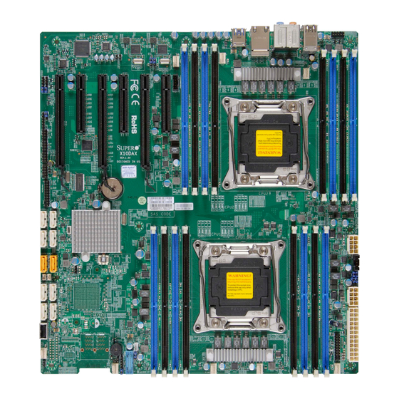
The following items are included in the retail box: • One (1) Supermicro Mainboard • Six (6) Serial ATA cables (CBL-0044Lx6) (X10DAi/X10DAX Only) • Two (2) Serial ATA cables (CBL-0044Lx2) (X10DAC Only) • Two (2) SAS cable (CBL-SAST-0532x2) (X10DAC Only) •... - Page 10 X10DAi/X10DAC/X10DAX Motherboard User's Manual Motherboard Image Note: All graphics shown in this manual were based upon the latest PCB Revision available at the time of publishing of the manual. The motherboard you've received may or may not look exactly the same as the graphics...
-
Page 11: Motherboard Layout
Audio CTRL AUDIO_FP LAN CTRL LAN CTRL FAN4 JAUDIO1 USB0/1 CPU2 CLOSE 1st BIOS OPEN 1st LICENSE Battery Battery X10DAi/DAC/DAX MAC CODE BAR CODE Rev. 1.01 SAS CODE CPU1 JBT1 CLOSE 1st BIOS CTRL OPEN 1st SAS4~7 SAS0~3 JSTBY1 JWD1... - Page 12 X10DAi/X10DAC/X10DAX Motherboard User's Manual X10DAi/X10DAC/X10DAX Quick Reference USB7/8(3.0) USB5/6(3.0) LAN1/2 Audio CTRL AUDIO_FP LAN CTRL LAN CTRL FAN4 JAUDIO1 USB0/1 CPU2 CLOSE 1st BIOS OPEN 1st LICENSE Battery Battery X10DAi/DAC/DAX MAC CODE BAR CODE Rev. 1.01 SAS CODE CPU1 JBT1...
-
Page 13: Jumper Description
Chapter 1: Overview X10DAi/X10DAC/X10DAX Jumpers Jumper Description Default Setting JBT1 Clear CMOS See Chapter 2 C1/JI SMBus to PCI-E Slots Pins 2-3 (Normal) JPL1 GLAN1 & GLAN2 Enable/Disable Pins 1-2 (Enabled) JPL2 GLAN2 Enable/Disable Pins 1-2 (Enabled) JPME2 ME (Manufacture) Mode Select... - Page 14 X10DAi/X10DAC/X10DAX Motherboard User's Manual I-SATA0-9 Serial_Link ATA Connections 0-9 supported by Intel PCH (I-SATA4/5 support Supermicro SuperDOMs [Devices-on-Module] with power pins built-in) SAS 0-3, 4-7 (JS2) Serial_Link SCSI Connections 0-3, 4-7 supported by LSI SAS Control- (X10DAC Only) Onboard Buzzer (Internal Speaker)
-
Page 15: Motherboard Features
Chapter 1: Overview Motherboard Features • Dual Intel E5-2600v3 Series Processors (Socket R ® LGA 2011); each processor supports two full-width Intel QuickPath Interconnect (QPI) links (with support of up to 9.6 GT/s per QPI link). • Memory Integrated memory controller supports up to 1024 GB of Load Reduced (LRDIMM) or up to 512 GB of Registered (RDIMM) ECC DDR4 2133/1866/1600 MHz memory modules in 16 DIMM slots. -
Page 16: Peripheral Devices
X10DAi/X10DAC/X10DAX Motherboard User's Manual Peripheral USB Devices Devices • Four (4) rear USB 3.0 ports (USB 3.0 ports 5/6, 7/8), • Two (2) rear USB 2.0 ports (USB 2.0 ports 0/1) • Two (2) USB 3.0 connections for front access (USB 9/10) •... - Page 17 Chapter 1: Overview System- CPU Monitoring Health • Monitoring Onboard voltage monitors for +1.05V, 1.5V, +3.3V, 3.3VSB, +5V, +5V Standby, +12V, chipset, memory, CPU1/2 vcores, and battery voltages. • CPU/System overheat LED and control • CPU Thermal Trip support • Thermal Monitor 2 (TM2) support Fan Control •...
-
Page 18: System Block Diagram
X10DAi/X10DAC/X10DAX Motherboard User's Manual 9.6G DDR-IV DDR-IV DMI2 DMI2 9.6G SLOT1 PCI-E X16 G3 PCI-E X16 G3 PCI-E X16 G3 SLOT3 PCI-E X8 G3 PCI-E X8 G3 LSI 3008 SLOT 5 PCI-E X8 G3 DMI2 4GB/s SLOT 4 SLOT 2... -
Page 19: Processor And Chipset Overview
Processor and Chipset Overview Built upon the functionality and the capability of the Intel E5-2600v3 Series Proces- sors (Socket R v3 LGA 2011) and the C612 chipset, the X10DAi/DAC/DAX moth- erboard provides the performance and feature sets required for dual_processor- based workstation platforms. -
Page 20: Special Features
X10DAi/X10DAC/X10DAX Motherboard User's Manual Special Features Recovery from AC Power Loss The Basic I/O System (BIOS) provides a setting that determines how the system will respond when AC power is lost and then restored to the system. You can choose for the system to remain powered off (in which case you must press the power switch to turn it back on), or for it to automatically return to the power-on state. -
Page 21: Acpi Features
It is even more important for processors that have high CPU clock rates. The X10DAi/DAC/DAX motherboard accommodates 24-pin ATX power supplies. Although most power supplies generally meet the specifications required by the CPU, some are inadequate. In addition, two 8-pin power connections are also required to ensure adequate power supply to the system. - Page 22 X10DAi/X10DAC/X10DAX Motherboard User's Manual Notes 1-14...
-
Page 23: Chapter 2 Installation
Chapter 2: Installation Chapter 2 Installation Standardized Warning Statements The following statements are industry-standard warnings, provided to warn the user of situations which have the potential for bodily injury. Should you have questions or experience difficulty, contact Supermicro's Technical Support department for assis- tance. - Page 24 X10DAi/X10DAC/X10DAX Motherboard User's Manual Attention Danger d'explosion si la pile n'est pas remplacée correctement. Ne la remplacer que par une pile de type semblable ou équivalent, recommandée par le fabricant. Jeter les piles usagées conformément aux instructions du fabricant. ¡Advertencia! Existe peligro de explosión si la batería se reemplaza de manera incorrecta.
-
Page 25: Product Disposal
Chapter 2: Installation Product Disposal Warning! Ultimate disposal of this product should be handled according to all national laws and regulations. 製品の廃棄 この製品を廃棄処分する場合、 国の関係する全ての法律 ・ 条例に従い処理する必要が あります。 警告 本产品的废弃处理应根据所有国家的法律和规章进行。 警告 本產品的廢棄處理應根據所有國家的法律和規章進行。 Warnung Die Entsorgung dieses Produkts sollte gemäß allen Bestimmungen und Gesetzen des Landes erfolgen. -
Page 26: Static-Sensitive Devices
X10DAi/X10DAC/X10DAX Motherboard User's Manual 경고! 이 제품은 해당 국가의 관련 법규 및 규정에 따라 폐기되어야 합니다. Waarschuwing De uiteindelijke verwijdering van dit product dient te geschieden in overeenstemming met alle nationale wetten en reglementen. Static-Sensitive Devices Electrostatic Discharge (ESD) can damage electronic com ponents. To avoid dam- aging your system board, it is important to handle it very carefully. -
Page 27: Motherboard Installation
Standoffs (9 pieces, if needed) Location of Mounting Holes There are nine (9) mounting holes on this motherboard indicated by the arrows. BIOS LICENSE X10DAi/DAC/DAX MAC CODE BAR CODE Rev. 1.01 SAS CODE Warning: 1) To avoid damaging the motherboard and its components, please do not use a force greater than 8 lb/inch on each mounting screw during motherboard installation. -
Page 28: Installing The Motherboard
X10DAi/X10DAC/X10DAX Motherboard User's Manual Installing the Motherboard Note: Always connect the power cord last, and always remove it before adding, removing or changing any hardware components. 1. Install the I/O shield into the chassis. 2. Locate the mounting holes on the motherboard. -
Page 29: Processor And Heatsink Installation
Chapter 2: Installation Processor and Heatsink Installation Warning: When handling the processor package, avoid placing direct pressure on the label area. Also, improper CPU installation or socket/pin misalignment can cause serious damage to the CPU or the motherboard that will require RMA repairs. Be sure to read and follow all instructions thoroughly before installing your CPU and heatsink. - Page 30 X10DAi/X10DAC/X10DAX Motherboard User's Manual 2. Press the second load lever labeled "Close 1st" to release the load plate that covers the CPU socket from its locking position. Pull lever away from Press down on load socket lever "Close 1st" 3. With the lever labeled "Close 1st" fully retracted, gently push down on the lever labeled "Open 1st"...
- Page 31 Chapter 2: Installation 4. Use your thumb and index finger to loosen the lever and open the load plate. 5. Using your thumb and index finger, hold the CPU by its edges. Align the CPU keys, which are semicircle notches, against the socket keys. Socket Keys CPU Keys 6.
- Page 32 X10DAi/X10DAC/X10DAX Motherboard User's Manual 7. With the CPU inside the socket, inspect the four corners of the CPU to make sure that the CPU is properly installed. Gently close Push down and lock the the load plate lever labeled "Close 1st"...
-
Page 33: Installing A Passive Cpu Heatsink
Chapter 2: Installation Installing a Passive CPU Heatsink 1. Do not apply any thermal grease to the heatsink or the CPU die -- the re- quired amount has already been applied. 2. Place the heatsink on top of the CPU so that the four mounting holes are aligned with those on the motherboard's and the heatsink bracket underneath. -
Page 34: Removing The Heatsink
X10DAi/X10DAC/X10DAX Motherboard User's Manual Removing the Heatsink Warning: We do not recommend that the CPU or the heatsink be removed. However, if you do need to uninstall the heatsink, please follow the instructions below to uninstall the heatsink to prevent damage done to the CPU or the CPU socket. -
Page 35: Installing And Removing The Memory Modules
P1-DIMMA1. (For best performance, please use the memory modules of the same type and the same speed.) 2. Push the release tabs outwards on both ends of the DIMM slot to unlock it. Notches BIOS LICENSE X10DAi/DAC/DAX MAC CODE BAR CODE Rev. 1.01 SAS CODE Release Tabs 3. - Page 36 X10DAi/X10DAC/X10DAX Motherboard User's Manual Memory Support for the X9DAi Motherboard This motherboard supports up to 1024 GB of Load Reduced (LRDIMM) or up to 512 GB of Registered (RDIMM) ECC DDR4 2133/1866/1600 MHz memory modules in 16 DIMM slots. Note1: Memory speed support is pending on the CPUs installed on the motherboard.
- Page 37 Chapter 2: Installation Populating RDIMM/LRDIMM ECC Memory Modules Speed (MT/s), Slot per Channel (SPC) & DIMM per Channel (DPC) 2-15...
-
Page 38: Control Panel Connectors And I/O Ports
X10DAi/X10DAC/X10DAX Motherboard User's Manual Control Panel Connectors and I/O Ports The I/O ports are color coded in conformance with the industry standards. See the picture below for the colors and locations of the various I/O ports. Back Panel Connectors and I/O Ports... -
Page 39: Ethernet Ports
Link 100 LED (Yel- LAN LED information.) low, +3V3SB) TD1- Link 1000 LED (Yellow, +3V3SB) TD2+ Ground TD2- Ground TD3+ Ground TD3- Ground (NC: No Connection) 1. LAN1 2. LAN2 BIOS LICENSE X10DAi/DAC/DAX MAC CODE BAR CODE Rev. 1.01 SAS CODE 2-17... -
Page 40: Universal Serial Bus (Usb)
X10DAi/X10DAC/X10DAX Motherboard User's Manual Universal Serial Bus (USB) Six Universal Serial Bus (USB) ports are located on the I/O back panel. Rear USB ports 5/6 and USB 7/8 support 3.0 connections, while USB ports 0/1 support 2.0 connections. Two USB headers provide four USB connections (USB 2/3, 9/10) for front access. -
Page 41: 7.1 Hd (High-Definition) Audio
See the tables above for pin definitions for onboard audio headers. 1.SPDIF_Out 2. Surround_Out 3. CEN/LFE_Out 4. Mic_In 5. Line-Out 6. Line_In 7. Audio Header BIOS LICENSE X10DAi/DAC/DAX MAC CODE BAR CODE Rev. 1.01 SAS CODE 2-19... -
Page 42: Front Control Panel
X10DAi/X10DAC/X10DAX Motherboard User's Manual Front Control Panel JF1 contains header pins for various buttons and indicators that are normally lo- cated on a control panel at the front of the chassis. These connectors are designed specifically for use with Supermicro's server chassis. See the figure below for the descriptions of the various control panel buttons and LED indicators. -
Page 43: Front Control Panel Pin Definitions
JAUDIO1 USB0/1 B. PWR LED CPU2 CLOSE 1st Ground BIOS OPEN 1st LICENSE Power LED Battery Battery X10DAi/DAC/DAX MAC CODE HDD LED BAR CODE Rev. 1.01 SAS CODE NIC1 LED CPU1 JBT1 NIC2 LED CLOSE 1st BIOS OH/Fan Fail LED... -
Page 44: Hdd Led
X10DAi/X10DAC/X10DAX Motherboard User's Manual HDD LED HDD LED Pin Definitions (JF1) The HDD LED connection is located Pin# Definition on pins 13 and 14 of JF1. Attach a 3.3V Standby cable here to indicate HDD activ- HD Active ity. See the table on the right for pin definitions. -
Page 45: Overheat (Oh)/Fan Fail Led
USB0/1 Ground CPU2 CLOSE 1st Power LED BIOS HDD LED OPEN 1st LICENSE Battery Battery NIC1 LED X10DAi/DAC/DAX MAC CODE BAR CODE Rev. 1.01 SAS CODE NIC2 LED CPU1 OH/Fan Fail LED JBT1 CLOSE 1st BIOS PWR Fail LED Reset... -
Page 46: Reset Button
X10DAi/X10DAC/X10DAX Motherboard User's Manual Reset Button Reset Button Pin Definitions (JF1) The Reset Button connection is located Pin# Definition on pins 3 and 4 of JF1. Attach it to a Reset hardware reset switch on the computer Ground case. Refer to the table on the right for pin definitions. -
Page 47: Connecting Cables
B. JPWR1: 8-pin Proces- sor PWR (Req'd) CPU2 C. JPWR2: 8-pin Proces- CLOSE 1st sor PWR (Req'd) BIOS OPEN 1st LICENSE Battery Battery X10DAi/DAC/DAX MAC CODE BAR CODE Rev. 1.01 SAS CODE CPU1 JBT1 CLOSE 1st BIOS CTRL OPEN 1st... -
Page 48: Fan Headers
X10DAi/X10DAC/X10DAX Motherboard User's Manual Fan Headers Fan Header Pin Definitions This motherboard has eight system/CPU Pin# Definition fan headers (Fan 1~Fan 7, and Fan A) Ground on the motherboard. All these 4-pin fans +12V headers are backward compatible with Tachometer the traditional 3-pin fans. -
Page 49: Internal Speaker
LAN CTRL A. Internal Speaker FAN4 JAUDIO1 USB0/1 (Buzzer) B. PWR LED/Speaker CPU2 CLOSE 1st BIOS OPEN 1st LICENSE Battery Battery X10DAi/DAC/DAX MAC CODE BAR CODE Rev. 1.01 SAS CODE CPU1 JBT1 CLOSE 1st BIOS CTRL OPEN 1st SAS4~7 SAS0~3 JSTBY1... -
Page 50: Tpm Header/Port 80 Header
X10DAi/X10DAC/X10DAX Motherboard User's Manual TPM Header/Port 80 Header TPM/Port 80 Header Pin Definitions A Trusted Platform Module/Port 80 Pin # Definition Pin # Definition header is located at JTPM1 to provide LCLK TPM support and Port 80 connection. LFRAME# <(KEY)>... -
Page 51: Power Smb (I 2 C) Connector
Audio CTRL AUDIO_FP LAN CTRL LAN CTRL FAN4 JAUDIO1 USB0/1 CPU2 CLOSE 1st BIOS OPEN 1st LICENSE Battery Battery X10DAi/DAC/DAX MAC CODE BAR CODE Rev. 1.01 SAS CODE CPU1 JBT1 CLOSE 1st BIOS CTRL OPEN 1st SAS4~7 SAS0~3 JSTBY1 JWD1... -
Page 52: T-Sgpio 1/2/3 Headers
X10DAi/X10DAC/X10DAX Motherboard User's Manual T-SGPIO 1/2/3 Headers T-SGPIO Pin Definitions Two SGPIO (Serial-Link General Pin# Definition Definition Purpose Input/Output) headers are located on the motherboard. These Ground Data headers support Serial_Link interface Load Ground for onboard SATA/SAS connections Clock when available. See the table on the Note: NC= No Connection right for pin definitions. -
Page 53: Spdif_In/Spdif_Out Headers
AUDIO_FP LAN CTRL LAN CTRL B. SPDIF_Out FAN4 JAUDIO1 USB0/1 CPU2 CLOSE 1st BIOS OPEN 1st LICENSE Battery Battery X10DAi/DAC/DAX MAC CODE BAR CODE Rev. 1.01 SAS CODE CPU1 JBT1 CLOSE 1st BIOS CTRL OPEN 1st SAS4~7 SAS0~3 JSTBY1 JWD1... -
Page 54: Jumper Settings
X10DAi/X10DAC/X10DAX Motherboard User's Manual Jumper Settings Explanation of Jumpers Connector Pins To modify the operation of the mother- board, jumpers can be used to choose between optional settings. Jumpers Jumper create shorts between two pins to change the function of the connector. -
Page 55: Cmos Clear
LAN CTRL LAN CTRL B. Watch Dog Enable FAN4 JAUDIO1 USB0/1 CPU2 CLOSE 1st BIOS OPEN 1st LICENSE Battery Battery X10DAi/DAC/DAX MAC CODE BAR CODE Rev. 1.01 SAS CODE CPU1 JBT1 CLOSE 1st BIOS CTRL OPEN 1st SAS4~7 SAS0~3 JSTBY1... -
Page 56: Manufacturer Mode Select
X10DAi/X10DAC/X10DAX Motherboard User's Manual Manufacturer Mode Select ME Mode Select Jumper Settings Close this jumper (JPME2) to bypass Jumper Setting Definition SPI flash security and force the system Manufacture Mode (Default) to use the Manufacturer mode which Disabled will allow the user to flash the system firmware from a host server to modify system settings. -
Page 57: Onboard Led Indicators
AUDIO_FP LAN CTRL LAN CTRL B. Onboard PWR FAN4 JAUDIO1 USB0/1 CPU2 CLOSE 1st BIOS OPEN 1st LICENSE Battery Battery X10DAi/DAC/DAX MAC CODE BAR CODE Rev. 1.01 SAS CODE CPU1 JBT1 CLOSE 1st BIOS CTRL OPEN 1st SAS4~7 SAS0~3 JSTBY1... -
Page 58: Sas Heartbeat Led (X10Dac Only)
X10DAi/X10DAC/X10DAX Motherboard User's Manual SAS Heartbeat LED (X10DAC Only) SAS Heartbeat LED Status (DS1) A SAS Heartbeat LED is Located at DS1 Color/State Definition on the motherboard. See the table at right Green: SAS Active for more information. Blinking Red: Solid On SAS Error USB7/8(3.0) -
Page 59: 2-10 Sata/Sas Connections
CLOSE 1st G. I-SATA6 H. I-SATA7 I. I-SATA8 BIOS OPEN 1st LICENSE J. I-SATA9 Battery Battery K. SAS 0-3 X10DAi/DAC/DAX MAC CODE BAR CODE Rev. 1.01 SAS CODE (X10DAC Only) L. SAS 4-7 CPU1 JBT1 (X10DAC Only) CLOSE 1st BIOS... - Page 60 X10DAi/X10DAC/X10DAX Motherboard User's Manual Notes 2-38...
-
Page 61: Chapter 3 Troubleshooting
Chapter 3: Troubleshooting Chapter 3 Troubleshooting Troubleshooting Procedures Use the following procedures to troubleshoot your system. If you have followed all of the procedures below and still need assistance, refer to the ‘Technical Support Procedures’ and/or ‘Returning Merchandise for Service’ section(s) in this chapter. Note: Always disconnect the power cord before adding, changing or installing any hardware components. -
Page 62: System Boot Failure
X10DAi/X10DAC/X10DAX Motherboard User's Manual No Video 1. If the power is on, but you have no video, remove all the add-on cards and cables. 2. Use the speaker to determine if any beep codes exist. Refer to Appendix A for details on beep codes. -
Page 63: Memory Errors
Chapter 3: Troubleshooting Memory Errors When a No-Memory Beep Code is issued by the system, check the following: 1. Make sure that the memory modules are compatible with the system and that the DIMM modules are properly and fully installed. (For memory compatibility, refer to the Memory Compatibility Chart posted on our Website @ http://www. - Page 64 X10DAi/X10DAC/X10DAX Motherboard User's Manual within the normal range. Also check the front panel Overheat LED, and make sure that the Overheat LED is not on. 5. Adequate power supply: Make sure that the power supply provides adequate power to the system. Make sure that all power connectors are connected.
-
Page 65: Technical Support Procedures
Chapter 3: Troubleshooting Technical Support Procedures Before contacting Technical Support, please take the following steps. Also, please note that as a motherboard manufacturer, Supermicro also sells motherboards through its channels, so it is best to first check with your distributor or reseller for troubleshooting services. -
Page 66: Battery Removal And Installation
X10DAi/X10DAC/X10DAX Motherboard User's Manual Battery Removal and Installation Battery Removal To remove the onboard battery, follow the steps below: 1. Power off your system and unplug your power cable. 2. Locate the onboard battery as shown below. 3. Using a tool such as a pen or a small screwdriver, push the battery lock out- wards to unlock it. -
Page 67: Frequently Asked Questions
Chapter 3: Troubleshooting Frequently Asked Questions Question: What are the various types of memory that my motherboard can support? Answer: The motherboard supports Registered (RDIMM)/Load Reduced (LRDIMM) ECC DDR4 2133/1866/1600 MHz DIMM modules. To enhance memory perfor- mance, do not mix memory modules of different speeds and sizes. Please follow all memory installation instructions given on Section 2-4 in Chapter 2. -
Page 68: Returning Merchandise For Service
X10DAi/X10DAC/X10DAX Motherboard User's Manual Returning Merchandise for Service A receipt or copy of your invoice marked with the date of purchase is required before any warranty service will be rendered. You can obtain service by calling your ven- dor for a Returned Merchandise Authorization (RMA) number. When returning the... -
Page 69: Chapter 4 Bios
BIOS Introduction This chapter describes the AMI BIOS setup utility for the X10DAi/X10DAC/X10DAX. The ROM BIOS is stored in a Flash EEPROM and can be easily updated. This chapter describes the basic navigation of the AMI BIOS setup utility screens. -
Page 70: Main Setup
X10DAi/X10DAC/X10DAX Motherboard User’s Manual How to Start the Setup Utility Normally, the only visible Power-On Self-Test (POST) routine is the memory test. As the memory is being tested, press the <Delete> key to enter the main menu of the AMI BIOS setup utility. From the main menu, you can access the other setup screens. - Page 71 Note: The time is in the 24-hour format. For example, 5:30 P.M. appears as 17:30:00. Supermicro X10DAi/C Version: This item displays the version of the BIOS ROM used in the system. Build Date: This item displays the date when the version of the BIOS ROM used in the system was built.
-
Page 72: Advanced Setup Configurations
X10DAi/X10DAC/X10DAX Motherboard User’s Manual Advanced Setup Configurations Use the arrow keys to select Advanced setup and press <Enter> to access the submenu items: CPU Configuration Chipset Configuration SATA Configuration sSATA Configuration PCIe/PCI/PnP Configuration ACPI Settings NCT7904D HW Monitor Intel (R) Thunderbolt Warning: Take Caution when changing the Advanced settings. -
Page 73: Power Configuration
Chapter 4: AMI BIOS Wait For 'F1' If Error Select Enabled to force the system to wait until the 'F1' key is pressed if an error occurs. The options are Disabled and Enabled. INT19 (Interrupt 19) Trap Response Interrupt 19 is the software interrupt that handles the boot disk function. When this item is set to Immediate, the ROM BIOS of the host adaptors will "capture"... -
Page 74: Cpu Configuration
X10DAi/X10DAC/X10DAX Motherboard User’s Manual CPU Configuration This submenu displays the following CPU information as detected by the BIOS. It also allows the user to configure CPU settings. • Processor Socket • Processor ID • Processor Frequency • Processor Max Ratio •... - Page 75 Chapter 4: AMI BIOS codes to overwhelm the processor to damage the system during an attack. This feature is used in conjunction with the items: "Clear MCA," "VMX," "Enable SMX," and "Lock Chipset" for Virtualization media support. The options are Enable and Disable.
-
Page 76: Advanced Power Management Configuration
X10DAi/X10DAC/X10DAX Motherboard User’s Manual AES-NI Select Enable to use the Intel Advanced Encryption Standard (AES) New Instruc- tions (NI) to ensure data security. The options are Enable and Disable. Intel Virtualization Technology Select Enable to use Intel Virtualization Technology support for Direct I/O VT-d sup- port by reporting the I/O device assignments to the VMM (Virtual Machine Monitor) through the DMAR ACPI tables. - Page 77 Chapter 4: AMI BIOS CPU C State Control (Available when Power Technology is set to Custom) Package C State limit Use this item to set the limit on the C-State package register. The options are C0/1 state, C2 state, C6 (non-Retention) state, C6 (Retention) state, and No Limit.
-
Page 78: Chipset Configuration
X10DAi/X10DAC/X10DAX Motherboard User’s Manual Chipset Configuration Warning! Please set the correct settings for the items below. A wrong configuration setting may cause the system to malfunction. North Bridge This feature allows the user to configure the settings for the Intel North Bridge. -
Page 79: Intel Vt For Directed I/O
Chapter 4: AMI BIOS IIO2 Port 2A Link Speed Use this item to configure the link speed of a PCI-E device installed on the PCI- E slot specified by the user. The options are Gen1 (2.5 GT/s), Gen2 (5 GT/s), Gen3 (8 GT/s), and Auto. - Page 80 X10DAi/X10DAC/X10DAX Motherboard User’s Manual Coherency Support (Non-Isoch) Select Enable for the Non-Iscoh VT-d engine to pass through DMA (Direct Memo- ry Access) to enhance system performance. The options are Enable and Disable. Coherency Support (Isoch) Select Enable for the Iscoh VT-d engine to pass through ATS to enhance system performance.
-
Page 81: Memory Configuration
Chapter 4: AMI BIOS Isoc Mode Select Enable for Isochronous support to meet QoS (Quality of Service) require- ments. This feature is especially important for Virtualization Technology. The options are Enable and Disable. Memory Configuration Enforce POR Select Enabled to enforce POR restrictions on memory frequency and voltage programming. -
Page 82: Dimm Information
X10DAi/X10DAC/X10DAX Motherboard User’s Manual DIMM Information This item displays the status of a DIMM module as detected by the BIOS. P1-DIMMA1/A2, P1-DIMMB1/B2, P1-DIMMC1/C2, P1-DIMMD1/D2, P2- DIMME1/E2, P2-DIMMF1/F2, P2-DIMMG1/G2, and P2-DIMMH1/H2 Memory RAS (Reliability_Availability_Serviceability) Configuration Use this submenu to configure the following Memory RAS settings. -
Page 83: South Bridge Configuration
Chapter 4: AMI BIOS Device Tagging Select Enable to support device tagging. The options are Disable and Enable. South Bridge Configuration The following South Bridge information will display: USB Configuration • USB Module Version • USB Devices Legacy USB Support Select Enabled to support onboard legacy USB devices. - Page 84 X10DAi/X10DAC/X10DAX Motherboard User’s Manual EHCI2 Select Enabled to enable EHCI (Enhanced Host Controller Interface) support on USB 2.0 connector #2 (-at least one USB 2.0 connector should be enabled for EHCI support.) The options are Disabled and Enabled. Azalia Select Enabled to enable onboard Azalia audio devices. Select Auto for the BOIS to automatically enable Azalia support when an onboard Azalia device is detected.
-
Page 85: Sata Configuration
Chapter 4: AMI BIOS SATA Configuration When this submenu is selected, AMI BIOS automatically detects the presence of the SATA devices that are supported by the Intel PCH chip and displays the fol- lowing items: SATA Controller This item enables or disables the onboard SATA controller supported by the Intel PCH chip. - Page 86 X10DAi/X10DAC/X10DAX Motherboard User’s Manual *If the item above "Configure SATA as" is set to IDE, the following items will display: Serial ATA Port 0~ Port 5 This item indicates that a SATA port specified by the user is installed (present) or not.
-
Page 87: Ssata Configuration
Chapter 4: AMI BIOS Port 0 ~ Port 5 Spin Up Device On an edge detect from 0 to 1, set this item to allow the PCH to start a COMRE- SET initialization to the device. The options are Enabled and Disabled. Port 0 ~ Port 5 SATA Device Type Use this item to specify if the SATA port specified by the user should be con- nected to a Solid State drive or a Hard Disk Drive. - Page 88 X10DAi/X10DAC/X10DAX Motherboard User’s Manual sSATA Port 0 ~ Port 3 Spin Up Device On an edge detect from 0 to 1, set this item to allow the PCH to start a COMRE- SET initialization to the device. The options are Enabled and Disabled.
- Page 89 Chapter 4: AMI BIOS • Model number of drive and capacity • Software Preserve Support sSATA Port 0~ Port 3 Select Enabled to enable an sSATA port specified by the user. The options are Disabled and Enabled. sSATA Port 0 ~ Port 3 Spin Up Device On an edge detect from 0 to 1, set this item to allow the PCH to start a COMRE- SET initialization to the device.
- Page 90 X10DAi/X10DAC/X10DAX Motherboard User’s Manual PCIe/PCI/PnP Configuration PCI Devices Common Settings PCI Latency Timer Use this item to configure the PCI latency timer for a device installed on a PCI bus. Select 32 to set the PCI latency timer to 32 PCI clock cycles. The options are 32, 64, 96, 128, 160, 192, 224 and 248 (PCI Bus Clocks).
- Page 91 Chapter 4: AMI BIOS Maximum Read Request Select Auto for the system BIOS to automatically set the maximum size for a read request for a PCI-E device to enhance system performance. The options are Auto, 128 Bytes, 256 Bytes, 512 Bytes, 1024 Bytes, 2048 Bytes, and 4096 Bytes. ASPM Support Use this item to set the Active State Power Management (ASPM) level for a PCI-E device.
-
Page 92: Acpi Settings
X10DAi/X10DAC/X10DAX Motherboard User’s Manual Network Stack Select Enabled to enable PXE (Preboot Execution Environment) or UEFI (Uni- fied Extensible Firmware Interface) for network stack support. The options are Enabled and Disabled. Trusted Computing (Available when a TPM device is installed and detected by the BIOS) - Page 93 Chapter 4: AMI BIOS synchronizing multimedia streams, providing smooth playback and reducing the de- pendency on other timestamp calculation devices, such as an x86 RDTSC Instruc- tion embedded in the CPU. The High Performance Event Timer is used to replace the 8254 Programmable Interval Timer.
- Page 94 X10DAi/X10DAC/X10DAX Motherboard User’s Manual • CPU1 VCore/CPU2 VCore • VDIMM AB/VDIMM CD/VDIMM EF/VDIMM GH • 3.3V • 3.3VSB • VBAT Intel® Thunderbolt This feature is used to enable hot-plug support in the BIOS setup when the OS does not support PCI-E or SHPC hot-plugging.
- Page 95 Chapter 4: AMI BIOS Thunderbolt PCIe Cache-line Size Use this item to set the PCI-E cache-line size to be used in THE Thunderbolt sub- tree. The options are 0, 1, 2, 4, 8, 16, 32, 64 and 128. SMI/Notify Support If this item is set to Enabled, SMI (Structure of Management Information) notifica- tion will be provided for Thunderbolt Technology support.
-
Page 96: Event Logs
X10DAi/X10DAC/X10DAX Motherboard User’s Manual Event Logs Use this feature to configure Event Log settings. Change SMBIOS Event Log Settings This feature allows the user to configure SMBIOS Event settings. Enabling/Disabling Options SMBIOS Event Log Select Enabled to enable SMBIOS (System Management BIOS) Event Logging during system boot. -
Page 97: View Smbios Event Log
Chapter 4: AMI BIOS Memory Correctable Error Threshold Use this item to enter the threshold value for correctable memory errors. The default setting is 10. Erasing Settings Erase Event Log Select Enabled to erase all error events in the SMBIOS (System Management BIOS) log before an event logging is initialized at bootup. -
Page 98: Security Settings
X10DAi/X10DAC/X10DAX Motherboard User’s Manual Security Settings This menu allows the user to configure the following security settings for the system. Administrator Password Use this feature to set the administrator password which is required before the user entering the BIOS setup utility. The length of the password should be from 3 characters to 20 characters long. -
Page 99: Boot Settings
Chapter 4: AMI BIOS Boot Settings Use this feature to configure Boot Settings: Boot Configuration Boot Mode Select Use this item to select the type of device to be used for system boot. The options are Legacy, UEFI, and Dual. Fixed Boot Order Priorities This option prioritizes the order of bootable devices from which the system will boot. - Page 100 X10DAi/X10DAC/X10DAX Motherboard User’s Manual • Dual Boot Order #9 • Dual Boot Order #10 • Dual Boot Order #11 • Dual Boot Order #12 • Dual Boot Order #13 • Dual Boot Order #14 • Dual Boot Order #15 Add New Boot Option Use this item to select a new boot device to add to the boot priority list.
- Page 101 Chapter 4: AMI BIOS UEFI Application Boot Priorities • UEFI Boot Order #1 4-33...
-
Page 102: Save & Exit
X10DAi/X10DAC/X10DAX Motherboard User’s Manual Save & Exit Select the Save & Exit tab from the BIOS setup screen to configure the settings below. Discard Changes and Exit Select this option to quit the BIOS setup without making any permanent changes to the system configuration, and reboot the computer. - Page 103 Chapter 4: AMI BIOS Restore Optimized Defaults To set this feature, select Restore Optimized Defaults from the Exit menu and press <Enter>. These are manufacture default settings designed for maximum system performance but not for maximum stability. Save as User Defaults To set this feature, select Save as User Defaults from the Exit menu and press <En- ter>.
- Page 104 X10DAi/X10DAC/X10DAX Motherboard User’s Manual Notes 4-36...
-
Page 105: Appendix A Bios Error Beep Codes
Appendix A: BIOS POST Error Codes Appendix A BIOS Error Beep Codes During the POST (Power-On Self-Test) routines, which are performed at each system boot, errors may occur. Non-fatal errors are those which, in most cases, allow the system to continue to boot. - Page 106 X10DAi/X10DAC/X10DAX Motherboard User’s Manual Notes...
-
Page 107: Appendix B Software Installation Instructions
Appendix B: Software Installation Instructions Appendix B Software Installation Instructions B-1 Installing Software Programs After you've installed the operating system, a screen as shown below will appear. You are ready to install software programs and drivers that have not yet been in- stalled. -
Page 108: Configuring Superdoctor® 5
X10DAi/X10DAC/X10DAX Motherboard User's Manual B-2 Configuring SuperDoctor® 5 The Supermicro SuperDoctor 5 is a hardware monitoring program that functions in a command-line or web-based interface in Windows and Linux operating systems. The program monitors system health information such as CPU temperature, system voltages, system power consumption, fan speed, and provides alerts via email or Simple Network Management Protocol (SNMP). -
Page 109: Appendix C Uefi Bios Recovery Instructions
Appendix C: UEFI BIOS Recovery Appendix C UEFI BIOS Recovery Instructions Warning: Do not upgrade the BIOS unless your system has a BIOS-related issue. Flashing the wrong BIOS can cause irreparable damage to the system. In no event shall Supermicro be liable for direct, indirect, special, incidental, or consequential damages arising from a BIOS update. - Page 110 X10DAi/X10DAC/X10DAX User’s Manual 1. Using a different machine, copy the "Super.ROM" binary image file into the disc Root "\" Directory of a USB device or a writeable CD/DVD. Note: If you cannot locate the "Super.ROM" file in your driver disk, visit our website at www.supermicro.com to download the BIOS image into...
- Page 111 Appendix C: UEFI BIOS Recovery 6. After the process of BIOS Recovery is complete, press any key to reboot the system. 7. Using a different system, extract the BIOS package into a bootable USB flash drive. 8. When a DOS prompt appears, enter AMI.BAT BIOSname.### at the prompt. Note: Do not interrupt this process until BIOS flashing is completed.
- Page 112 X10DAi/X10DAC/X10DAX User’s Manual 9. After seeing the message that BIOS update is completed, unplug the AC pow- er cable from the power supply to clear CMOS, and then plug the AC power cable in the power supply again to power on the system.
- Page 113 (Disclaimer Continued) The products sold by Supermicro are not intended for and will not be used in life support systems, medical equipment, nuclear facilities or systems, aircraft, aircraft devices, aircraft/emergency communication devices or other critical systems whose failure to perform be reasonably expected to result in significant injury or loss of life or catastrophic property damage.
Need help?
Do you have a question about the X10DAi and is the answer not in the manual?
Questions and answers