Table of Contents
Advertisement
Quick Links
Advertisement
Table of Contents

Related Manuals for Supero X10SL7-F


Summary of Contents for Supero X10SL7-F
- Page 1 X10SL7-F USER’S MANUAL Revision 1.0b...
- Page 2 This product, including software and docu- mentation, is the property of Supermicro and/or its licensors, and is supplied only under a license. Any use or reproduction of this product is not allowed, except as expressly permitted by the terms of said license.
-
Page 3: About This Motherboard
X10SL7-F motherboard. About This Motherboard X10SL7-F supports a single Intel® Xeon E3-1200 v3 or 4th Genera- tion Core i3 processor in an LGA 1150 (H3) socket. With the Intel® C222 Express chipset built in, the X10SL7-F motherboard supports Intel® Active Management Technology (iAMT), offering great system enhancement to high performance stor- age platforms. -
Page 4: Conventions Used In The Manual
X10SL7-F User’s Manual Conventions Used in the Manual: Special attention should be given to the following symbols for proper system instal- lation: Warning: Critical information given to prevent damage to the components or injury to yourself. Note: Additional Information provided for correct system setup. -
Page 5: Contacting Supermicro
Super Micro Computer, Inc. 980 Rock Ave. San Jose, CA 95131 U.S.A. Tel: +1 (408) 503-8000 Fax: +1 (408) 503-8008 Email: marketing@supermicro.com (General Information) support@supermicro.com (Technical Support) Web Site: www.supermicro.com Europe Address: Super Micro Computer B.V. Het Sterrenbeeld 28, 5215 ML... -
Page 6: Table Of Contents
X10SL7-F User’s Manual Table of Contents Preface Chapter 1 Introduction Overview ......................1-1 Chipset Overview ................... 1-9 Special Features ................... 1-10 PC Health Monitoring ..................1-10 ACPI Features ....................1-11 Power Supply ....................1-11 Super I/O ....................... 1-12 Chapter 2 Installation Standardized Warning Statements ..............2-1 Static-Sensitive Devices .................. - Page 7 Table of Contents HDD LED ....................2-21 NIC1/NIC2 LEDs ..................2-21 Overheat (OH)/Fan Fail/PWR Fail/UID LED ..........2-22 Power Fail LED ..................2-22 Reset Button ................... 2-23 Power Button ................... 2-23 Connecting Cables ..................2-24 ATX Main PWR & CPU PWR Connectors (JPW1 & JPW2) ....2-24 Fan Headers (Fan 1-Fan 4 &...
- Page 8 X10SL7-F User’s Manual Chapter 3 Troubleshooting Troubleshooting Procedures ................3-1 Technical Support Procedures ................ 3-3 Frequently Asked Questions ................3-4 Battery Removal and Installation ..............3-5 Returning Merchandise for Service..............3-6 Chapter 4 BIOS Introduction ...................... 4-1 Main Setup ...................... 4-2 Advanced Setup Configurations..............
-
Page 9: Chapter 1 Introduction
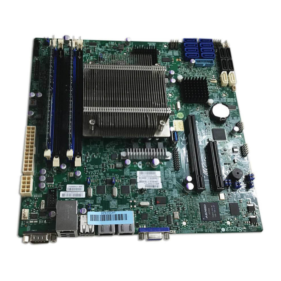
Checklist Congratulations on purchasing your computer motherboard from an acknowledged leader in the industry. Supermicro boards are designed with the utmost attention to detail to provide you with the highest standards in quality and performance. Please check that the following items have all been included with your motherboard. - Page 10 X10SL7-F User’s Manual X10SL7-F Motherboard Image Note: All graphics shown in this manual were based upon the latest PCB Revision available at the time of publishing of the manual. Your motherboard or components may or may not look exactly the same as the graphics shown in this manual.
- Page 11 Chapter 1: Introduction X10SL7-F Motherboard Layout USB2/3 COM1 USB4/5 COM2 LAN2 LAN1 IPMI _LAN CTRL CTRL IPMI CODE BAR CODE MAC CODE SAS CODE SPKR1 X10SL7-F Rev. 1.01 BIOS Battery JBT1 LEDS2 USB1 (3.0) CTRL JOH1 L-SAS6 L-SAS7 L-SAS4 L-SAS5...
- Page 12 X10SL7-F User’s Manual X10SL7-F Quick Reference USB2/3 COM1 USB4/5 COM2 LAN2 LAN1 IPMI _LAN CTRL CTRL IPMI CODE BAR CODE MAC CODE SAS CODE SPKR1 X10SL7-F Rev. 1.01 BIOS Battery JBT1 LEDS2 USB1 (3.0) CTRL JOH1 L-SAS6 L-SAS7 L-SAS4 L-SAS5...
- Page 13 USB 0,1 (3.0) USB 3.0 Ports 0, 1 (USB 0: Type A Connector) USB 8/9 Front Panel Accessible USB 2.0 Headers 8/9 Backpanel VGA Port X10SL7-F LED Indicators Description Status Standby Power LED On: Power On UID LED Blue (On): Unit Identified...
-
Page 14: Motherboard Features
X10SL7-F User’s Manual Motherboard Features Single Intel® Xeon E3-1200 v3 or 4th Generation Core i3 processor in an LGA1150 socket. Memory Four (4) SDRAM slots support up to 32 GB of DDR3 Unbuf- fered, ECC 1600/1333 MHz memory Dual-channel memory... - Page 15 Chapter 1: Introduction Power Configuration ACPI/APM Power Management Main Switch Override Mechanism Keyboard Wake-up from Soft-Off Power-on mode for AC power recovery PC Health Monitoring CPU Monitoring Onboard voltage monitors for CPU core, +3.3V, +5V,-12V, +12V, +3.3V Stdby, VBAT, Memory CPU 3-phase switching voltage regulator CPU/System overheat LED and control CPU Thermal Trip support...
-
Page 16: Block Diagram
X10SL7-F User’s Manual X10SL7-F Block Diagram BLOCK DIAGRAM RoHS 6/6 PCIe3.0_x8 DDR3 (CHA) DIMM1 Intel PCIe x16 SLOT DIMM2(Far) 8.0Gb 1600/1333MHz i3 Processor 4 UDIMM (H3) DDR3 (CHB) DIMM1 PCIe3.0_x8 DIMM2(Far) 1600/1333MHz LSI 2308 8.0Gb SAS2 6.0Gbps SVID 8 SAS PORTS VRM 12.5... -
Page 17: Chipset Overview
Chapter 1: Introduction Chipset Overview The X10SL7-F supports a Single Intel® Xeon E3-1200 v3 or 4th Generation Core i3 processor in an LGA1150 socket. Built upon the functionality and the capability of the C222 Express chipset, the motherboard provides substantial enhancement to system performance and storage capability for high performance platforms in a sleek package. -
Page 18: Special Features
X10SL7-F User’s Manual Special Features Recovery from AC Power Loss Basic I/O System (BIOS) provides a setting for you to determine how the system will respond when AC power is lost and then restored to the system. You can choose for the system to remain powered off, (in which case you must press the power switch to turn it back on), or for it to automatically return to a power-on state. -
Page 19: Acpi Features
Chapter 1: Introduction is used to notify the user of certain system events. For example, you can also configure SuperDoctor to provide you with warnings when the system temperature, CPU temperatures, voltages and fan speeds go beyond predefined thresholds. ACPI Features ACPI stands for Advanced Configuration and Power Interface. -
Page 20: Super I/O
X10SL7-F User’s Manual It is strongly recommended that you use a high quality power supply that meets ATX power supply Specification 2.02 or above. It must also be SSI compliant. (For more information, please refer to the web site at http://www.ssiforum.org/). Additionally, in areas where noisy power transmission is present, you may choose to install a line filter to shield the computer from noise. -
Page 21: Chapter 2 Installation
The following statements are industry-standard warnings, provided to warn the user of situations which have the potential for bodily injury. Should you have questions or experience difficulty, contact Supermicro's Technical Support department for assis- tance. Only certified technicians should attempt to install or configure components. - Page 22 X10SL7-F User’s Manual Attention Danger d'explosion si la pile n'est pas remplacée correctement. Ne la remplacer que par une pile de type semblable ou équivalent, recommandée par le fabricant. Jeter les piles usagées conformément aux instructions du fabricant. ¡Advertencia! Existe peligro de explosión si la batería se reemplaza de manera incorrecta. Re- emplazar la batería exclusivamente con el mismo tipo o el equivalente recomen-...
-
Page 23: Product Disposal
Chapter 2: Installation Product Disposal Warning! Ultimate disposal of this product should be handled according to all national laws and regulations. 製品の廃棄 この製品を廃棄処分する場合、 国の関係する全ての法律 ・ 条例に従い処理する必要が あり ます。 警告 本产品的废弃处理应根据所有国家的法律和规章进行。 警告 本產品的廢棄處理應根據所有國家的法律和規章進行。 Warnung Die Entsorgung dieses Produkts sollte gemäß allen Bestimmungen und Gesetzen des Landes erfolgen. -
Page 24: Static-Sensitive Devices
X10SL7-F User’s Manual 경고! 이 제품은 해당 국가의 관련 법규 및 규정에 따라 폐기되어야 합니다. Waarschuwing De uiteindelijke verwijdering van dit product dient te geschieden in overeenstemming met alle nationale wetten en reglementen. Static-Sensitive Devices Electrostatic-Discharge (ESD) can damage electronic com ponents. To avoid dam- aging your system board, it is important to handle it very carefully. -
Page 25: Processor And Heatsink Installation
CPU socket cap is in place and none of the socket pins are bent; otherwise, contact your retailer immediately. • Refer to the Supermicro website for updates on CPU support. Installing the LGA1150 Processor 1. Gently press down the load plate handle and push it outward (to the right side) to unlock it. - Page 26 X10SL7-F User’s Manual 3. Once the load plate is open, use your thumb and your index finger to hold the CPU at the north center edge and the south center edge of the CPU. North Center Edge South Center Edge 4.
- Page 27 Chapter 2: Installation 7. Once the CPU is properly installed, use your thumb to gently push the load plate handle down to the handle lock and lock it. CPU properly installed Load Plate Handle is locked into place 8. When the CPU is securely locked into the CPU socket, the plastic cap will be automatically loosened from the load plate.
-
Page 28: Installing A Passive Cpu Heatsink
X10SL7-F User’s Manual Installing a Passive CPU Heatsink 1. Do not apply thermal grease to the heatsink or the CPU die; the required amount has already been applied. 2. Place the heatsink on top of the CPU so that the four mounting holes are aligned with those on the motherboard and the underlying heatsink bracket. -
Page 29: Removing The Heatsink
Chapter 2: Installation Removing the Heatsink Warning: We do not recommend that the CPU or the heatsink be removed. However, if you do need to uninstall the heatsink, please follow the instructions below to remove the heatsink to avoid damaging the CPU or the CPU socket. 1. -
Page 30: Installing Ddr3 Memory
X10SL7-F User’s Manual Installing DDR3 Memory Note: Check the Supermicro website for recommended memory mod- ules. CAUTION Exercise extreme care when installing or removing DIMM modules to prevent any possible damage. DIMM Installation 1. Insert the desired number of DIMMs... -
Page 31: Removing Memory Modules
(Blue Slot) Towards the edge of the motherboard The X10SL7-F supports up to 32GB of Unbuffered (UDIMM) DDR3 ECC 1600/1333 MHz in 4 memory slots. Populating these DIMM modules with a pair of memory modules of the same type and same size will result in interleaved memory, which will improve memory performance. - Page 32 X10SL7-F User’s Manual • For Microsoft Windows users: Microsoft implemented a design change in the Windows XP with Service Pack 2 (SP2) and Windows Vista. This change is specific to the behavior of Physical Address Extension (PAE) mode which improves driver compatibility. For more information, please read the following article at Microsoft’s Knowledge Base website at: http://support.microsoft.
-
Page 33: Motherboard Installation
Standoffs (8) Philips Screws (8) Only if Needed Location of Mounting Holes X10SL7-F Rev. 1.01 Caution: 1) To avoid damaging the motherboard and its components, please do not use a force greater than 8 lb/inch on each mounting screw during motherboard installation. -
Page 34: Installing The Motherboard
X10SL7-F User’s Manual Installing the Motherboard 1. Install the I/O shield into the back of the chassis. 2. Locate the mounting holes on the motherboard. (See the previous page.) 3. Locate the matching mounting holes on the chassis. Align the mounting holes on the motherboard against the mounting holes on the chassis. -
Page 35: Connectors/Io Ports
Connectors/IO Ports The I/O ports are color coded in conformance with the PC 99 specification. See the figure below for the colors and locations of the various I/O ports. Backplane I/O Panel X10SL7-F Rev. 1.01 Backplane I/O Panel A. COM1 F. -
Page 36: Universal Serial Bus (Usb)
X10SL7-F User’s Manual Universal Serial Bus (USB) Four Universal Serial Bus 2.0 ports (2/3, 4/5) are located on the I/O back panel. In addition, one USB 2.0 header (two USB 2.0 connections: 8/9), and two USB 3.0 connectors (USB 0, USB 1) are also located on the motherboard to provide USB 3.0 support using USB cables (not included). -
Page 37: Ethernet Ports
COM2 C. IPIMI_LAN LAN2 LAN1 IPMI _LAN CTRL CTRL IPMI CODE D. COM1 BAR CODE MAC CODE SAS CODE E. COM2 SPKR1 X10SL7-F Rev. 1.01 BIOS Battery JBT1 LEDS2 USB1 (3.0) CTRL JOH1 L-SAS6 L-SAS7 L-SAS4 L-SAS5 L-SAS2 L-SAS3 L-SAS0... -
Page 38: Unit Identifier Switch/Uid Led Indicator
X10SL7-F User’s Manual Unit Identifier Switch/UID LED Indicator UID Switch A Unit Identifier (UID) switch and an LED Pin# Definition Indicator are located on the motherboard. Ground The UID switch is located next to the VGA Ground port on the backplane. The UID LED (LE4) Button In is located next to the UID switch. -
Page 39: Front Control Panel
These connectors are designed spe- cifically for use with Supermicro chassis. See the figure below for the descriptions of the front control panel buttons and LED indicators. Refer to the following section for descriptions and pin definitions. -
Page 40: Front Control Panel Pin Definitions
X10SL7-F User’s Manual Front Control Panel Pin Definitions NMI Button NMI Button Pin Definitions (JF1) The non-maskable interrupt button Pin# Definition header is located on pins 19 and 20 Control of JF1. Refer to the table on the right Ground for pin definitions. -
Page 41: Hdd Led
COM2 LAN2 LAN1 IPMI _LAN CTRL CTRL IPMI CODE BAR CODE Power LED MAC CODE SAS CODE SPKR1 X10SL7-F HDD LED Rev. 1.01 BIOS NIC1 LED Battery NIC2 LED OH/Fan Fail LED PWR Fail LED JBT1 LEDS2 USB1 (3.0) Reset... -
Page 42: Overheat (Oh)/Fan Fail/Pwr Fail/Uid Led
X10SL7-F User’s Manual Overheat (OH)/Fan Fail/PWR Fail/ OH/Fan Fail/ PWR Fail/Blue_UID UID LED LED Pin Definitions (JF1) Pin# Definition Connect an LED cable to pins 7 and 8 of Front Control Panel to use the Red_LED-Cathode/OH/Fan Fail/ Overheat, Fan Fail, and Power Fail Power Fail connections. -
Page 43: Reset Button
COM2 LAN2 LAN1 IPMI _LAN CTRL CTRL IPMI CODE BAR CODE MAC CODE Power LED SAS CODE SPKR1 X10SL7-F HDD LED Rev. 1.01 BIOS NIC1 LED Battery NIC2 LED OH/Fan Fail LED PWR Fail LED JBT1 LEDS2 USB1 (3.0) Reset... -
Page 44: Connecting Cables
X10SL7-F User’s Manual Connecting Cables This section provides brief descriptions and pin-out definitions for onboard headers and connectors. Be sure to use the correct cable for each header or connector. For information on Backpanel USB and Front Panel USB ports, refer to Page 2-17. -
Page 45: Fan Headers (Fan 1-Fan 4 & Fan A )
Chapter 2: Installation Fan Headers (Fan 1-Fan 4 & Fan A ) Fan Header Pin Definitions The X10SL7-F has five fan headers (Fan 1-Fan Pin# Definition 4 & Fan A). These fans are 4-pin fan headers. Ground (Black) Although pins 1-3 of the onboard fan headers 2.5A/+12V... -
Page 46: Internal Buzzer (Spkr1)
X10SL7-F User’s Manual Internal Buzzer (SPKR1) Internal Buzzer Pin Definition The Internal Buzzer (SPKR1) is used to Pin# Definitions provide audible indications for various Pin 1 Pos. (+) Beep In beep codes. See the table on the right Pin 2 Neg. -
Page 47: Dom Pwr Connector (Jsd1)
USB2/3 COM1 B. Standby PWR USB4/5 COM2 LAN2 LAN1 _LAN IPMI CTRL CTRL IPMI CODE BAR CODE MAC CODE SAS CODE SPKR1 X10SL7-F Rev. 1.01 BIOS Battery JBT1 LEDS2 USB1 (3.0) CTRL JOH1 L-SAS6 L-SAS7 L-SAS4 L-SAS5 L-SAS2 L-SAS3 L-SAS0... -
Page 48: T-Sgpio 1/2 & 6-Sgpio 1/2 Headers
X10SL7-F User’s Manual T-SGPIO 1/2 & 6-SGPIO 1/2 Headers T-SGPIO/6-SGPIO Pin Definitions Four Serial-Link General Purpose In- Pin# Definition Definition put/Output headers (T-SGPIO 1/2 & 6-SGPIO 1/2) are located on the moth- Data Ground erboard. T-SGPIO 1/2 support onboard Ground... -
Page 49: Tpm Header/Port 80 Header
USB2/3 A. TPM/Port 80 COM1 USB4/5 COM2 LAN2 LAN1 IPMI _LAN CTRL CTRL IPMI CODE BAR CODE MAC CODE SAS CODE SPKR1 X10SL7-F Rev. 1.01 BIOS Battery JBT1 LEDS2 USB1 (3.0) CTRL JOH1 L-SAS6 L-SAS7 L-SAS4 L-SAS5 L-SAS2 L-SAS3 L-SAS0... -
Page 50: Jumper Settings
X10SL7-F User’s Manual Jumper Settings Explanation of Jumpers To modify the operation of the mother- board, jumpers can be used to choose between optional settings. Jumpers create shorts between two pins to change the function of the connector. Pin 1 is identified with a square solder pad on the printed circuit board. -
Page 51: Cmos Clear (Jbt1)
COM1 B. JI USB4/5 COM2 C. JI LAN2 LAN1 IPMI _LAN CTRL CTRL IPMI CODE BAR CODE MAC CODE SAS CODE SPKR1 X10SL7-F Rev. 1.01 BIOS Battery JBT1 LEDS2 USB1 (3.0) CTRL JOH1 L-SAS6 L-SAS7 L-SAS4 L-SAS5 L-SAS2 L-SAS3 L-SAS0... -
Page 52: Me Recovery
X10SL7-F User’s Manual ME Recovery ME Recovery Jumper Settings Set Jumper JPME1 to select ME Firm- Jumper Setting Definition ware Recovery mode, which will limit Normal (Default) system resource for essential function ME Recovery use only without putting restrictions on power use. -
Page 53: Backplane Usb Wake_Up Enable
Wake-Up Enable USB4/5 COM2 LAN2 LAN1 B. SAS Enable IPMI _LAN CTRL CTRL IPMI CODE BAR CODE MAC CODE SAS CODE SPKR1 X10SL7-F Rev. 1.01 BIOS Battery JBT1 LEDS2 USB1 (3.0) CTRL JOH1 L-SAS6 L-SAS7 L-SAS4 L-SAS5 L-SAS2 L-SAS3 L-SAS0... -
Page 54: Vga Enable
X10SL7-F User’s Manual VGA Enable VGA Enable Jumper Settings Jumper JPG1 allows the user to enable Jumper Setting Definition the onboard VGA connector. The default Enabled (Default) setting is 1-2 to enable the connection. Disabled See the table on the right for jumper settings. -
Page 55: Watch Dog Enable/Disable
A. Watch Dog Enable USB2/3 COM1 USB4/5 COM2 LAN2 LAN1 IPMI _LAN CTRL CTRL IPMI CODE BAR CODE MAC CODE SAS CODE SPKR1 X10SL7-F Rev. 1.01 BIOS Battery JBT1 LEDS2 USB1 (3.0) CTRL JOH1 L-SAS6 L-SAS7 L-SAS4 L-SAS5 L-SAS2 L-SAS3 L-SAS0... -
Page 56: Onboard Indicators
X10SL7-F User’s Manual Onboard Indicators LAN1/LAN2 Activity LED Link LED LAN 1/LAN 2 LEDs Two LAN ports (LAN 1/LAN 2) are located GLAN 1/2 Activity Indicator on the I/O backplane of the motherboard. LED Settings Each Ethernet LAN port has two LEDs. The... -
Page 57: Onboard Power Led (Le3)
LED location. BMC Heartbeat LED BMC Heartbeat LED Status A BMC Heartbeat LED is located at LE5 Color/State Definition on the X10SL7-F. See the table at right Green: BMC: Normal for more information. Blinking USB2/3 A. PWR LED COM1 B. -
Page 58: Power Status Led
X10SL7-F User’s Manual Power Status LED Power Status LED (LE6) A Power Status LED is located at LE6 on Color Definition the motherboard. When the LED indica- Green System Power On (Power Normal) tor turns to color red, power supply has a... -
Page 59: 2-10 Sata Connections
E. I-SATA 4 (2.0) BAR CODE F. I-SATA 5 (2.0) MAC CODE SAS CODE SPKR1 G. L-SAS 0 H. L-SAS 1 X10SL7-F Rev. 1.01 I. L-SAS 2 BIOS J. L-SAS 3 K. L-SAS 4 Battery L. L-SAS 5 M. L-SAS 6 N. - Page 60 X10SL7-F User’s Manual Notes 2-40...
-
Page 61: Chapter 3 Troubleshooting
Chapter 3: Troubleshooting Chapter 3 Troubleshooting Troubleshooting Procedures Use the following procedures to troubleshoot your system. If you have followed all of the procedures below and still need assistance, refer to the ‘Technical Support Procedures’ and/or ‘Returning Merchandise for Service’ section(s) in this chapter. Always disconnect the AC power cord before adding, changing or installing any hardware components. -
Page 62: Memory Errors
X10SL7-F User’s Manual No Video 1. If the power is on, but you have no video--in this case, you will need to re- move all the add-on cards and cables first. 2. Use the speaker to determine if any beep codes exist. (Refer to Appendix A for details on beep codes.) -
Page 63: Technical Support Procedures
Before contacting Technical Support, please make sure that you have followed all the steps listed below. Also, Note that as a motherboard manufacturer, Supermicro does not sell directly to end users, so it is best to first check with your distributor or reseller for troubleshooting services. -
Page 64: Frequently Asked Questions
Frequently Asked Questions Question: What type of memory does my motherboard support? Answer: The X10SL7-F supports up to 32GB of unbuffered ECC DDR3 SDRAM (1.5V/1.35V, 1600/1333 MHz). See Section 2-4 for details on installing memory. Question: How do I update my BIOS? Answer: We do NOT recommend that you upgrade your BIOS if you are not ex- periencing any problems with your system. -
Page 65: Battery Removal And Installation
Chapter 3: Troubleshooting Battery Removal and Installation Battery Removal To remove the onboard battery, follow the steps below: 1. Power off your system and unplug your power cable. 2. Locate the onboard battery as shown below. 3. Using a tool such as a pen or a small screwdriver, push the battery lock out- wards to unlock it. -
Page 66: Returning Merchandise For Service
You can obtain service by calling your vendor for a Returned Merchandise Authorization (RMA) number. For faster service, you may also obtain RMA authorizations online (http://www.supermicro. com/support/rma/). When you return the motherboard to the manufacturer, the RMA number should be prominently displayed on the outside of the shipping carton, and mailed prepaid or hand-carried. -
Page 67: Chapter 4 Bios
BIOS Introduction This chapter describes the AMI BIOS Setup Utility for the X10SL7-F. The ROM BIOS is stored in a Flash EEPROM and can be easily updated. This chapter describes the basic navigation of the AMI BIOS Setup Utility setup screens. -
Page 68: Main Setup
Flashing the wrong BIOS can cause irreparable damage to the system. In no event shall Supermicro be liable for direct, indirect, special, incidental, or consequential dam- ages arising from a BIOS update. If you have to update the BIOS, do not shut down or reset the system while the BIOS is updating. - Page 69 Day MM/DD/YY format. The time is entered in HH:MM:SS format. Note: The time is in the 24-hour format. For example, 5:30 P.M. appears as 17:30:00. The following BIOS items will also be displayed: Supermicro X10SL7-F Version Build Date Memory Information Total Memory This displays the total size of memory available in the system.
-
Page 70: Advanced Setup Configurations
X10SL7-F User’s Manual Advanced Setup Configurations Use the arrow keys to select Boot Setup and press <Enter> to access the submenu items: Warning: Take Caution when changing the Advanced settings. An incorrect value, a very high DRAM frequency, or an incorrect DRAM timing setting may make the system unstable. -
Page 71: Power Configuration
Chapter 4: AMI BIOS Wait For 'F1' If Error This feature forces the system to wait until the 'F1' key is pressed if an error oc- curs. The options are Disabled and Enabled. Interrupt 19 Capture Interrupt 19 is the software interrupt that handles the boot disk function. When this item is set to Enabled, the ROM BIOS of the host adaptors will "capture"... - Page 72 X10SL7-F User’s Manual CPU Configuration The following CPU information will be displayed: • Type of CPU • CPU Signature • Microcode Patch • Max (Maximum) CPU Speed • Min (Minimum) CPU Speed • CPU Speed • Processor Cores •...
- Page 73 Chapter 4: AMI BIOS Hyper-threading Select Enabled to support Intel Hyper-threading Technology to enhance CPU per- formance. The options are Enabled and Disabled. Active Processor Cores This feature determines how many CPU cores will be activated for each CPU. When all is selected, all cores in the CPU will be activated.
- Page 74 X10SL7-F User’s Manual CPU AES Select Enable to enable Intel CPU Advanced Encryption Standard (AES) Instruc- tions for CPU to enhance data integrity. The options are Enabled and Disabled. EIST EIST (Enhanced Intel SpeedStep Technology) allows the system to automatically adjust processor voltage and core frequency in an effort to reduce power consump- tion and heat dissipation.
- Page 75 Chapter 4: AMI BIOS 1-Core Ratio Limit (Available when "Turbo Mode" is set to Enabled) This increases (multiplies) 1 clock speed in the CPU core in relation to the bus speed when one CPU core is active. Press "+" or "-" on your keyboard to change the value.
- Page 76 X10SL7-F User’s Manual CPU C3 Report (Available when "CPU C-States" is set to Enabled) Select Enabled to allow the BIOS to report the CPU C3 State (ACPI C2) to the operating system. During the CPU C3 State, the CPU clock generator is turned off.
-
Page 77: Chipset Configuration
Chapter 4: AMI BIOS Package C-State limit Select Auto for the AMI BIOS to automatically set the limit on the C-State package register. The options are C0/C1, C2, C3, C6, C7 and Auto. Chipset Configuration Warning! Setting the wrong values in the following sections may cause the system to malfunction. - Page 78 X10SL7-F User’s Manual Primary PCIE (PCI-Express Device) This feature allows the user to specify which graphics card to be used as the primary graphics card. The options are PCIE1, PCIE2, PCIE3, PCIE4, PCIE5 , PCIE6, PCIE7 and Auto. PCI-E Configuration ...
-
Page 79: Memory Configuration
Chapter 4: AMI BIOS Memory Configuration This item displays the information on the memory modules installed on the motherboard. • Memory RC Version • Memory Frequency • Total Memory • Memory Voltage • DIMMA1 • DIMMA2 • DIMMB1 • DIMMB2 •... - Page 80 X10SL7-F User’s Manual Memory Scrambler This feature enables or disables memory scrambler support for memory error correction. The settings are Enabled and Disabled. PCH-IO Configuration This item displays the information for PCH-IO Chip. • Intel PCH Rev ID •...
-
Page 81: Sata Configuration
Chapter 4: AMI BIOS EHCI Hand-Off This item is for Operating Systems that do not support Enhanced Host Controller Interface (EHCI) hand-off. When this item is enabled, EHCI ownership change will be claimed by the EHCI driver. The settings are Enabled and Disabled. XHCI Mode This feature handles the operation mode for the XHCI (Extensible Host Control- ler Interface) controller. - Page 82 X10SL7-F User’s Manual Port 0 ~ Port 1 SATA Device Type This feature configures the selected SATA port to support either a solid state drive or hard disk drive. The options are Hard Disk Drive and Solid Sate Drive. Port 0 ~ Port 5 Spin Up Device On an edge detect from 0 to 1, set this item to allow the PCH to start a COMRE- SET initialization sequence to the device.
- Page 83 Chapter 4: AMI BIOS PCIe/PCI/PnP Configuration This feature allows the user to set the PCI/PnP configurations for the following items: Above 4G Decoding Select Enabled for 64-bit devices to be decoded above the 4GB address space If 64bit PCI decoding is supported by the system. The options are Disabled and Enabled.
-
Page 84: Acpi Settings
X10SL7-F User’s Manual Onboard LAN1/LAN2 Option ROM Select iSCSI to use the iSCSI Option ROM to boot the computer using an iSCSI device installed in a LAN port specified. Select PXE (Preboot Execution Environ- ment) to boot the computer using a PXE device installed in a LAN port specified. -
Page 85: Intel Server Platform Services Configuration
Chapter 4: AMI BIOS Intel Server Platform Services Configuration The following status information for this motherboard are displayed: • ME (Management Engine) BIOS Interface Version • SPS Version • ME FW (Firmware) Status Value • ME FW State • ME FW Operation State •... -
Page 86: Super Io Configuration
X10SL7-F User’s Manual Pending Operation Use this item to schedule a TPM-related operation to be performed by a security device for TPM support. The options are None, Enable Take Ownership, Disable Take Ownership, and TPM Clear. Note: The computer will reboot to carry out a pending TPM operation and change TPM state for a TPM device. -
Page 87: Serial Port Console Redirection
Chapter 4: AMI BIOS Serial Port Console Redirection COM1/COM2 Use this feature to enable console redirection for COM1 and COM2 ports. The op- tions are Enabled and Disabled. The default setting is Disabled. Console Redirection Settings This feature allows the user to specify how the host computer will exchange data with the client computer, which is the remote computer used by the user. - Page 88 X10SL7-F User’s Manual Flow Control This feature allows the user to set the flow control for Console Redirection to prevent data loss caused by buffer overflow. Send a "Stop" signal to stop send- ing data when the receiving buffer is full. Send a "Start" signal to start sending data when the receiving buffer is empty.
-
Page 89: Console Redirection Settings (For Ems)
Chapter 4: AMI BIOS Console Redirection Settings (for EMS) This feature allows the user to specify how the host computer will exchange data with the client computer, which is the remote computer used by the user. Out-of-Band Management Port The feature selects a serial port used by the Microsoft Windows Emergency Management Services (EMS) to communicate with a remote server. - Page 90 X10SL7-F User’s Manual H/W (Hardware) Monitor PC Health Status Fan Speed Control Mode This feature allows the user to decide how the system controls the speeds of the onboard fans. The CPU temperature and the fan speed are correlative. When the CPU on-die temperature increases, the fan speed will also increase for effective system cooling.
-
Page 91: Event Logs
Chapter 4: AMI BIOS Event Logs Change SMBIOS Event Log Settings Enabling/Disabling Options SMBIOS Event Log Change this item to enable or disable all features of the SMBIOS Event Logging during system boot. The options are Enabled and Disabled. Erasing Settings Erase Event Log If No is selected, data stored in the event log will not be erased. -
Page 92: View Smbios Event Log
X10SL7-F User’s Manual MECI The Multiple Event Count Increment (MECI) counter counts the number of oc- curences a duplicate event must happen before the MECI counter is incremented. This is a numeric value. The default value is 1. METW The Multiple Event Time Window (METW) defines number of minutes must pass between duplicate log events before MECI is incremented. -
Page 93: Ipmi
Chapter 4: AMI BIOS IPMI The following IPMI information will be displayed: • IPMI Firmware Revision • IPMI Status System Event Log This feature is used to change the System Event Log (SEL) configuration. SEL Components - Change this item to enable or disable all features of System Event Logging. -
Page 94: Bmc Network Configuration
X10SL7-F User’s Manual BMC Network Configuration LAN Channel 1: This feature allows the user to configure the settings for LAN1 Port. Update IPMI LAN Configuration This feature allows the BIOS to implement any IP/MAC address changes at the next system boot. -
Page 95: Boot Settings
Chapter 4: AMI BIOS Boot Settings Use this feature to configure Boot Settings: Set Boot Priority This option prioritizes the order of bootable devices that the system to boot from. Press [ENTER] on each entry from top to bottom to select devices. •... - Page 96 X10SL7-F User’s Manual Delete Boot Option Use this feature to remove a pre-defined boot device from which the system will boot during startup. The settings are [any pre-defined boot device] Delete Driver Option This feature allows the user to delete a previously defined boot device from which the systems boots during startup.
-
Page 97: Security Settings
Chapter 4: AMI BIOS Security Settings This menu allows the user to configure the following security settings for the system. • If the Administrator password is defined ONLY - this controls access to the BIOS setup ONLY. • If the User's password is defined ONLY - this password will need to be entered upon each system boot, and will also have Administrator rights in the setup. -
Page 98: Save & Exit
X10SL7-F User’s Manual Save & Exit Select the Exit tab from the BIOS Setup Utility screen to enter the Exit BIOS Setup screen. Discard Changes and Exit Select this option to quit the BIOS Setup without making any permanent changes to the system configuration, and reboot the computer. - Page 99 Chapter 4: AMI BIOS Restore Optimized Defaults To set this feature, select Restore Defaults from the Exit menu and press <Enter>. These are factory settings designed for maximum system stability, but not for maximum performance. Save As User Defaults To set this feature, select Save as User Defaults from the Exit menu and press <En- ter>.
- Page 100 X10SL7-F User’s Manual Notes 4-34...
-
Page 101: Appendix A Bios Error Beep Codes
Appendix A: POST Error Beep Codes Appendix A BIOS Error Beep Codes During the POST (Power-On Self-Test) routines, which are performed each time the system is powered on, errors may occur. Non-fatal errors are those which, in most cases, allow the system to continue with bootup. - Page 102 X10SL7-F User’s Manual Notes...
-
Page 103: Appendix B Software Installation Instructions
Appendix B Software Installation Instructions B-1 Installing Software Programs The Supermicro ftp site contains drivers and utilities for your system at ftp://ftp. supermicro.com. Some of these must be installed, such as the chipset driver. After accessing the ftp site, go into the CDR_Images directory and locate the ISO file for your motherboard. -
Page 104: Configuring Superdoctor® Iii
X10SL7-F Motherboard User’s Manual B-2 Configuring SuperDoctor III The SuperDoctor® III program is a web-based management tool that supports remote management capability. It includes Remote and Local Management tools. The local management is called SD III Client. The SuperDoctor III program allows you to monitor the environment and operations of your system. - Page 105 Appendix B: Software Installation Instructions SuperDoctor® III Interface Display Screen (Remote Control) Note: The SuperDoctor III program and User’s Manual can be downloaded from the Supermicro web site at http://www.supermicro.com/products/ac- cessories/software/SuperDoctorIII.cfm. For Linux, we recommend that you use the SuperDoctor II application instead.
- Page 106 X10SL7-F Motherboard User’s Manual Notes...
-
Page 107: Appendix C Uefi Bios Recovery Instructions
Flashing the wrong BIOS can cause irreparable damage to the system. In no event shall Supermicro be liable for direct, indirect, special, incidental, or consequential damages arising from a BIOS update. If you need to update the BIOS, do not shut down or reset the system while the BIOS is updating to avoid possible boot failure. - Page 108 Root "\" Directory of a USB device or a writeable CD/DVD. Note: If you cannot locate the "Super.ROM" file in your driver disk, visit our website at www.supermicro.com to download the BIOS image into a USB flash device and rename it "Super ROM" for BIOS recovery use.
- Page 109 Appendix C: UEFI BIOS Recovery 6. After the process of BIOS Recovery is complete, press any key to reboot the system. 7. Using a different system, extract the BIOS package into a bootable USB flash drive. 8. When a DOS prompt appears, enter AMI.BAT BIOSname.### at the prompt. Note: Do not interrupt this process until BIOS flashing is completed.
- Page 110 X10SLA/X10SLA-F User’s Manual 9. After seeing the message that BIOS update is completed, unplug the AC pow- er cable from the power supply to clear CMOS, and then plug the AC power cable in the power supply again to power on the system. 10.
-
Page 111: Appendix D Dual Boot Block
Appendix D: Dual Boot Block Appendix D Dual Boot Block D-1 Introduction This motherboard supports the Dual Boot Block feature, which is the last-ditch mechanism to recover the BIOS boot block. This section provides an introduction to the feature. BIOS Boot Block A BIOS boot block is the minimum BIOS loader required to enable necessary hardware components for the BIOS crisis recovery flash that will update the main BIOS block. -
Page 112: D-2 Steps To Reboot The System By Using Jumper Jbr1
X10SLA/X10SLA-F User’s Manual D-2 Steps to Reboot the System by Using Jumper JBR1 (This option is not available for this motherboard) 1. Power down the system. 2. Close pins 2-3 on Jumper JBR1, and power on the system. 3. Follow the BIOS recovery SOP listed in the previous chapter (Appendix C). 4. - Page 113 (Disclaimer Continued) The products sold by Supermicro are not intended for and will not be used in life support systems, medical equipment, nuclear facilities or systems, aircraft, aircraft devices, aircraft/emergency communication devices or other critical systems whose failure to perform be reasonably expected to result in significant injury or loss of life or catastrophic property damage.
Need help?
Do you have a question about the X10SL7-F and is the answer not in the manual?
Questions and answers