
Related Manuals for DENTSPLY Cavitron JET Plus


Summary of Contents for DENTSPLY Cavitron JET Plus
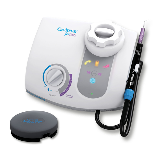
- Page 1 Cavitron JET Plus ® Ultrasonic Scaler & Air Polishing Prophylaxis System with Installation and Service Manual Please read carefully and completely before operating unit.
-
Page 5: Quick Reference Guide
Quick Reference Guide Power Control Diagnostic Display Power Level Control ON/OFF Turn knob to select ultrasonic power Illuminates when the Main Power level for operation. Turning the knob On/Off Power switch is in the “ON” clockwise increases the distance the (I) position. -
Page 6: Table Of Contents
TABLE OF CONTENTS 8 7 1 Accessories QuiCk START 8 7 2 User Replaceable Part iNSTALLATiON iNSTRuCTiONS Kits QuiCk START uSER GuiDE SySTEm SETuP, OPERATiON AND TEChNiQuES FOR uSE QuiCk REFERENCE GuiDE: 9 1 Handpiece Setup DiAGNOSTiC DiSPLAy 9 2 Turbo Mode iNTRODuCTiON 9 3 Boost Mode PRODuCT OvERviEw... -
Page 7: Introduction
DENTSPLY Professional is an ISO 13485 registered with the quality and reliability you’ve come to expect from company. All DENTSPLY Professional medical devices sold Cavitron brand ultrasonic systems. -
Page 8: Technical Support
A.M. to 5:00 P.M. (Eastern Time). For other areas, contact Although no instance of interference has ever been your local DENTSPLY Professional representative. reported to DENTSPLY, we recommend that the handpiece and cables be kept 6 to 9 inches (15 to 23 SuPPLiES &... -
Page 9: 1 System Precautions
In general it is recommended SECTiON 4: Precautions that ultrasonic inserts be discarded and replaced after one year of use to maintain optimal efficiency and avoid breakage. A DENTSPLY Professional Insert 4 1 System Precautions Efficiency Indicator is enclosed for your use. •... -
Page 10: Adverse Reactions
Cavitron Customer Service at 1-800-989-8826, Monday through system. Friday, 8:00 A.M. to 5:00 P.M. (Eastern Time). For areas outside the U.S., contact your local DENTSPLY • Incoming water temperature to the Cavitron System Professional representative. -
Page 11: 3 Electrical Requirements
7 3 Electrical Requirements has more than one Cavitron JET Plus system, it is ® recommended that you mark the Tap-On Foot Pedal • Incoming power to the system must be 100 volts AC to and base unit for easy reference as to which Tap-On 240 volts AC, single phase 50/60 Hz capable of Foot Pedal operates with which base unit. -
Page 12: 8 Air Supply Line Connection
7 9 Tap-On Foot Pedal Battery pressure by pressing the tip of the connector in an appropriate container and allow water to drain. To installation/Replacement remove the hose from the system, push on the outer ring of the system’s water inlet and gently pull out the water •... - Page 13 Install a new set of “AA” batteries into the Foot Pedal (see Section 7.9). Leave the battery cover of the Tap-On Foot Pedal open so the red push button is accessible. Maintain a distance of no more than 10 feet (3 meters) between the base unit and Tap-On Foot Pedal during the synchronization process.
-
Page 14: Jet Plus Combination
SECTiON 8: Cavitron JET Plus Combination System Description ® 8 1 System Controls Ultrasonic Power Level Control Turn knob to select the ultrasonic power level for operation. Turning the knob clockwise increases the distance the insert tip moves (stroke) without changing the frequency; turning the knob counterclockwise decreases the distance the insert tip moves (stroke) without changing the frequency. -
Page 15: 2 Diagnostic Display Indicators And Controls
8 2 Diagnostic Display indicators and Control Low Battery Indicator Illuminates when the Tap-On Foot Pedal battery power is approaching end of life. Replace batteries as instructed in Service Indicator Section 7.9. Illuminates when the system is not functioning properly. This display has three distinct modes. -
Page 16: 3 Handpiece/Cable
8 3 handpiece / Cable Lavage Control Turn the Lavage Control to select flow rate during system operation. Flow rate is based on a scale from 1 to 6. Turn clockwise toward 6 to increase flow at insert tip. Turn counter-clockwise toward 1 to decrease flow. -
Page 17: 5 Cavitron Jet Air Polishing Inserts
6. Lavage (Water) Filter, 10/Pack, Part Number 90158 period of approximately 5 seconds. The two buttons will blink approximately 6 times. When the buttons are released, For detailed information, contact your local DENTSPLY they will blink an additional 6 times to confirm Tap-On mode Professional Representative or authorized DENTSPLY has been disabled. -
Page 18: System Setup, Operation And Techniques For Use
(arrows will illuminate to show you are in “Turbo” mode). DENTSPLY recommends that the clinician familiarize themselves with the available power levels throughout the power knob rotation in both normal and turbo modes. To do this, simply hold your favorite insert over the sink and adjust •... -
Page 19: 6 Patient Comfort Considerations
in bottles. Keep stored in a location that does not insert tip is placed in the patient’s mouth, the lips, exceed 95 cheek and tongue should be retracted to prevent accidental (prolonged) contact with the activated tip. • A special container is provided with your System for use in emptying the powder bowl. -
Page 20: 9 Proper Angulation Of The Air Polishing Insert
• Flush the patient’s tongue with water to help reduce the Approximate Cycle Times saline taste. Prophy Mode Air Polish Rinse • The recommended normal procedure is to clean 1-3 teeth with the air polishing spray and then rinse the NONE* CONVENTIONAL area with water in order to inspect the work site before... -
Page 21: System Care
SECTiON 10: System Care Polishing Insert into the handpiece and adjust the Power Level Control to Prophy Mode, and the Powder Flow and Lavage Controls to your preferred operating It is recommended that you perform the following positions. maintenance procedures. BETWEEn PATIEnTS: 10 1 Daily maintenance Remove the used Cavitron... -
Page 22: Shut-Down Procedures At The End Of The Day
SHUT-DOWn PROCEDURES AT THE EnD by ordering Part Number 90158 from your local DENTSPLY Professional distributor. OF THE DAy: 1. Follow the “Between Patients“ maintenance procedures, 1. Verify that the system is turned OFF. steps 1 through 6. In addition, it is recommended to 2. -
Page 23: Troubleshooting
Although service and repair of the Cavitron JET Plus ® Mode. Combination System should be performed by DENTSPLY Check the insert for damage and that it is properly personnel, the following are some basic troubleshooting installed in the handpiece. procedures that will help avoid unnecessary service calls. -
Page 24: 11 2 Technical Support And Repairs
4. If service indicator still blinks, refer to Section 11.2 11 2 Technical Support and Repairs Technical Support and Repairs to have unit serviced as soon as possible. For technical support and repair assistance call DENTSPLY Symptom: Professional Cavitron Care Factory Certified Service at System operates: Service Indicator illuminated 1-800-989-8826 Monday through Friday, 8:00 A.M. -
Page 25: Classifications
SECTiON 13: Specifications, continued Dimensions Height: 6 in. (15,24 cm) Width: 9.5 in. (24,13 cm) Depth: 8 in. (20,32 cm) Handpiece Cable length: 6.5 ft. (2.0 M) Auxillary Footswitch Cable length: 8 ft. (2.4 M) Water Supply Line length: 8 ft. (2.4 M) Air Supply Line length: 10 ft. -
Page 26: Electromagnetic Compatibility Precautions
SECTiON 16: Electromagnetic Compatibility Precautions Guidance And Manufacturer’s Declaration - Electromagnetic Emissions The Ultrasonic Scaler model G137 is intended for use in the electromagnetic environment specified below. The customer or the user of the Ultrasonic Scaler should assure that it is used in such an environment. - Page 27 Guidance And Manufacturer’s Declaration - Electromagnetic Emissions The Model G137 is intended for use in the electromagnetic environment specified below. The customer or the user of the Model G137 should assure that it is used in such an environment. Compliance IEC 60601 Electromagnetic environment - guidance Immunity test...
- Page 28 Recommended separation distance between Portable and mobile RF communications equipment and the model @ 3Vrms The model G137 is intended for use in an electromagnetic environment in which radiated RF disturbances are controlled. The customer or the user of the Model G137 can help prevent electromagnetic interference by maintaining a minimum distance between portable and mobile RF communications equipment (transmitters) and the Model G137 as recommended below, according to the maximum output power of the communications equipment.
-
Page 29: Quick Reference Guide: Troubleshooting
SECTiON 17: QuiCk REFERENCE GuiDE: TROuBLEShOOTiNG ACTiON TAkEN SymPTOm Check that the Main Power Switch is in the ON (I) position, and that the detachable power cord is fully seated in the System will not receptacle on back of system. operate: No Power Check that the system’s power cord plug is fully seated in an appropriate AC wall outlet. -
Page 30: Analysis
3. Unit improperly calibrated. 3. a. Return the Cavitron JET Plus unit to ® DENTSPLY for factory certified service. b. Refer to DENTSPLY Professional Division- Product Service SOP PS-00176. - Page 31 SECTiON 18: G137 Cavitron JET Plus Troubleshooting and Analysis ® , cont This troubleshooting section is meant for use by qualified Cavitron Service Technicians. ® SymPTOmS CAuSES CORRECTivE mEASuRES Intermittent scaling power or no 1. Insert malfunction. 1. Test with another Cavitron insert.
- Page 32 SECTiON 18: G137 Cavitron JET Plus Troubleshooting and Analysis ® , cont This troubleshooting section is meant for use by qualified Cavitron Service Technicians. ® SymPTOmS CAuSES CORRECTivE mEASuRES Intermittent scaling power or no 9. Foot Pedal malfunction. 9. Connect the auxiliary Foot Pedal cable between scaling power.
- Page 33 SECTiON 18: G137 Cavitron JET Plus Troubleshooting and Analysis ® , cont This troubleshooting section is meant for use by qualified Cavitron Service Technicians. ® SymPTOmS CAuSES CORRECTivE mEASuRES No water flow from handpiece 1. High dental office water pressure. 1. Install a water pressure regulator on the main with no insert installed.
- Page 34 Press the Purge button. 4. Open connection on the 4. Replace the handpiece cable assembly. Press handpiece cable assembly. the Purge Button. 5. Problem on the PC board(s). 5. Return the Cavitron JET Plus unit to ® DENTSPLY for factory certified service.
- Page 35 4. Problem on the PC board(s). 4. Return the Cavitron JET Plus unit to ® DENTSPLY for factory certified service. Info Center Service light is 1. Insert is damaged or out of 1. Install a new 30K Cavitron insert in the blinking slowly (1 blink per specification.
- Page 36 2. Insufficient air pressure is being 2. Check the dental office air supply for 65 to 100 supplied to the unit. psi air pressure. 3. Use of non-DENTSPLY powder. 3. Replace the powder with fresh DENTSPLY ® ® Prophy-JET or JET-Fresh™ Powder. ®...
- Page 37 (Continued) elements. remove moisture and contaminants. c. Return the Cavitron JET Plus unit to ® DENTSPLY for factory certified service. 8. Duckbill filters were removed or Return the Cavitron JET Plus unit to ® installed in reverse. DENTSPLY for factory certified service.
- Page 38 CAuSES CORRECTivE mEASuRES Abnormally high bleed air with 1. The pinch valve assembly is 1. Return the Cavitron JET Plus unit to DENTSPLY ® powder leaking. leaking air and not fully sealing for factory certified service. the red pinch tube.
-
Page 39: Disassembly And Service Procedures
SECTiON 19: B Fuse Testing Procedure: Disassembly and Service Procedures CAUTION: THIS UNIT CONTAINS COMPONENTS White Wire Black Wire WHICH ARE SUBJECT TO ELECTROSTATIC DISCHARGE (ESD) DAMAGE. THE WORKSTATION SURFACE AND REPAIR TECHNICIAN MUST BE PROPERLY GROUNDED PRIOR TO REMOVAL OF THE COVER. 1. - Page 40 16. Calibrate and final test the Cavitron JET Plus unit ® using the DENTSPLY Professional - Product Service Standard Operating Procedure, PS-00176. 17. Align the Top Cover on the Bottom Housing and securely fasten the six #6 x 1/2” Hi-Lo screws using a screwdriver.
-
Page 41: Power Supply
20. Calibrate and final test the Cavitron JET Plus unit ® ground terminal and lockwasher under the left screw. using DENTSPLY Professional - Product Service 12. Connect the small clear Handpiece tube to the top port Standard Operating Procedure, PS-00176. of the Water Regulator/Solenoid tube. - Page 42 JET Plus unit ® with the two #8 x 1/2” Hi-Lo screws using a using DENTSPLY Professional - Product Service screwdriver. Install and tighten the two #6 x 1/2” Standard Operating Procedure, PS-00176. Hi-Lo screws in the Power Supply assembly.
- Page 43 Ribbon Cable 17. Calibrate and final test the Cavitron JET Plus unit ® using DENTSPLY Professional - Product Service Info Center PCB Standard Operating Procedure, PS-00176. 18. Align the Top Cover on the Bottom Housing and securely fasten the six #6 x 1/2” Hi-Lo screws using i main Controller a screwdriver.
- Page 44 13. Use a screwdriver and remove the two #6 x 1/2” Main Controller Board Hi-Lo screws at the front corners of the Air/Water chassis assembly. Carefully lift up the chassis. Powder Bowl 14. Lift up the bracket and use a screwdriver to remove Assembly the two #6-32 x 5/16 screws under the Air Manifold Assembly.
- Page 45 JET Plus unit 14. Insert the blue Water hose into the lower right-hand hose ® using DENTSPLY Professional - Product Service connector in the back panel. Be sure it is fully seated. Standard Operating Procedure, PS-00176. 15. Insert the black Air hose into the lower left-hand 28.
- Page 46 m Air manifold Connections: Use numbers to reference the components and tube routing on the drawings at right. 1. 2.0 ± .125” - 1/8” Clear Tube (P/N 61693) 2. 18.0 ± .125” - 1/8” Yellow Tube (P/N 625036012) 3. 17.75 ± .25” - 1/8” Red Tube (P/N 61631) 4.
-
Page 47: Air And Water Flow Diagram
SECTiON 20: Air and water Flow Diagram... -
Page 48: Service Parts
SECTiON 21: Service Parts G-137 Cavitron JET Plus - Generator Assembly ® ITEM QUANTITY PART NO. DESCRIPTION 81651 Power Drive PCB Bracket Assembly 81635 Protective Cover, Power Entry 81665 Baffle (Electrical Protection) 81661-1 24V Power Supply Assembly 81713 Air/Water Chassis Assembly 81843 Decorated Base 81878... - Page 49 Service Parts, continued G-137 Cavitron JET Plus - Air / Water Chassis Assembly ® ITEM QUANTITY PART NO. DESCRIPTION 629205003 Water Regulator/Solenoid (Burkert) 623072001 Straight Union Fitting (John Guest) 712-00004 Plastic Cable Tie 81647 Mounting Bracket 586174003 #6-19 x 3/8” HI-LO PPH Screws 61679 Straight Fitting, 1/16 Barb x 10-32 60386...
- Page 50 Service Parts, continued G-137 Cavitron JET Plus - Cover Assembly ® ITEM QUANTITY PART NO. DESCRIPTION 81891 Powder Bowl Assembly 80502-1 Knob, Molded 81638 Pot Switch Harness 60366 Cable Tie (For Pot-Switch Harness) 81879 Cover, Decorated 81881 Molded Overlay & Label, Info Center 586172002 #4-24 x 1/2”...
- Page 51 Service Parts, continued G-137 Cavitron JET Plus - Powder Bowl Assembly ® ITEM QUANTITY PART NO. DESCRIPTION 80677 Pointer 628052002 O-Ring 80676 Powder Chamber Deflector 80675-1 Powder Bowl Cap 81634-1 Bowl Mount Skirt 81710 L-Shape Brackets 60898 #6-32 x 3/8” Machine Screws 81712 Powder Bowl Housing 586172001...
- Page 52 Service Parts, continued G-137 Cavitron JET Plus - Power Supply ® ITEM QUANTITY PART NO. DESCRIPTION 81661-1 24 V Power Supply...
- Page 53 Service Parts, continued G-137 Cavitron JET Plus - Power Drive PCB Bracket Assembly ® ITEM QUANTITY PART NO. DESCRIPTION 81651 Power Drive PC Board Bracket Assembly...
- Page 54 Service Parts, continued G-137 Cavitron JET Plus - Info Center PC Board Assembly ® ITEM QUANTITY PART NO. DESCRIPTION 81852 Info Center PC Board Assembly 81720 Cover, Protective...
- Page 55 Service Parts, continued G-137 Cavitron JET Plus - Main Controller PC Board Assembly ® ITEM QUANTITY PART NO. DESCRIPTION 81848 Main Controller PC Board Assembly...
- Page 56 Service Parts, continued G-137 Cavitron JET Plus - Tap-On Foot Pedal ® ™ ITEM QUANTITY PART NO. DESCRIPTION 81872 Foot Pedal, Tap-On™ (Packed w/Synchronizing Instructions and 4 “AA” Batteries) 81680 Battery Door and Screw Kit 81681 Foot Pedal Pad (Bottom) 81663-2 Auxiliary Foot Pedal Cable with Ferrite...
- Page 57 Service Parts, continued G-137 Cavitron JET Plus - Miscellaneous Parts ® ITEM QUANTITY PART NO. DESCRIPTION 586172005 #6-19 x 1/2” HI-LO Torx, Pan (Base to Cover) 8170201 JET-Mate Handpiece (1-Pack) 8170203 JET-Mate Handpiece (3-Pack) 81717 Nozzle Grip, JET-Mate Handpiece 81884 G-132 Handpiece Cable, Black 603034001 Ferrite Block, Snap-On (For HP Cable)
- Page 60 U n i t e d K i n g d o m I t a l i a C a n a d a DEnTSPLy Ltd DEnTSPLy DeTrey Italia s r l DEnTSPLy Canada Building 1 Via A Cavaglieri, 26...
Need help?
Do you have a question about the Cavitron JET Plus and is the answer not in the manual?
Questions and answers