
Subscribe to Our Youtube Channel
Related Manuals for Kane KANE975


Summary of Contents for Kane KANE975
- Page 1 KANE975 Industrial Flue Gas Analyser May 2020 Stock No: MAN00002 Rev: 1.00520 © Kane International Ltd...
-
Page 2: Table Of Contents
CONTENTS Page No: KANE975 OVERVIEW INSTRUMENT FEATURES AND KEYPAD KEYPAD BUTTONS INSTRUMENT LAYOUT BATTERIES BATTERY TYPE REPLACING BATTIERES TIME AND DATE CHARGING NIMH BATTERIES BATTERY DISPOSAL GENERAL SAFETY FIRST TIME USE MENU LIST GENERAL OPERATING PRINCIPLE STATUS STATUS PAGE 1... -
Page 3: Status
KANE DASHBOARD 32-36 ONLINE BOOKING PROCEDURE 34-36 ANALYSER ANNUAL SERVICE AND RECIRTIFY SERVICE CALIBRATE RECIRTIFY 37-39 RETURNING YOUR ANALYSER TO KANE PACKING YOUR ANALYSER WHEN WE RECEIVE YOUR ANALYSER WHERE TO SEND YOUR ANALYSER COLD WEATHER PRECAUTIONS SPECIFICATIONS 41-42 EU DECLARATIONS OF CONFORMITY... -
Page 4: Kane975 Overview
NDIR CO2 sensor for true CO2 measurement, all aspects of the combustion process can be monitored. In addition to the gas sensors the KANE975 also includes dual type K thermocouple inputs and differential pressure measurement. It is fitted with KANE wireless as standard for operation with the KANE Live Android application, further enhancing the user experience. -
Page 5: Instrument Features And Keypad
INSTRUMENT FEATURES AND KEYPAD Page 5... -
Page 6: Keypad Buttons
KEYPAD BUTTONS Icon Description ON/OFF PLAY/PAUSE PRINT/F1 HOME STORE/F2 DOWN BACK/CANCEL OK/ENTER Page 6... -
Page 7: Instrument Layout
INSTRUMENT LAYOUT Page 7... - Page 8 Thermocouple __ __ 1 1 1 Stainless Steel Shaft _ Depth Stop Cone _____ Hanging Hook Page 8...
-
Page 9: Batteries
TIME AND DATE When changing batteries, the time and date will need setting. CHARGING NIMH BATTERIES The KANE975 employs an advanced power management system to ensure optimal performance. When a low battery event is detected the management software will warn the user until the battery reaches a critical level of discharge, at this point the unit will shut down. -
Page 10: Battery Disposal
If the user attempts to turn on the analyser while the batteries are discharged the power management system will prevent turn Under normal circumstances charging is simply a case of plugging in the supplied 12V charger (CU12VDC2A1), the analyser will automatically activate battery charging and indicate the progress on the display. -
Page 11: General Safety
GENERAL SAFETY SAFETY WARNING This analyser extracts combustion gases that may be toxic in relativity low concentrations. These gases are exhausted from the bottom of the analyser. This analyser must only be used in well-ventilated locations by trained and competent persons after due consideration of all the potential hazards. -
Page 12: First Time Use
FIRST TIME USE Charge the battery for 12 hours. Following this, an overnight charge should be sufficient for an average 8-hour day. Take time to read the manual fully, be aware that the analyser configuration that you have purchased may not support all the features detailed in this manual. -
Page 13: General Operating Principle
GENERAL OPERATING PRINCIPLE Use the UP/DOWN keys to move the cursor. Press OK to select a line. This is the way all the menus work. Press HOME at any time to get back. STATUS These pages list the current setup of the analyser PAGE 1 PAGE 2 PAGE 3... -
Page 14: Menu Setting And Setup
Select, OFF or user selectable max value (up to Over Range Protection the overload value of the CO fitted sensor) PRINTER Select, Wireless (Android app), KANE IRP, KANE IRP2 NOTE: Can only be changed if all logs in SET TIME memory have been cleared. HH:MM:SS format E.g. -
Page 15: Analyser Units
ANALYSER UNITS MENU ITEM OPTIONS/COMMENTS FUEL ORIGIN Select desired option via UP/DOWN and OK to confirm Select desired option via UP/DOWN and OK to confirm FUEL TYPE EFFICIENCY Select Gross, Net or Condensing GAS UNITS Select desired option via UP/DOWN and OK to confirm TEMPERATURE Select desired option via UP/DOWN and OK to confirm NOTE: Select m/s for PITOT. -
Page 16: Screen
SCREEN MENU ITEM OPTIONS/COMMENTS Choose font size MODE LINE 1-6 Choose displayed parameter LINE 7-12 Choose displayed parameter LINE 13-18 Choose displayed parameter Choose displayed parameter LINE 19-24 Changing the font size, changes the appearance of RESTORE USER LINES displayed pages. The larger the font size the more DEFAULTS pages are needed to display a particular function REPORTS... -
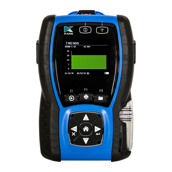
Page 17: Trends
TRENDS MENU ITEM OPTIONS/COMMENTS Set lower and upper LOG range REPORTS RANGE TRENDS SETUP See below Switch to display screen START TREND A START TREND B Switch to display screen START TREND C Switch to display screen Switch to display screen START TREND D START DUAL TREND AB Switch to display screen... -
Page 18: Service
SERVICE Restricted area. MANUAL AIR ZERO Use this function to reset toxic sensor to 0 ppm and the oxygen sensor to 20.95%. It is recommended that sensors are purged in fresh (outside) air for at least three minutes before zeroing. If the analyser is zeroed with its probe still in the flue, erroneous reading may result. -
Page 19: Using The Analyser
USING THE ANALYSER EVERY TIME YOU USE THE ANALYSER BEFORE SWITCH-ON CHECK THAT: • The particle filter is dry and clean • The water trap and probe line are empty of water • All hoses connections, etc, are properly made •... -
Page 20: Main Displays
MAIN DISPLAYS NOTE! Check for correct date and time before starting to take readings. Press the UP or DOWN key to get to the second display Page 20... -
Page 21: Logging Data
TIP: Make a note of the LOG NO. of particular tests for reference later PRINTING DATA Use the SETUP menu to configure the KANE975 for the correct printing configuration including Wireless. Press and hold the PRINT key until the display changes to show print progress. -
Page 22: Sampling The Flue Gas
SAMPLING THE FLUE GAS Once the automatic calibration procedure has been completed and the specific fuel has been selected (See SELECT menu) the probe can be inserted into the desired sampling point. It is recommended that the sampling point be located at least two flue diameters downstream of any bend and that the probe tip is in the centre of the flue. -
Page 23: Taking A Pressure Reading
To perform a combustion test and display draught at the same time a special probe is required, contact Kane International or an Authorised Distributor for details. TAKING A FLOW READING In the UNITS menu set the pressure units to metres/sec (m/sec), these are the only units available for the flow measurements. -
Page 24: Normal Shutdown Sequence
NORMAL SHUTDOWN SEQUENCE DO THIS EVERY TIME YOU USE THE ANALYSER Remove the probe from the flue - TAKE CARE! THE PROBE WILL BE HOT – and allow to cool naturally. Allow the analyser to purge in fresh air for at least three minutes or preferably until all toxic sensor readings are below 10 ppm. -
Page 25: Standard Printout
STANDARD PRINTOUT The Standard printout is: SOFTWARE COMPATIBILITY • ANDROID: KANE LIVE and Wireless Printer App • IOS: Wireless Printer App Page 25... -
Page 26: Storing And Retrieving Logs
STORING AND RETRIEVING LOGS STORING A LIVE TEST STEP OPTIONS/COMMENTS Press (To store live readings) The log number will (briefly) be displayed in the top left hand corner VIEW STORED LOG STEP OPTIONS/COMMENTS Press the Home Key Navigate to “REPORTS” using the Up/Down keys and select with the Enter Select “VIEW REPORTS”... -
Page 27: Printing A Stored Log
PRINTING A STORED LOG STEP OPTIONS/COMMENTS Select the desired log and press DELETING STORED LOGS STEP OPTIONS/COMMENTS Select “DELETE ALL REPORTS” from the Reports menu When prompted to “DELETE ALL” select “Yes” using the Up key and press the Enter key to confirm SETTING THE AUTO LOG TIME STEP... -
Page 28: Start Auto Log
START AUTO LOG STEP OPTIONS/COMMENTS Select “START AUTO LOG” from the Reports menu When prompted to start select “Yes” using the Ensure the desired interval has been set. Up key and press the Enter key to confirm START AUTO PRINTING STEP OPTIONS/COMMENTS Select “START AUTO... -
Page 29: Averaged Reports
AVERAGED REPORTS Average reports allow for a sample interval and a sample period to be selected. The average of each measured and calculated reading will then be stored. For example, a sample period of 2 minutes and a sample time of 6 minutes would provide the average measurement of the 3 samples. -
Page 30: Maintenance
MAINTENANCE EMPTYING AND CLEANING THE INTEGRAL WATER TRAP The integral water trap should be checked and emptied on a regular basis, water vapour will condense and gather in the probe line. This may move suddenly to the trap when the probe is moved, care should be taken at all times. -
Page 31: Nox Calculation
Nitrogen oxides are typically created in the combustion process when burning fuels at high temperatures. The KANE975 is able to calculate the values of NOx in the combustion process in a number of ways depending on your particular configuration of sensors fitted. -
Page 32: Kane Dashboard
KANE DASHBOARD We really want you to register your Kane analyser at www.kane.co.uk to create your dashboard - your personal online analyser portal. Benefits include: An automatic reminder when it's time to Service - Calibrate – Recertify Our new simple online booking in procedure ensures you receive the fastest turnaround times possible Easy access to your analyser's calibration certificates &... - Page 33 An out of calibration analyser may mean your combustion reports are invalid. Page 33...
-
Page 34: Online Booking Procedure
ONLINE BOOKING PROCEDURE @ www.kane.co.uk To organise your Kane analyser’s Service & Recertification online it must be registered. To register, click If you have already registered, click to sign in From your dashboard, click for the analyser you wish to organise Service &... - Page 35 Book your service/recertification & order any additional spare parts you need Once happy with your order just confirm & pay Page 35...
- Page 36 See your order & print out the return to Kane label Don’t forget to put the label on your package and send it to us Page 36...
-
Page 37: Analyser Annual Service And Recirtify
Please contact us on our Freephone number: 0800 059 0800 Outside UK call: +44 1707 375550 By sending your analyser back to Kane for an annual fixed price service (check www.kane.co.uk for details) you have the opportunity to extend the warranty on your analyser to 5 years. - Page 38 ✓ You can organise your Kane analyser’s Service & Recertification online via your Dashboard on www.kane.co.uk, send it or call us to arrange a pre-booked while-you-wait service, saving you time & potential lost revenue. We pride ourselves on our fast turnaround for a fixed price, which includes: - Inspecting your analyser &...
-
Page 39: Returning Your Analyser To Kane
Before sealing your package, please ensure you followed our procedure above & have clearly marked your box for the Kane Service Team. If you do not have an account with a courier company, take your package to your local Post Office –... -
Page 40: Where To Send Your Analyser
WHERE TO SEND YOUR ANALYSER Northern Customer Service Southern & International Customer Service Kane International Ltd Kane International Ltd Gibfield Park Avenue Kane House, 11 Bessemer Road Atherton, Welwyn Garden City Manchester Hertfordshire M46 0SY, UK AL7 1GF, UK e: nservice@kane.co.uk e: sservice@kane.co.uk... -
Page 41: Specifications
SPECIFICATIONS RESOLUTION ACCURACY RANGE PARAMETER Temperature Measurement & Pressure Measurement 0.1°C -50 – 1200°C with suitable Flue Temperature + _ 1°C + _ 0.3%reading probe Inlet Temperature 0.1°C + _ 1°C 0 – 50°C + _ 0.3%reading Pressure 0.1mbar +0.5% full scale 150 mbar Gas Measurement*1 Oxygen... - Page 42 Sulphur Dioxide 1ppm +5ppm<100ppm 0 – 5000ppm (optional) +5%>100ppm Carbon Dioxide 0.1% +0.3% reading 0 – 20% Infra-red Carbon Dioxide *2 0.1% +0.3% reading 0 – 99.9% Losses*2 0.1% +1.0% reading 0 – 99.9% Efficiency *2 0.1% +1.0% reading 0 –120% Excess Air*2 0.1% +0.2%...
-
Page 43: Eu Declarations Of Conformity
Restriction of the use of certain hazardous substances in electrical and electronic equipment (RoHS) The following harmonised standards and technical specifications have been applied: Certification The KANE975 is TUV-tested and certified to EN 50379, Parts 1-3 in accordance to 1st German Federal Emission Control Ordinance (BlmSchV) EN50270:2015 Safety... - Page 44 RoHS Distributor: sales@norrscope.com Page 44...
Need help?
Do you have a question about the KANE975 and is the answer not in the manual?
Questions and answers