Table of Contents
Advertisement
ISO 9001
C e r t i f i e d
Ascon Tecnologic srl
via Indipendenza 56,
27029 Vigevano (PV)
Tel.: +39-0381 69 871
Fax: +39-0381 69 8730
Internet site:
www.ascontecnologic.com
E-Mail address:
sales@ascontecnologic.com
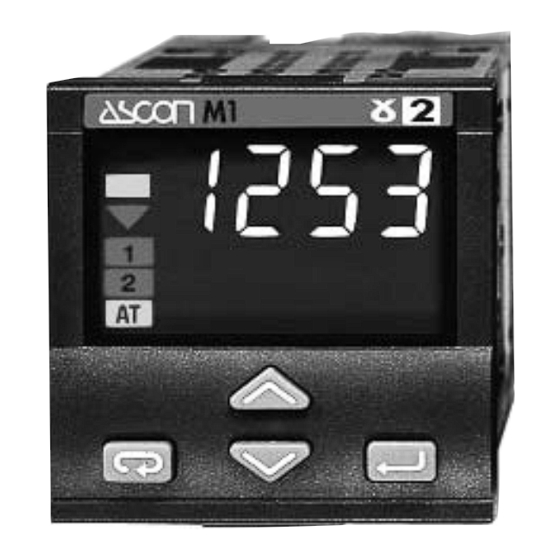
Temperature
Controller
1
/
DIN - 48 x 48
16
M1 line
U s e r m a n u a l • M . I . U . M 1 - 5 / 0 9 . 0 5 • C o d . J 3 0 - 4 7 8 - 1 A M 1 I E
c
c
Advertisement
Table of Contents

Subscribe to Our Youtube Channel
Related Manuals for ascon M1 line


Summary of Contents for ascon M1 line
- Page 1 Controller DIN - 48 x 48 M1 line ISO 9001 U s e r m a n u a l • M . I . U . M 1 - 5 / 0 9 . 0 5 • C o d . J 3 0 - 4 7 8 - 1 A M 1 I E...
- Page 2 Temperature Controller DIN - 48 x 48 M1 line...
- Page 3 information Please, read carefully these instructions before proceeding with the installation of the controller. Class II instrument, rear panel mounting. OTES ON ELECTRIC This controller has been designed with compliance to: Regulations on electrical apparatus (appliance, systems and installa- SAFETY AND tions) according to the European Community directive 73/23/EEC amend- ELECTROMAGNETIC ed by the European Comunity directive 93/68/EEC and the Regulations...
-
Page 4: Table Of Contents
Table of contents ABLE OF ONTENTS Page NSTALLATION ........................... Page LECTRICAL CONNECTIONS ..................Page RODUCT CODING ......................Page PERATIONS ..........................Page UTOMATIC ....................... Page ECHNICAL SPECIFICATIONS ................... Resources Operating mode Control Alarms Retransmission Main universal input Indication OP1 OP2 OP4 only Single OP2 OP4... - Page 5 1 - Installation INSTALLATION 1.1 GENERAL DESCRIPTION IP20 Terminal block Installation must only be carried EN61010 - 1 (IEC1010 - 1) out by qualified personnel. Before proceeding with the instal- lation of this controller, follow the instructions illustrated in this man- Panel surface ual and, particularly the installation precautions marked with the B...
- Page 6 1 - Installation 1.2 DIMENSIONAL DETAILS 1.3 PANEL CUT-OUT mm min. 1.89 2.56 in min. 1.89 mm max. 0.79 in max. +0.6 mm 1.78 +0.023 in 4.72...
- Page 7 1 - Installation 1.4 ENVIRONMENTAL RATINGS Operating conditions Altitude up to 2000 m Temperature 0…50°C [1] Relative humidity 5…95% non-condensing Special conditions Suggestions Altitude > 2000 m Use 24Vac supply version Temperature >50°C Use forced air ventilation Humidity > 95 % Warm up Conducting atmosphere Use filter...
- Page 8 1 - Installation 1.5 PANEL MOUNTING [1] 1.5.1 INSERT THE INSTRUMENT 1.5.2 INSTALLATION SECURING 1.5.3 CLAMPS REMOVING 1 Prepare panel cut-out 1 Position the mounting clamps 1 Insert the screwdriver in the clips 2 Check front panel gasket posi- 2 Push the mounting clamps of the clamps tion towards the panel surface to...
-
Page 9: E Lectrical Connections
2 - Electrical connections ELECTRICAL CONNECTIONS 2.1 TERMINAL BLOCK [1] Rear terminal cover 5.7 mm F50- 0.22 in 474 1A1M1 Wire size 1 mm (18 AWG Solid/ Stranded) [2] Terminals Pin connector 14 screw terminals q 1.4 mm 0.055 in max. Option terminals Fork-shape Tightening torque... - Page 10 2 - Electrical wirings PRECAUTIONS 2.2 PRECAUTIONS AND ADVISED CONDUCTOR COURSE Despite the fact that the instrument Conduit for supply and output cables has been designed to work in an harsh and noisy environmental (level IV of the industrial standard IEC 801-4), it is strongly recom- mended to follow the following suggestions.
- Page 11 2 - Electrical connections 2.3 EXAMPLE OF WIRING DIAGRAM Supervision Supply Retransmission Notes: 1] Make sure that the power supply voltage is the same indicated on Power supply the instrument. switch RS485 2] Switch on the power supply only after that all the electrical con- RX/TX 4…20mA nections have been completed.
- Page 12 2 - Electrical connections 2.3.1 POWER SUPPLY 2.3.2 OP1 OUTPUT Switching power supply with mul- A] Single relay output Fuse tiple isolation and internal PTC • NO contact for resistive load of • Standard version: up to 2A/250Vac (4A/120Vac) Nominal voltage: max.
- Page 13 2 - Electrical connections OP2 OUTPUT 2.3.4 OP4 OUTPUT (option) OP2 output can be relay (Std) or PV retransmission SSR drive. • Galvanic isolation Load The “jumper” on the auxiliary 500Vac/1 min board selects the output type: • 0/4...20mA (750Ω or 15Vdc max.) Link Pins 1-2 for OP2-Relay Link Pins 2-3 for OP2-SSR drive...
- Page 14 2 - Electrical connections 2.3.6 PV CONTROL INPUT • Connect the wires with the For L J K S T thermocouple type For mA, mV and V polarity as shown mV mA • Use always compensation cable of the correct type for the ther- mocouple used •...
-
Page 15: P Roduct Coding
3 - Product coding PRODUCT CODING The complete code is shown on the instrument label. The informa- Instrument label 3000 tions about product coding are accessible from the front panel by mean of a particular procedure described at section 4.2.2 page 19 : M1-3000-0000 CONF : 2002... - Page 16 3 - Product coding Line Basic Accessories Configur. 3.1 MODEL CODE Model: A B C D 0 F G 0 / I L M N The product code indicate the spe- Line cific hardware configuration of the instrument, that can be modified Power supply by specialized engineers only.
- Page 17 3 - Product coding Input type and range CONFIGURATION CODING TR Pt100 IEC751 -99.9…300.0 °C -99.9…572.9 °F TR Pt100 IEC751 -200…600 °C -328…1112 °F The configuration code consists of 4 digits that identify the operat- TC L Fe-Const DIN43710 0…600 °C 32…1112 °F ing characteristic of the controller, TC J Fe-Cu45% Ni IEC584...
- Page 18 3 - Product coding Alarm 2 type and function Not active If, when the controller is powered Sensor break alarm up for the first time, the display shows the following message active high Absolute active low active high Conf Deviation [1] active low active out (of the band) Deviation...
-
Page 19: O Perations
4 - Operations OPERATIONS 4.1 KEYPAD COMMANDS AND DISPLAY • PV control input (operator mode) (in engineering units) when the measured value is greater than sensor high range when the measured value is less than • Deviation indicator (SP-PV) the sensor low range Green led ON ±1% •... - Page 20 4 - Operations 4.2 DISPLAY 4.2.1 OF THE PROCESS 4.2.2 OF THE CONFIGURATION VARIABLES CODES When the display operation is 274. 8 274. 8 selected, the controller presents Operator Operator mode mode automatically all the most impor- tant parameters and configuration after information.
- Page 21 4 - Operations 4.3 PARAMETER SETTING 4.3.1 NUMERIC ENTRY 4.3.2 MNEMONIC CODES SETTING (i.e. the modification of the value of a stored Setpoint from 275.0 to 240.0) (e.g. configuration see pages 26, 27) Press S or G momentarily to Press the S or G to display the Operator mode 274.
- Page 22 4 - Operations 4.4 SPECIAL FUNCTIONS 4.4.1 KEYPAD LOCK 4.4.2 OUTPUTS LOCK Unit Engineering Units To lock/unlock the keypad press The outputs are switched to the í è the keys simulta- OFF status by pressing the keys í neously for 2 seconds. together.
- Page 23 4 - Operations 4.4 PARAMETERIZATION 1st GROUP 274. 8 A1s. p AL1 alarm threshold [1] (see pag. 24) Password entry PASS Code only if value A2s. p AL2 alarm threshold [2] ≥5000 (see pag. 24) (see pages 26…27) Values modification Parameter Modification/ menu...
- Page 24 4 - Operations PARAMETER MENU 2nd GROUP Password entry tune pass Code only if Tune run/stop value <5000 (PID algorithm only) (see pages 26…27) Direct access to the configuration (pages 26 … 27) Setpoint ramp up sl. u (not available with 2 alarms) Filter time constant t.
- Page 25 4 - Operations Sensor break or input disconnection PARAMETER specifies the time required by the Sensor Visualisation integral term to generate an output 1st GROUP over-range equivalent to the proportional term. When Off the integral term is not The controller parameters have been organized in group, accord- included in the control algorithm.
- Page 26 4 - Operations # s . p . l Filter response effectiveness of the PID algorithm. Setpoint Setting 1, the overshoot control is low limit 100% disabled. Low limit of the setpoint value. 63,2% When the parameter is Off, this # O p.
- Page 27 4 - Operations 4.6 CONFIGURATION ONFIGURATION MENU Operator mode 1st GROUP The configuration of the controller 274. 8 PASS AIs. p Password entry is specified through a 4 digit code Code only if value ≥5000 that defines the type of input, of control output and of the alarms.
- Page 28 4 - Operations Note: Pressing the Q the next group of 2nd GROUP parameters is displayed. tune pAss Password entry Code only if value <5000 [1] Table of the supported Engineering Units. °C Centigrade degrees * Code entry 0... 4999 (33 default from °f Fahrenheit degrees * factory) the entered pass-...
-
Page 29: Automatic Tune
5 - Automatic tune AUTOMATIC The green led 3 goes on when the This method has the advantage of Fuzzy Tuning is in progress. At the a better accuracy in the term cal- TUNE end of this operation, the calculat- culation with a reasonable speed ed PID terms parameter are stored calculation. -
Page 30: T Echnical Specifications
6 - Technical specification TECHNICAL SPECIFICATIONS Features Description (at 25°C enviromental temp.) Total configurability From keypad or serial communication the user selects: the type of input - the associated functions par. 3.2 pag. 16 and the corresponding outputs - the type of control algorithm - the type of output and the safe condi- par. - Page 31 6 - Technical specification Features Description (at 25°C enviromental temp.) AL1 alarm AL2 alarm Indicator with 2 alarms OP1 - relay or Triac OP2 - SSR drive or relay Operating mode OP2 - SSR drive or relay OP1 - relay or Triac and Outputs Control output AL2 alarm...
- Page 32 6 - Technical specification Features Description (at 25°C enviromental temp.) Ramp up and down. User inhibited 0.1…999.9 digit/min (OFF = 0) Setpoint Low limit From low range to the high limit High limit From low limit to the high range Galvanic isolation: 500 Vac/1 min OP4 PV retransmission Current output: 0/4…20mA 750Ω/15V max.
- Page 33 Guarantee WARRANTY We warrant that the products will be free from defects in material and workmanship for 18 months from the date of delivery. The warranty above shall not apply for any failure caused by the use of the product not in accordance with the instructions contained in this manual.
- Page 35 Icons table ICONS TABLE Digital input connected functions Main universal input Digital input Thermocouple Isolated contact Auto/Manual Run, Hold, Reset and RTD (Pt100) NPN open collector program selection Delta Temp (2x RTD) TTL open collector PV hold Setpoint slopes mA and mV inhibition Setpoint Custom...
Need help?
Do you have a question about the M1 line and is the answer not in the manual?
Questions and answers