Table of Contents
Advertisement
Quick Links
INSTRUCTION MANUAL AND PARTS LIST
DESCRIPTION
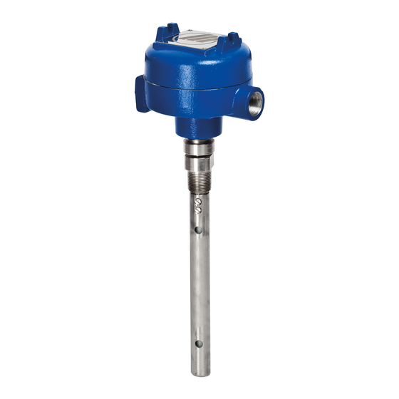
Kotron two-wire level transmitters are designed to measure
either liquid or certain dry bulk media. The transmitter is usu-
ally mounted integrally with the probe.
The 24 V DC 4 mA base current is the supply to the unit.
Changes in the level of the medium change this current
between 4 and 20 mA in the two-wire loop.
This transmitter is available with a variety of options includ-
ing an analog meter and rigid or flexible probes. This
instruction manual applies to 24 V DC models only.
OPERATING PRINCIPLE
The amount of capacitance developed in any vessel, is
determined by the size (surface area) of the probe, the
distance from the probe to its ground reference (e.g. tank
wall), and the dielectric of the medium it is measuring.
If the probe's mounting position is fixed, and the dielectric
value of the medium is constant, then the amount of
capacitance developed in any vessel becomes dependent
upon the probe's total surface area.
Adjusting the combination of the probe's diameter and
length (and of course its proximity to ground) in any given
application can generate the necessary capacitance
required by the electronic circuitry.
As media rises and falls in the tank, the amount of
capacitance developed between the sensing probe and the
ground also rises and falls. This change in capacitance is
converted into a pulse wave form, proportional to the
change in level. The amplifier then converts the proportion-
al pulse signal into a 4-20 mA output signal.
UNPACKING
Unpack the instrument
carefully. Inspect all units for dam-
age. Report any concealed damage to carrier within 24
hours. Check the contents of the packing slip and purchase
order. Check and record the serial number for future refer-
ence when ordering parts.
®
KOTRON
R.F. 2-WIRE
Level Transmitter
AGENCY
APPROVALS
Agency
Approval
ATEX
II 1G EEx ia II C T6, Intrinsically safe
Intrinsically safe:
Class
I,
Div. 1, Groups A, B, C & D;
Class
II,
Div. 1, Groups E, F & G;
FM/CSA
Class
III
CSA approval only valid with insulated probes.
Explosion proof:
➀
CSA
Class I,
Div. 1, Groups C & D;
Class
Div. 1, Groups E,F & G;
II,
➀
Consult factory for proper selection data.
®
Advertisement
Table of Contents

Subscribe to Our Youtube Channel
Related Manuals for Magnetrol Kotron RF 2-Wire Series


Summary of Contents for Magnetrol Kotron RF 2-Wire Series
- Page 1 KOTRON ® R.F. 2-WIRE ® Level Transmitter INSTRUCTION MANUAL AND PARTS LIST DESCRIPTION Kotron two-wire level transmitters are designed to measure either liquid or certain dry bulk media. The transmitter is usu- ally mounted integrally with the probe. The 24 V DC 4 mA base current is the supply to the unit. Changes in the level of the medium change this current between 4 and 20 mA in the two-wire loop.
- Page 2 MODEL IDENTIFICATION A complete measuring system consists of: Code for KOTRON ® electronics 2. Probe selection; a full range of rigid and flexible probes for conductive and non-conductive media is available (see bulletin BE 50-125) Code for KOTRON ® electronics 2 - 8 4 24 V DC, 2-wire KOTRON ®...
-
Page 3: Installation
Figure 1 Figure 3 – Threaded probe MOUNTING CAUTION: Packing glands used on all Magnetrol Two-wire transmitters with probes up to and including rigid probe assemblies have been sealed at the 305 mm (12") in length are shipped pre-assembled. Two- factory under controlled conditions. - Page 4 INSTALLATION (cont.) MOUNTING PROCEDURE C CAUTION: Unassembled transmitters, Apply wrench to lower packing gland nut only. integral mount with flexible probe NOTE: Do not allow the probe to fall in the tank while fol- CAUTION: Flexible probes are shipped with the lowing steps 7 through 11.
- Page 5 WIRING TRANSMITTERS WITHOUT METERS INTEGRAL MOUNT TRANSMITTERS W/METERS All wiring between the power supply and the transmitter All wiring between the power supply and the transmitter should be done with 18 AWG to 22 AWG shielded twisted should be done with 18 AWG to 22 AWG shielded twisted pair.
- Page 6 CALIBRATION AUXILIARY CURRENT METER TWO POINT CALIBRATION - LEVEL INCREASE In order to calibrate the transmitter, you may use either the Two calibration procedures are described on page 7. Follow loop current meter, or a second current meter which has an the one which fits your application.
-
Page 7: Calibration Procedure A
CALIBRATION (cont.) CALIBRATION PROCEDURE A CALIBRATION PROCEDURE B Move the material in the vessel to its L0 (0%) level. Set the material level in the vessel to L1, some point above 0%. Record the L1 level in mm, cm, inches, feet ➀, zero ➁... -
Page 8: Troubleshooting
TROUBLESHOOTING Problems which might be encountered during installation, c. Excessive probe capacitance calibration and operation of the Two-Wire Transmitter are - Maximum zeroing range is: listed below with their solutions. 450 pf-zero dip switch 1 in closed position 650 pf-zero dip switch 2 in closed position INSTALLATION 1000 pf-zero dip switch 3 in closed position - Decrease length of probe covered at zero level;... -
Page 9: Operation
TROUBLESHOOTING (cont.) OPERATION Loop current oscillates or hunts. 4. Loop current less than 4 mA. a. Waves or disturbances in medium a. Incorrect calibration - Use stilling well; or - Recalibrate unit. - Use external cage or standpipe for transmitter b. -
Page 10: Replacement Parts
REPLACEMENT PARTS METER TRANSMITTER Description Part Number Description Part Number 4-20 mA 30-9012-001 Meter Assembly 37-3145-001 P.C. Board 20-4 mA 30-9012-002 Base 04-9112-001 Base consult factory Cover Assembly 36-3908-001 Cover consult factory O-Ring 12-2501-246 1” x 3/4” Bushing 04-1739-001 O-Ring 12-2101-345 1.5"... -
Page 11: Integral Mount
DIMENSIONS in mm INTEGRAL MOUNT NOTES: Allow 102 (4.00) overhead clearance for cover removal. ø 118 ø 321 Blind transmitter Transmitter with (4.63) (12.65) with rigid probe analog meter ø 118 with rigid probe (4.63) (3.00) (3.00) 70 (2.75) Optional Mounting Optional 3/4"... - Page 12 Owners of Magnetrol products may request the return of a control; or, any part of a control for complete rebuilding or replacement. They will be rebuilt or replaced promptly. Magnetrol International will repair or replace the control, at no cost to the purchaser, (or owner) other than transportation cost if: a.
Need help?
Do you have a question about the Kotron RF 2-Wire Series and is the answer not in the manual?
Questions and answers