
Related Manuals for Magnetrol Kotron 805


Summary of Contents for Magnetrol Kotron 805
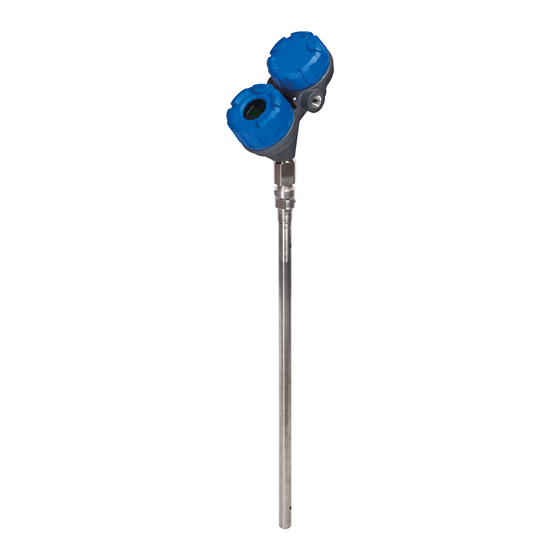
- Page 1 Kotron ® nstallation and Operating Manual R.F. Capacitance Level Transmitter ®...
- Page 2 24 hours. Check the contents of the car- Nameplate: ton/crates against the packing slip and report any discrep- - partnumber ancies to Magnetrol. Check the nameplate model number - amplifier - serial n° to be sure it agrees with the packing slip and purchase - tag n°...
- Page 3 CAUTION: ALWAYS check for proper grounding, Improper grounding will cause malfunction of the unit. CALIBRATION NOTE: When connected to an approved barrier, the intrinsically safe electronics of the Kotron 805 allow to remove both covers with power switched on – even if the area is known to be hazardous 2 line –...
- Page 4 New Pass Display shows an encrypted value, enter your password Data is protected by a valid 4096 or call Magnetrol for assistance to recoop your password Password if necessary New Pass Protect data by new password...
- Page 5 CALIBRATION - TRANSMITTER WITH LCD SCREENMENU: STEP BY STEP PROCEDURE Screen Action Comment Transmitter Display Transmitter default display. Level, % Output, and Loop *Level* *%Output* values cycle every 5 seconds. *Loop* Transmitter Display Transmitter displays Level measurement in cm or in. Level xx.x cm Transmitter Display...
- Page 6 IMPORTANT: Check whether your HART communicator is equiped with the 805 Device Descriptors (DD’s). Older pur- ® chased devices may require an update – consult your local HART Service Centre or Magnetrol for further assistance. CONNECTIONS Connection of your Hart communicator: •...
-
Page 7: Maintenance
(e.g., Mfgs. ID, Device #, account for Mfgs. ID #’s greater master software for upgrade. This is a Serial #, etc.) but will not read any than 63. Magnetrol’s ID is 86. shortcoming of early HART master process variables. software. -
Page 8: Replacement Parts
REPLACEMENT PARTS Partn°: Serial n°: See nameplate, always provide complete partn° and Digit in partn°: 8 9 10 serial n° when ordering spares. X = product with a specific customer requirement E X P E D I T E S H I P P L N ( E S P ) Several parts are available for quick shipment, within max. - Page 9 MAINTENANCE TROUBLESHOOTING FLOWCHART (LCD version) Start HART Unit Equipped Communications with Display? Active HART Display has Check Voltage at Text? Terminal Board See page 12 Some problems could be temporarily solved by power Check Power cycling the unit. Please call No Voltage? Supply and Wiring factory if this problem persists.
- Page 10 MAINTENANCE TROUBLESHOOTING FLOWCHART (LCD version) Failure to Operate Display with Correct Loop Reseat Boards Retest Working? Inputs Check Loop Loop Current Remove Electronic Loop Current Current at Terminal Above 23 mA? Module Above 1 mA? Board Replace Electronic Replace Terminal Module Board Good...
- Page 11 MAINTENANCE TROUBLESHOOTING FLOWCHART (LCD version) Unit with Display Communicates Call Factory "Software Error?" Corrupt Display Replace Electronic Text? Module "Uncal?" "Above Range?" "Corrupt "Shorted Probe?" Parameters?" Error "Open Probe?" "OSC Fail?" Displayed? Check Analog Check Calibration Parameters Parameters Check Probe and Connectors Same Error Analog Loop...
-
Page 12: Transmitter Specifications
TRANSMITTER SPECIFICATIONS FUNCTIONAL/PHYSICAL Description Specification Power (at terminals) General Purpose: 11 to 36 V DC ATEX Intrinsically Safe: 11 to 28.6 V DC Output 4-20 mA or 4-20 mA with HART ® 3.8 to 20.5 mA useable (meets NAMUR NE 43) Span minimum 5 pF - maximum 10.000 pF Zero and Range... -
Page 13: Dimensions In Mm (Inches)
DIMENSIONS in mm (inches) (4.12) (3.28) 45° View (8.43) (7.88) (4.94) (3.85) (4.38) Kotron 805 Housing front View 45° 2 cable entries Mounting Flange 220 (8.66) 220 (8.66) Optional Optional Mounting Mounting Flange Flange Probe Insertion 3/4" NPT 3/4" NPT Length 1"... - Page 14 IDENTIFICATION A complete measuring system consists of: 1. Kotron 805 transmitter head/electronics. 2. KOTRON Probe; a full range of rigid and flexible probes for conductive and non-conductive media is available ® (see bulletin BE 50-125). Rigid probes: from 150 mm (6") to 6000 mm (20') insertion length.
- Page 15 Notes...
-
Page 16: Service Policy
SERVICE POLICY Owners of Magnetrol products may request the return of a control; or, any part of a control for complete rebuilding or replacement. They will be rebuilt or replaced promptly. Magnetrol International will repair or replace the control, at no cost to the purchaser, (or owner) other than transportation cost if: a.
Need help?
Do you have a question about the Kotron 805 and is the answer not in the manual?
Questions and answers