
Related Manuals for DSE 8610 MKII


Summary of Contents for DSE 8610 MKII
- Page 1 DEEP SEA ELECTRONICS PLC DSE8610 MKII Operator Manual Document Number: 057-254 Author: Mark Graham 057-254 ISSUE: 2...
- Page 2 Applications for the copyright holder’s written permission to reproduce any part of this publication must be addressed to Deep Sea Electronics Plc at the address above. ® ® ® The DSE logo and the names DSEGenset , DSEAts and DSEPower are UK registered trademarks of Deep Sea Electronics PLC.
-
Page 3: Table Of Contents
DSE8610 MKII Operator Manual TABLE OF CONTENTS Section Page INTRODUCTION ....................8 CLARIFICATION OF NOTATION .................... 9 GLOSSARY OF TERMS ......................9 BIBLIOGRAPHY ........................11 1.3.1 INSTALLATION INSTRUCTIONS ................... 11 1.3.2 MANUALS ........................11 1.3.3 TRAINING GUIDES ......................12 1.3.4 THIRD PARTY DOCUMENTS .................. - Page 4 DSE8610 MKII Operator Manual ® 2.10.9 DSENET (EXPANSION MODULES) ................38 ® 2.10.9.1 DSENET USED FOR MODBUS ENGINE CONNECTION ........39 2.11 SOUNDER .......................... 40 2.11.1 ADDING AN EXTERNAL SOUNDER ................40 2.12 ACCUMULATED INSTRUMENTATION ................40 2.13 DIMENSIONS AND MOUNTING ..................41 2.13.1 DIMENSIONS ........................
- Page 5 DSE8610 MKII Operator Manual 3.5.5 MULTI GENERATORS & SYNCHRONISING TRANSFER SWITCHES ......80 3.5.6 MULTI GENERATORS & TRANSFER SWITCHES WITH BUS COUPLER ....81 3.5.7 SINGLE GENERATOR EXPORTING (BASE LOADING) POWER ........ 82 3.5.8 MULTI GENERATORS EXPORTING (BASE LOADING) POWER ........ 83 DESCRIPTION OF CONTROLS ................
- Page 6 EXITING THE ‘RUNNING’ CONFIGURATION EDITOR ..........169 7.2.5 RUNNING EDITOR PARAMETERS ................169 COMMISIONING ....................170 BASIC CHECKS ........................170 DSE 4 STEPS TO SUCCESSFUL SYNCHRONISING ............171 8.2.1 CONTROL ........................172 8.2.1.1 DETERMINING CONNECTIONS AND SETTINGS FOR GOVERNORS ..... 172 8.2.1.2...
- Page 7 DSE8610 MKII Operator Manual 10.1.2 INDIVIDUAL PLUGS ..................... 184 10.2 PURCHASING ADDITIONAL FIXING CLIPS FROM DSE ..........184 10.3 PURCHASING ADDITIONAL SEALING GASKET FROM DSE ........185 ® 10.4 DSENET EXPANSION MODULES ................185 WARRANTY ....................186 DISPOSAL ....................186 12.1...
-
Page 8: Introduction
This is not a controlled document. DSE do not automatically inform on updates. Any future updates of this document are included on the DSE website at www.deepseaplc.com The DSE86xx MKII series is designed to provide differing levels of functionality across a common platform. -
Page 9: Clarification Of Notation
Introduction 1.1 CLARIFICATION OF NOTATION Clarification of notation used within this publication. Highlights an essential element of a procedure to ensure correctness. NOTE: Indicates a procedure or practice, which, if not strictly observed, could CAUTION! result in damage or destruction of equipment. Indicates a procedure or practice, which could result in injury to personnel WARNING! or loss of life if not followed correctly. - Page 10 Introduction Term Description Global System for Mobile communications. Cell phone technology used in most of the World. HEST High Exhaust System Temperature Initiates when DPF filter is full in conjunction with an extra fuel injector in the exhaust system to burn off accumulated diesel particulate matter or soot. Human Machine Interface A device that provides a control and visualisation interface between a human and a process or machine.
-
Page 11: Bibliography
Introduction 1.3 BIBLIOGRAPHY This document refers to, and is referred by the following DSE publications which are obtained from the DSE website: www.deepseaplc.com or by contacting DSE technical support: support@deepseaplc.com. 1.3.1 INSTALLATION INSTRUCTIONS Installation instructions are supplied with the product in the box and are intended as a ‘quick start’... -
Page 12: Training Guides
Training guides are provided as ‘hand-out’ sheets on specific subjects during training sessions and contain specific information regarding to that subject. DSE Part Description 056-001 Four Steps To Synchronising 056-005 Using CTs With DSE Products 056-006 Introduction to Comms 056-010 Over Current Protection 056-011 MSC Link... -
Page 13: Specification
Specification 2 SPECIFICATION 2.1 OPERATING TEMPERATURE Module Specification DSE86xx MKII -30 ºC +70 ºC (-22 ºF +158 ºF ) Display Heater Variants -40 ºC +70 ºC (-40 ºF +158 ºF ) 2.1.1 SCREEN HEATER OPERATION Screen Heater Function Specification Turn On When Temperature Falls Below -10 ºC (+14 ºF) Turn Off When Temperature Rises Above -5 ºC (+23 ºF) -
Page 14: Terminal Specification
Specification 2.3 TERMINAL SPECIFICATION Description Specification Two part connector. Male part fitted to module Connection Type Female part supplied in module packing case - Screw terminal, rising clamp, no internal spring. Minimum Cable Size 0.5 mm² (AWG 24) Example showing cable entry and screw Maximum Cable Size 2.5 mm²... -
Page 15: Voltage & Frequency Sensing
Specification 2.5 VOLTAGE & FREQUENCY SENSING Description Specification Measurement Type True RMS conversion Sample Rate 40 kHz Harmonics Up to 21 or better Input Impedance 300 kΩ phase to neutral 15 V (minimum required for sensing frequency) to 415 V AC (absolute maximum) Phase To Neutral Suitable for 345 V AC nominal... -
Page 16: Va Rating Of The Cts
Specification 2.6.1 VA RATING OF THE CTS NOTE: Details for 4 mm² cables are shown for reference only. The connectors on the DSE modules are only suitable for cables up to 2.5 mm². The VA burden of the module on the CTs is 0.5 VA. However depending upon the type and length of cabling between the CTs and the module, CTs with a greater VA rating than the module are required. -
Page 17: Ct Polarity
2.6.3 CT PHASING Take particular care that the CTs are connected to the correct phases. For instance, ensure that the CT on phase 1 is connected to the terminal on the DSE module intended for connection to the CT for phase 1. -
Page 18: Inputs
Specification 2.7 INPUTS 2.7.1 DIGITAL INPUTS Description Specification 12 configurable digital inputs Number (16 when Analogue Inputs are configured as digital inputs) Arrangement Contact between terminal and ground Low Level Threshold 2.1 V minimum High Level Threshold 6.6 V maximum Maximum Input Voltage +50 V DC with respect to plant supply negative Minimum Input Voltage... -
Page 19: Analogue Inputs
All of the analogue inputs are flexible within the DSE8610 MKII module 2.7.3.1 ANALOGUE INPUT A Description Specification Flexible: Configured for Oil Sensor in the DSE default configuration. Input Type Flexible Options: Not used, Digital Input, Flexible Analogue Oil Sensor Flexible Input Selection... -
Page 20: Analogue Input B, C & D
2.7.3.2 ANALOGUE INPUT B, C & D Description Specification Flexible: Configured for Temperature Sensor in the DSE default Analogue Input B Type configuration. Flexible Options: Not used, Digital Input and Flexible Analogue Flexible: Configured for Fuel Sensor in the DSE default Analogue Input C Type configuration. -
Page 21: Charge Fail Input
Magnetic Pickup devices can often be ‘shared’ between two or more devices. For example, one device can often supply the signal to both the DSE module and the engine governor. The possibility of this depends upon the amount of current that the magnetic pickup can supply. -
Page 22: Outputs
Specification 2.8 OUTPUTS 2.8.1 DC OUTPUTS A & B (FUEL & START) Description Specification Normally used as Fuel & Start outputs. Type Fully configurable for other purposes if the module is configured to control an electronic engine. Rating 15 A resistive at Emergency Stop supply. 2.8.2 CONFIGURABLE VOLT-FREE RELAY OUTPUTS C &... -
Page 23: Communication Ports
Ethernet Auto detecting 10/100 Mbit Ethernet port. NOTE: For additional length, the DSE124 CAN & MSC Extender is available. For more information, refer to DSE Publication: 057-116 DSE124 Operator Manual MSC (Multi Set Standard implementation of ‘Slow mode’, up to 250K bits/s... -
Page 24: Communication Port Usage
2.10 COMMUNICATION PORT USAGE 2.10.1 USB SLAVE PORT (PC CONFIGURATION) NOTE: DSE stock 2 m (6.5 feet) USB type A to type B cable, DSE Part Number: 016-125. Alternatively they are purchased from any PC or IT store. NOTE: The DC supply must be connected to the module for configuration by PC. -
Page 25: Rs232 Port
The various operating parameters (such as coolant temperature, oil pressure, etc.) of the remote engine are viewed or changed. Many PCs are not fitted with an internal RS232 serial port. DSE DOES NOT recommend the use of USB to RS232 convertors but can recommend PC add-ons to provide the computer with an RS232 port. -
Page 26: Recommended Pc Rs232 Serial Port Add-Ons
Specification 2.10.2.2 RECOMMENDED PC RS232 SERIAL PORT ADD-ONS NOTE: DSE have no business tie to Brainboxes. Over many years, our own engineers have used these products and are happy to recommend them. NOTE: For further details of setting up the devices below, refer to the manufacture whose details are below. -
Page 27: Rs485 Port
The various operating parameters (such as coolant temperature, oil pressure, etc.) of the remote engine are viewed or changed. Many PCs are not fitted with an internal RS485 serial port. DSE DOES NOT recommend the use of USB to RS485 convertors but can recommend PC add-ons to provide the computer with an RS485port. -
Page 28: Recommended Pc Rs485 Serial Port Add-Ons
Specification 2.10.3.2 RECOMMENDED PC RS485 SERIAL PORT ADD-ONS NOTE: DSE have no business tie to Brainboxes. Over many years, our own engineers have used these products and are happy to recommend them. NOTE: For further details of setting up the devices below, refer to the manufacture whose details are below. -
Page 29: Rs485 Used For Modbus Engine Connection
Specification 2.10.3.3 RS485 USED FOR MODBUS ENGINE CONNECTION NOTE: For further details of module configuration, refer to DSE Publication: 057-238 DSE8610 MKII Configuration Suite PC Software Manual. The RS485 port can be configured for connection to Cummins MODBUS engines (Engines fitted with Cummins GCS (G-Drive Control System)). -
Page 30: Ethernet Port
NOTE: For further details of module configuration, refer to DSE Publication: 057-238 DSE8610 MKII Configuration Suite PC Software Manual. The DSE MODBUS register table for the controller is available upon request from the DSE Technical Support Department. Ethernet is used for point-to-point cable connection of more than one device and allows for connection to PCs, PLCs and Building Management Systems (to name just a few devices). -
Page 31: Direct Pc Connection
PC with Ethernet port Network Cable Ethernet Cable Wiring Detail NOTE: DSE stock 2 m (6.5 feet) Ethernet Cable, DSE Part Number: 016-137. Alternatively they can be purchased from any PC or IT store. Connection 1 (T568A) Connection 2 (T568A) -
Page 32: Connection To Basic Ethernet
Ethernet Cable Ethernet Router or ADSL Router Ethernet Cable Wiring Detail NOTE: DSE stock 2 m (6.5 feet) Ethernet Cable, DSE Part Number: 016-137. Alternatively they can be purchased from any PC or IT store. Connection 1 (T568A) Connection 2 (T568A) -
Page 33: Connection To Company Ethernet Infrastructure
Engineer, this cable has both ends terminated as T568A or T568B. NOTE: DSE stock 2 m (6.5 feet) Ethernet Cable, DSE Part Number: 016-137. Alternatively they can be purchased from any PC or IT store. Connection 1 (T568A) Connection 2 (T568A) -
Page 34: Connection To The Internet
Site PC PC Remote From Generator Site Ethernet Cable Wiring Detail NOTE: DSE stock 2 m (6.5 feet) Ethernet Cable, DSE Part Number: 016-137. Alternatively they can be purchased from any PC or IT store. Connection 1 (T568A) Connection 2 (T568A) -
Page 35: Firewall Configuration For Internet Access
DSE8610 MKII Configuration Suite PC Software Manual. As modem/routers differ enormously in their configuration, it is not possible for DSE to give a complete guide to their use with the module. However it is possible to give a description of the requirements in generic terms. -
Page 36: Msc (Multi-Set Communications) Link
NOTE: DSE recommend Belden 9841 (or equivalent) cable for MSC communication. This is rated to a maximum cable length of 250 m. DSE Stock Belden 9841 cable, DSE Part Number: 016-030. NOTE: By default the MSC link of the DSE8xxx modules are not compatible with the DSE55xx/DSE75xx modules. -
Page 37: Can Port
NOTE: Screened 120 Ω Ω Ω Ω impedance cable specified for use with CAN must be used for the CAN link. DSE stock and supply Belden cable 9841 which is a high quality 120 Ω Ω Ω Ω impedance cable suitable for CAN use (DSE part number 016-030) NOTE: For additional length, the DSE124 CAN &... -
Page 38: Dsenet (Expansion Modules)
® NOTE: DSE recommend Belden 9841 (or equivalent) cable for DSENet communication. This is rated to a maximum cable length of 1.2 km. DSE Stock Belden 9841 cable, DSE Part Number: 016-030. ® DSENet is the interconnection cable between the host controller and the expansion module(s) and must not be connected to any device other than DSE equipment designed for connection to the ®... -
Page 39: Dsenet Used For Modbus Engine Connection
Specification ® 2.10.9.1 DSENET USED FOR MODBUS ENGINE CONNECTION NOTE: For further details of module configuration, refer to DSE Publication: 057-238 DSE8610 MKII Configuration Suite PC Software Manual. ® As DSENet utilises an RS485 hardware interface, this port can be configured for connection to Cummins MODBUS engines (Engines fitted with Cummins GCS (G-Drive Control System)). -
Page 40: Sounder
64 db at 1 m 2.11.1 ADDING AN EXTERNAL SOUNDER Should an external alarm or indicator be required, this can be achieved by using the DSE Configuration Suite PC software to configure an auxiliary output for Audible Alarm, and by configuring an auxiliary input for Alarm Mute (if required). -
Page 41: Dimensions And Mounting
Specification 2.13 DIMENSIONS AND MOUNTING 2.13.1 DIMENSIONS 245 mm x 184 mm x 51 mm (9.6 ” x 7.2 ” x 2.0 ”) 2.13.2 PANEL CUTOUT 220 mm x 159 mm (8.7” x 6.3”) 2.13.3 WEIGHT 0.98 kg (2.16 lb) Page 41 of 188 057-254 ISSUE: 2... -
Page 42: Fixing Clips
Specification 2.13.4 FIXING CLIPS NOTE: In conditions of excessive vibration, mount the module on suitable anti-vibration mountings. The module is held into the panel fascia using the supplied fixing clips. Withdraw the fixing clip screw (turn anticlockwise) until only the pointed end is protruding from the clip. Insert the three ‘prongs’... -
Page 43: Cable Tie Fixing Points
With Cable And Tie In Place 2.13.6 SILICON SEALING GASKET NOTE: For purchasing a silicon gasket from DSE, see the section entitled Maintenance, Spares, Repair and Servicing elsewhere in this document. The silicon gasket provides improved sealing between module and the panel fascia. The gasket is fitted to the module before installation into the panel fascia. -
Page 44: Applicable Standards
Specification 2.14 APPLICABLE STANDARDS Standard Description BS 4884-1 This document conforms to BS4884-1 1992 Specification for presentation of essential information. BS 4884-2 This document conforms to BS4884-2 1993 Guide to content BS 4884-3 This document conforms to BS4884-3 1993 Guide to presentation BS EN 60068-2-1 -30 °C (-22 °F) (Minimum... - Page 45 Specification Standard Description IEEE C37.2 Continued… (Standard Electrical Power System Device 46 – Reverse-phase or phase-balance current relay Function Numbers and 48 – Incomplete sequence relay Contact Designations) 49 – Machine or transformer thermal relay 50 – Instantaneous overcurrent relay 51 –...
-
Page 46: Enclosure Classifications
Specification 2.14.1 ENCLOSURE CLASSIFICATIONS 2.14.1.1 IP CLASSIFICATIONS The modules specification under BS EN 60529 Degrees of protection provided by enclosures IP65 (Front of module when module is installed into the control panel with the optional sealing gasket). IP42 (front of module when module is installed into the control panel WITHOUT being sealed to the panel) First Digit Second Digit Protection against contact and ingress of solid objects... -
Page 47: Installation
Installation 3 INSTALLATION The module is designed to be mounted on the panel fascia. For dimension and mounting details, see the section entitled Dimension and Mounting elsewhere in this document. 3.1 USER CONNECTIONS NOTE: Availability of some terminals depends upon module version. Full details are given in the section entitled Terminal Description elsewhere in this manual. -
Page 48: Connection Descriptions
Start output requirements may be different. For further details on connection to electronic engines, refer to DSE Publication: 057-004 Electronic Engines And DSE Wiring NOTE: For further details of module configuration, refer to DSE Publication: 057-238 DSE8610 MKII Configuration Suite PC Software Manual. -
Page 49: Analogue Sensor Inputs & Can
NOTE: Screened 120 Ω Ω Ω Ω impedance cable specified for use with CAN must be used for the CAN & MSC links. DSE stock and supply Belden cable 9841 which is a high quality 120 Ω Ω Ω Ω impedance cable suitable for CAN use (DSE part number 016-030) -
Page 50: Mpu, Ecu, Msc & Dsenet
NOTE: Screened 120 Ω Ω Ω Ω impedance cable specified for use with CAN must be used for the CAN & MSC links. DSE stock and supply Belden cable 9841 which is a high quality 120 Ω Ω Ω Ω impedance cable suitable for CAN use (DSE part number 016-030) NOTE: As a termination resistor is internally fitted to the controller, the controller must be ®... -
Page 51: Output C & D & V1 (Generator) Voltage & Frequency Sensing
Installation 3.2.4 OUTPUT C & D & V1 (GENERATOR) VOLTAGE & FREQUENCY SENSING NOTE: The below table describes connections to a three phase, four wire alternator. For alternative wiring topologies, see the section entitled Alternate Topology Wiring Diagrams elsewhere in this document. Cable Description Notes... -
Page 52: Current Transformers
Installation 3.2.6 CURRENT TRANSFORMERS WARNING!: Do not disconnect this plug when the CTs are carrying current. Disconnection open circuits the secondary of the C.T.’s and dangerous voltages may then develop. Always ensure the CTs are not carrying current and the CTs are short circuit connected before making or breaking connections to the module. -
Page 53: Ct Connections
L is the primary of the CT that ‘points’ towards the Load s1 is the secondary of the CT that connects to the DSE Module’s input for the CT measuring s2 is the secondary of the CT that should be commoned with the s2 connections of all the other CTs and connected to the CT common terminal of the module. -
Page 54: Rs485
NOTE: Screened 120 Ω Ω Ω Ω impedance cable specified for use with RS485 must be used for the RS485 link. DSE stock and supply Belden cable 9841 which is a high quality 120 Ω Ω Ω Ω impedance cable suitable for CAN use (DSE part number 016-030) -
Page 55: Rs232
Installation 3.2.9 RS232 NOTE: For further details of module configuration, refer to DSE Publication: 057-238 DSE8610 MKII Configuration Suite PC Software Manual. Description Notes Socket for connection to a modem or PC with DSE Configuration Suite Supports MODBUS RTU protocol or external modem... -
Page 56: Usb Slave (Pc Configuration) Connector
CAUTION!: Care must be taken not to overload the PCs USB system by connecting more than the recommended number of USB devices to the PC. For further information, consult your PC supplier. NOTE: For further details of module configuration, refer to DSE Publication: 057-238 DSE8610 MKII Configuration Suite PC Software Manual. Cable... -
Page 57: Typical Wiring Diagram
Genset manufacturers and panel builders may use these diagrams as a starting point; however always refer to the completed system diagram provided by the system manufacturer for complete wiring detail. Further wiring suggestions are available in the following DSE publications, available at www.deepseaplc.com to website members. DSE Part... -
Page 58: Phase 4 Wire) With Restricted Earth Fault
Star, 3 Phase 4 Wire Delta L1-N-L2, 3 Phase 4 Wire Delta L1-N-L3 and 3 Phase 4 Wire Delta L2-N-L3. For further details of module configuration to suit these different topologies, refer to DSE Publication: 057-238 DSE8610 MKII Configuration Suite PC Software Manual. NOTE: Earthing the neutral conductor ‘before’ the neutral CT allows the module to read earth faults ‘after’... -
Page 59: Earth Systems
(the battery negative connects to Earth). 3.3.2.2 POSITIVE EARTH When using a DSE module with a Positive Earth System (the battery positive connects to Earth), the following points must be followed: Follow the typical wiring diagram as normal for all sections except the earth points. -
Page 60: Typical Arrangement Of Dsenet
NOTE: Screened 120 Ω Ω Ω Ω impedance cable specified for use with CAN must be used for the ® DSENet (RS485) connection. DSE stock and supply Belden cable 9841 which is a high quality 120Ω Ω Ω Ω impedance cable ® suitable for DSENet use (DSE part number 016-030) ®... -
Page 61: Typical Arrangement Of Msc Link
For each DSE8x80 used, the number of available DSE8x60s to be used reduces. Total of 40 DSE modules can be connected to the MSC link made up of DSE8x10 (up to 32), DSE8x60 (up to 16) and DSE8x80 (up to 16) This gives the possibility of: •... -
Page 62: Alternate Topology Wiring Diagrams
Installation 3.4 ALTERNATE TOPOLOGY WIRING DIAGRAMS 3.4.1 SINGLE PHASE (L1 & N) 2 WIRE WITH RESTRICTED EARTH FAULT NOTE: Earthing the neutral conductor ‘before’ the neutral CT allows the module to read earth faults ‘after’ the CT only (Restricted to load / downstream of the CT) Earthing the neutral conductor ‘after’... -
Page 63: Single Phase (L1 & N) 2 Wire Without Earth Fault
Installation 3.4.2 SINGLE PHASE (L1 & N) 2 WIRE WITHOUT EARTH FAULT Page 63 of 188 057-254 ISSUE: 2... -
Page 64: Single Phase (L1 & L2) 3 Wire With Restricted Earth Fault
Installation 3.4.3 SINGLE PHASE (L1 & L2) 3 WIRE WITH RESTRICTED EARTH FAULT NOTE: Earthing the neutral conductor ‘before’ the neutral CT allows the module to read earth faults ‘after’ the CT only (Restricted to load / downstream of the CT) Earthing the neutral conductor ‘after’... -
Page 65: Single Phase (L1 & L2) 3 Wire Without Earth Fault
Installation 3.4.4 SINGLE PHASE (L1 & L2) 3 WIRE WITHOUT EARTH FAULT Page 65 of 188 057-254 ISSUE: 2... -
Page 66: Single Phase (L1 & L3) 3 Wire With Restricted Earth Fault
Installation 3.4.5 SINGLE PHASE (L1 & L3) 3 WIRE WITH RESTRICTED EARTH FAULT NOTE: Earthing the neutral conductor ‘before’ the neutral CT allows the module to read earth faults ‘after’ the CT only (Restricted to load / downstream of the CT) Earthing the neutral conductor ‘after’... -
Page 67: Single Phase (L1 & L3) 3 Wire Without Earth Fault
Installation 3.4.6 SINGLE PHASE (L1 & L3) 3 WIRE WITHOUT EARTH FAULT Page 67 of 188 057-254 ISSUE: 2... -
Page 68: Phase (L1 & L2) 3 Wire With Restricted Earth Fault
Installation 3.4.7 2 PHASE (L1 & L2) 3 WIRE WITH RESTRICTED EARTH FAULT NOTE: Earthing the neutral conductor ‘before’ the neutral CT allows the module to read earth faults ‘after’ the CT only (Restricted to load / downstream of the CT) Earthing the neutral conductor ‘after’... -
Page 69: Phase (L1 & L2) 3 Wire Without Earth Fault
Installation 3.4.8 2 PHASE (L1 & L2) 3 WIRE WITHOUT EARTH FAULT Page 69 of 188 057-254 ISSUE: 2... -
Page 70: Phase (L1 & L3) 3 Wire With Restricted Earth Fault
Installation 3.4.9 2 PHASE (L1 & L3) 3 WIRE WITH RESTRICTED EARTH FAULT NOTE: Earthing the neutral conductor ‘before’ the neutral CT allows the module to read earth faults ‘after’ the CT only (Restricted to load / downstream of the CT) Earthing the neutral conductor ‘after’... -
Page 71: Phase (L1 & L3) 3 Wire Without Earth Fault
Installation 3.4.10 2 PHASE (L1 & L3) 3 WIRE WITHOUT EARTH FAULT Page 71 of 188 057-254 ISSUE: 2... -
Page 72: Phase 3 Wire Detla Without Earth Fault
Installation 3.4.11 3 PHASE 3 WIRE DETLA WITHOUT EARTH FAULT 057-254 ISSUE: 2 Page 72 of 188... -
Page 73: Phase 4 Wire Without Earth Fault
Star, 3 Phase 4 Wire Delta L1-N-L2, 3 Phase 4 Wire Delta L1-N-L3 and 3 Phase 4 Wire Delta L2-N-L3. For further details of module configuration to suit these different topologies, refer to DSE Publication: 057-238 DSE8610 MKII Configuration Suite PC Software Manual. Page 73 of 188... -
Page 74: Phase 4 Wire With Restricted Earth Fault
Star, 3 Phase 4 Wire Delta L1-N-L2, 3 Phase 4 Wire Delta L1-N-L3 and 3 Phase 4 Wire Delta L2-N-L3. For further details of module configuration to suit these different topologies, refer to DSE Publication: 057-238 DSE8610 MKII Configuration Suite PC Software Manual. 057-254 ISSUE: 2... -
Page 75: Phase 4 Wire With Unrestricted Earth Fault
L2-N-L3. For further details of module configuration to suit these different topologies, refer to DSE Publication: 057-238 DSE8610 MKII Configuration Suite PC Software Manual. This example shows the CTs in the neutral to earth link for a three phase four wire system to provide unrestricted earth fault protection but the same philosophy is applicable to the other topologies. -
Page 76: Typical Single Line Application Drawings
Installation 3.5 TYPICAL SINGLE LINE APPLICATION DRAWINGS 3.5.1 MULTI GENERATORS FOR PRIME POWER NOTE: The below diagram is available in a larger scale. Contact DSE technical support for further information, support@deepseaplc.com. 057-254 ISSUE: 2 Page 76 of 188... -
Page 77: Multi Generators For Prime Power With Bus Couplers
Installation 3.5.2 MULTI GENERATORS FOR PRIME POWER WITH BUS COUPLERS NOTE: The below diagram is available in a larger scale. Contact DSE technical support for further information, support@deepseaplc.com. Page 77 of 188 057-254 ISSUE: 2... -
Page 78: Multi Generators With Single Synchronising Transfer Switch
Installation 3.5.3 MULTI GENERATORS WITH SINGLE SYNCHRONISING TRANSFER SWITCH NOTE: The below diagram is available in a larger scale. Contact DSE technical support for further information, support@deepseaplc.com. 057-254 ISSUE: 2 Page 78 of 188... -
Page 79: Multi Generators With Two Synchronising Transfer Switches
Installation 3.5.4 MULTI GENERATORS WITH TWO SYNCHRONISING TRANSFER SWITCHES NOTE: The below diagram is available in a larger scale. Contact DSE technical support for further information, support@deepseaplc.com. Page 79 of 188 057-254 ISSUE: 2... -
Page 80: Multi Generators & Synchronising Transfer Switches
Installation 3.5.5 MULTI GENERATORS & SYNCHRONISING TRANSFER SWITCHES NOTE: The below diagram is available in a larger scale. Contact DSE technical support for further information, support@deepseaplc.com. 057-254 ISSUE: 2 Page 80 of 188... -
Page 81: Multi Generators & Transfer Switches With Bus Coupler
Installation 3.5.6 MULTI GENERATORS & TRANSFER SWITCHES WITH BUS COUPLER NOTE: The below diagram is available in a larger scale. Contact DSE technical support for further information, support@deepseaplc.com. Page 81 of 188 057-254 ISSUE: 2... -
Page 82: Single Generator Exporting (Base Loading) Power
Installation 3.5.7 SINGLE GENERATOR EXPORTING (BASE LOADING) POWER 057-254 ISSUE: 2 Page 82 of 188... -
Page 83: Multi Generators Exporting (Base Loading) Power
Installation 3.5.8 MULTI GENERATORS EXPORTING (BASE LOADING) POWER NOTE: The below diagram is available in a larger scale. Contact DSE technical support for further information, support@deepseaplc.com. Page 83 of 188 057-254 ISSUE: 2... -
Page 84: Description Of Controls
Description of Controls 4 DESCRIPTION OF CONTROLS CAUTION: The module may instruct an engine start event due to external influences. Therefore, it is possible for the engine to start at any time without warning. Prior to performing any maintenance on the system, it is recommended that steps are taken to remove the battery and isolate supplies. - Page 85 Description of Controls Menu Module Navigation Display Four configurable status LEDs Open Close Generator Generator (Manual Mode (Manual Mode Only) Only) Start Stop / Reset Manual Auto Alarm Mute Mode Mode Mode & Lamp Test Generator Available LED Selected Mode Generator Breaker LED Indication LED...
-
Page 86: Control Push Buttons
Description of Controls 4.1 CONTROL PUSH BUTTONS NOTE: For further details, see section entitled Operation elsewhere in this manual. Icon Description Stop / Reset Mode This button places the module into its Stop/Reset Mode . This clears any alarm conditions for which the triggering criteria has been removed. If the engine is running and the module is put into Stop/Reset Mode , the module automatically instructs the generator off load (‘Close Generator Output’... - Page 87 Description of Controls NOTE: For further details, see section entitled Operation elsewhere in this manual. Icon Description Alarm Mute / Lamp Test This button silences the audible alarm in the controller, de-activates the Audible Alarm output (if configured) and illuminates all of the LEDs on the module’s facia as a lamp test function.
-
Page 88: Viewing The Instrument
If no buttons are pressed upon entering an instrumentation page, the instruments displayed are automatically subject to the setting of the LCD Scroll Timer. The LCD Page and LCD Scroll timers are configurable using the DSE Configuration Suite Software or by using the Front Panel Editor. -
Page 89: Status
Generator Available The contents of this display vary depending upon configuration by the generator manufacturer or supplier. The display above is achieved with the factory settings, shown below in the DSE Configuration suite software: ‘Stop Mode’ and generator status is displayed on the... -
Page 90: Generator Locked Out
4.2.1.2 WAITING FOR GENERATOR NOTE: For further details of module configuration, refer to DSE Publication: 057-238 DSE8610 MKII Configuration Suite PC Software Manual. Waiting For Generator indicates that the Generator has started but... -
Page 91: Engine
Description of Controls 4.2.2 ENGINE NOTE*: For further details of support engine, refer to DSE Publication: 057-004 Electronic Engines and DSE Wiring Guide. These pages contain instrumentation gathered about the engine measured or derived from the module’s inputs, some of which may be obtained from the engine ECU. -
Page 92: Manual Fuel Pump Control
Description of Controls 4.2.2.1 MANUAL FUEL PUMP CONTROL NOTE: For further details of module configuration, refer to DSE Publication: 057-238 DSE8610 MKII Configuration Suite PC Software Manual. Depending upon module configuration, the Fuel Level page may include a Tick icon. This denotes that Manual Fuel Pump Control is available by pressing and holding the Tick button. -
Page 93: Dpf Regeneration Lamps
Description of Controls 4.2.2.2 DPF REGENERATION LAMPS NOTE: For further details of module configuration, refer to DSE Publication: 057-238 DSE8610 MKII Configuration Suite PC Software Manual. Depending upon the Engine Type selected in the module’s configuration, the Engine section may include the DPF Regeneration Lamps page. -
Page 94: Generator
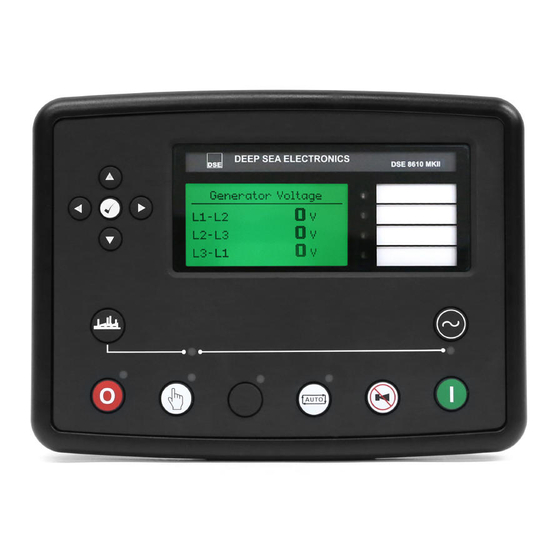
Description of Controls 4.2.3 GENERATOR Contains electrical values of the Generator, measured or derived from the module’s voltage and current inputs. Press the Instrumentation Scroll buttons scroll through the Generator parameters. Generator 50.0 Hz Generator Voltage (ph-N) Generator Voltage (ph-ph) Generator Frequency Generator Current (A) Generator Load ph-N (kW) -
Page 95: Commisioning Screens
Description of Controls 4.2.3.1 COMMISIONING SCREENS NOTE: Some of the items may be removed from the commissioning screens if they are not applicable to the module configuration. Commissioning screens are available to both aid the commissioning process and also to give additional information about the synchronising and load sharing process. -
Page 96: Synchroscope
Description of Controls 4.2.3.2 SYNCHROSCOPE Note: If the module display is showing the status page when the synchronising process begins, the module will automatically switch to the Synchroscope page. The ramp progress will also be displayed on the screen once paralleling has taken place. Initially the synchroscope display shows the difference between the bus and generator supplies. -
Page 97: Expansion
NOTE: Depending upon the module’s configuration, some display screens may be disabled. For further details of module configuration, refer to DSE Publication: 057-243 DSE8610 MKII Configuration Suite PC Software Manual. Contains measured values from various input expansion modules that are connected to the DSE module. Press the Instrumentation Scroll buttons scroll through the Expansion parameters if configured. -
Page 98: Alarms
Description of Controls 4.2.6 ALARMS When an alarm is active, the Internal Audible Alarm sounds and the Common Alarm LED, if configured, illuminates. The audible alarm is silenced by pressing the Alarm Mute / Lamp Test button. The LCD display jumps from the ‘Information page’ to display the Alarm Page Number of active alarms. -
Page 99: Ecu Alarms (Can Fault Codes / Dtc)
NOTE: For further details on connection to electronic engines, refer to DSE Publication: 057-004 Electronic Engines And DSE Wiring When connected to a suitable CAN engine, the controller displays alarm status messages from the ECU in the Alarms section of the display. -
Page 100: Event Log
Description of Controls 4.2.7 EVENT LOG NOTE: For further details of module configuration, refer to DSE Publication: 057-238 DSE8610 MKII Configuration Suite PC Software Manual. The module maintains a log of past alarms and/or selected status changes. The log size has been increased in the module over past module updates and is always subject to change. -
Page 101: Protections Disabled
Description of Controls 4.2.7.1 PROTECTIONS DISABLED NOTE: For further details on Protections Disabled, see section entitled Protections elsewhere in this manual. Configuration is possible to prevent Shutdown and Electrical Trip alarms from stopping the generator. Under such conditions the operator is informed the events were blocked. Example: Event Log Oil Pressure Low... -
Page 102: Serial Port
Description of Controls 4.2.8 SERIAL PORT 4.2.8.1 RS232 SERIAL PORT This section is included to give information about the RS232 serial port and external modem (if connected). The items displayed on this page change depending upon configuration of the module. Refer to the system supplier for further details. - Page 103 This is often a different number than the ‘voice number’ and is often called Circuit Switched Data (CSD) by the SIM provider. If the GSM modem is not purchased from DSE, ensure that it has been correctly set to operate at 9600 baud.
- Page 104 Description of Controls Modem Initialisation Sequence The modem attempts to communicate to the module If the Modem and module communicate successfully: In case of communication failure between the modem and module, the modem is automatically reset and initialisation is attempted once more: In the case of a module that is unable to communicate with the modem, the display continuously cycles between ‘Modem Reset’...
- Page 105 2 seconds The DSE MODBUS document containing register mappings inside the DSE module is available upon request from support@deepseaplc.com. Email the request along with the serial number of the DSE module to ensure the correct information is sent.
-
Page 106: Rs485 Serial Port
2 seconds. The DSE MODBUS document containing register mappings inside the DSE module is available upon request from support@deepseaplc.com. Email the request along with the serial number of the DSE module to ensure the correct information is sent. -
Page 107: About
4.2.9 ABOUT 4.2.9.1 MODULE INFORMATION Contains important information about the module and the firmware versions. This information may be asked for when contacting DSE Technical Support Department for advice. Variant: 86xx MKII About Application Version: The version of the module’s main... -
Page 108: Ethernet
Whilst in the ‘ABOUT’ section, press the Scroll Down button to access more information about the network settings. Network settings change be configured using DSE Configuration Suite Software. The module must be rebooted for the changes to take effect. •... -
Page 109: Data Logging
Description of Controls 4.2.9.3 DATA LOGGING Whilst in the ‘ABOUT’ section, press Scroll Down button to access more information about the data logging settings. Location of logged data. Displays either internal module memory or external USB memory. Data Logging Log to internal memory If data logging is active or inactive Logging active No USB drive present... -
Page 110: User Configurable Indicators
Description of Controls 4.3 USER CONFIGURABLE INDICATORS These LEDs are configured by the user to indicate any one of 100+ different functions based around the following: Indications - Monitoring of a digital input and indicating associated functioning user’s equipment - Such as Battery Charger On or Louvres Open, etc. -
Page 111: Operation
Operation 5 OPERATION NOTE: The following descriptions detail the sequences followed by a module containing the standard ‘factory configuration’. Always refer to your configuration source for the exact sequences and timers observed by any particular module in the field. 5.1 QUICKSTART GUIDE This section provides a quick start guide to the module’s operation. -
Page 112: Stopping The Engine
Operation 5.1.2 STOPPING THE ENGINE NOTE: For further details, see the section entitled Operation elsewhere in this document. Select Stop/Reset mode. The generator is stopped 057-254 ISSUE: 2 Page 112 of 188... -
Page 113: Stop/Reset Mode
When the engine has stopped and the module is in the Stop/Reset Mode , it is possible to send configuration files to the module from DSE Configuration Suite PC software and to enter the Front Panel Editor to change parameters. -
Page 114: Manual Mode
NOTE: If the unit has been configured for CAN, compatible ECU’s receives the start command via CAN. NOTE: For further details of module configuration, refer to DSE Publication: 057-238 DSE8610 MKII Configuration Suite PC Software Manual. The fuel relay is energised and the engine is cranked. -
Page 115: Engine Running
Operation 5.3.2 ENGINE RUNNING NOTE: The load transfer signal remains inactive until the generator is available. This prevents excessive wear on the engine and alternator. In Manual Mode , the generator does not synchronise and close it’s load switch unless a ‘loading request’... -
Page 116: Automatic Mode
Operation AUTOMATIC MODE NOTE: If a digital input configured to external Panel Pock is active, changing module modes is not possible. Viewing the instruments and event logs is NOT affected by Panel Lock. Auto Mode is activated by pressing the Auto Mode button. -
Page 117: Starting Sequence
5.4.2 STARTING SEQUENCE NOTE: If the unit has been configured for CAN, compatible ECU’s receive the start command via CAN and transmit the engine speed to the DSE controller. NOTE: For further details of module configuration, refer to DSE Publication: 057-238 DSE8610 MKII Configuration Suite PC Software Manual. -
Page 118: Engine Running
Operation 5.4.3 ENGINE RUNNING NOTE: The load transfer signal remains inactive until the generator is available. This prevents excessive wear on the engine and alternator. The generator synchronises to the bus and is placed on load if configured to do so. If all start requests are removed, the Stopping Sequence begins. -
Page 119: Scheduler
Up to 16 scheduled start/stop sequences can be configured to repeat on a 7-day or 28-day cycle. Scheduled runs may be on load or off load depending upon module configuration. Example: Screen capture from DSE Configuration Suite Software showing the configuration of the Exercise Scheduler. -
Page 120: Msc Compatibility Mode
= The DSE8610 MKII uses MSC link for connection to other DSE modules for ramping and load sharing. = The DSE8610 MKII is connected to a DSE123 using the MSC link to convert the MSC link to interface with Analogue... -
Page 121: Alternative Configurations
When the generator enters a stopping sequence for any reason, all the Dummy Load Control outputs de-energise at the same time as the generator load switch is signalled to open. Example screen shot of Dummy Load Control setup in the DSE Configuration Suite Page 121 of 188... -
Page 122: Load Shedding Control
When the generator enters a stopping sequence for any reason, all the Load Shedding Control outputs de-energise at the same time as the generator load switch is signalled to open. Example screen shot of Load Shedding Control setup in the DSE Configuration Suite: 057-254 ISSUE: 2... -
Page 123: Sms Control
SMS message and leave the module in the Auto Mode SMS Message 4 This SMS message will place the module into the Stop/Reset Mode 0123 4 Example screenshot of SMS Control setup in the DSE Configuration Suite: Page 123 of 188 057-254 ISSUE: 2... -
Page 124: Dead Bus Synchronising (Auto Mode)
The solution to this is a longstanding one, having being used for many decades. However modern digital communications such as the DSE MSC link has vastly improved the control and hence safety of the system operation. The solution is called Dead Bus Synchronising. Using Dead Bus Synchronising, any number of generators are able to be online and in parallel potentially within 15 seconds, depending upon applications and hardware used. -
Page 125: Operation
Operation 5.10.3 OPERATION Before the generator sets are started, their load switches are closed. As there is no AC supply the load switches must be DC controlled. Next, the alternator excitation field is disabled by isolating the supply to the AVRs. The engines are all started at the same time and allowed for the Excitation Delay timer to reach the desired operating speed. -
Page 126: Protections
Protections 6 PROTECTIONS 6.1 ALARMS When an alarm is active, the Internal Audible Alarm sounds and the Common Alarm output if configured, activates. The audible alarm is silenced by pressing the Alarm Mute / Lamp Test button. The LCD display jumps from the ‘Information page’ to display the Alarm Page Number of active alarms. -
Page 127: Protections Disabled
The system designer provides this switch (not DSE) so its location varies depending upon manufacturer, however it normally takes the form of a key operated switch to prevent inadvertent activation. Depending upon configuration, a warning alarm may be generated when the switch is operated. -
Page 128: Reset Electrical Trip
The system designer provides this switch (not DSE) so its location varies depending upon manufacturer, however it normally takes the form of a key operated switch to prevent inadvertent activation. If the DSE module is in the Manual Mode... -
Page 129: Ecu Alarms (Can Fault Codes / Dtc)
NOTE: For details on these code meanings, refer to the ECU instructions provided by the engine manufacturer, or contact the engine manufacturer for further assistance. NOTE: For further details on connection to electronic engines, refer to DSE Publication: 057-004 Electronic Engines And DSE Wiring When connected to a suitable CAN engine, the controller displays alarm status messages from the ECU in the Alarms section of the display. -
Page 130: Indications
Protections 6.2 INDICATIONS Indications are non-critical and often status conditions. They do not appear on the LCD display of the module as a text message in the Status, Event Log or Alarms pages. However, an output or LED indicator is configured to draw the operator’s attention to the event. Example: •... -
Page 131: Warning Alarms
All Warnings Are Latched causes warning alarms to latch until reset manually. This is enabled using the DSE Configuration Suite in conjunction with a compatible PC. If the module is configured for CAN and receives an “error” message from the ECU, ‘ECU Warning” is shown on the module’s display as a warning alarm. - Page 132 NOTE: Due to module configuration the alarm message that appears on the display may be different. For further details of module configuration, refer to DSE Publication: 057-238 2130 ID1 to 4 Digital Input DSE8610 MKII Configuration Suite PC Software Manual.
- Page 133 The module detected that its internal calibration has failed. The unit Calibration Fault must be sent back to DSE to be investigated and repaired. Contact DSE Technical Support for more details. The module detected that the output voltage of the charge alternator...
- Page 134 NOTE: Due to module configuration the alarm message that appears on the display may be different. For further details of module configuration, refer to DSE Publication: 057-238 Flexible Sensor A to D High DSE8610 MKII Configuration Suite PC Software Manual.
- Page 135 Protections Fault Description The module detected that the generator output frequency had not Gen Loading Frequency risen above the Generator Loading Frequency setting after the Warming Up timer had expired. The module detected that the generator output voltage had not risen Gen Loading Voltage above the Generator Loading Voltage setting after the Warming Up timer had expired.
- Page 136 Description NOTE: Due to module configuration the alarm message that appears on the display may be different. For further details of module configuration, refer to DSE Publication: 057-238 Maintenance Due DSE8610 MKII Configuration Suite PC Software Manual. The module detected that one of the configured maintenance alarms is due as its configured maintenance interval has expired.
-
Page 137: Electrical Trip Alarms
NOTE: Due to module configuration the alarm message that appears on the display may be different. For further details of module configuration, refer to DSE Publication: 057-238 2130 ID 1 to 4 Analogue Input DSE8610 MKII Configuration Suite PC Software Manual. - Page 138 NOTE: Due to module configuration the alarm message that appears on the display may be different. For further details of module configuration, refer to DSE Publication: 057-238 2130 ID1 to 4 Digital Input DSE8610 MKII Configuration Suite PC Software Manual.
- Page 139 The module detected that its internal calibration has failed. The unit Calibration Fault must be sent back to DSE to be investigated and repaired. Contact DSE Technical Support for more details. The module detected that the mains supply failed when the Combined Mains Decoupling generator was in parallel with it.
- Page 140 NOTE: Due to module configuration the alarm message that appears on the display may be different. For further details of module configuration, refer to DSE Publication: 057-238 Flexible Sensor A to D High DSE8610 MKII Configuration Suite PC Software Manual.
- Page 141 NOTE: Due to module configuration the alarm message that appears on the display may be different. For further details of module configuration, refer to DSE Publication: 057-238 Maintenance Due DSE8610 MKII Configuration Suite PC Software Manual.
- Page 142 Check all the module firmware version numbers (under About | Application Number on the modules’ displays) and MSC Old Version Unit ensure all are the latest version firmware. Use the DSE Configuration Suite Software to upgrade the firmware (Tools | Update Firmware) of the older modules.
-
Page 143: Shutdown Alarms
NOTE: Due to module configuration the alarm message that appears on the display may be different. For further details of module configuration, refer to DSE Publication: 057-238 2130 ID 1 to 4 Analogue Input DSE8610 MKII Configuration Suite PC Software Manual. - Page 144 NOTE: Due to module configuration the alarm message that appears on the display may be different. For further details of module configuration, refer to DSE Publication: 057-238 2130 ID1 to 4 Digital Input DSE8610 MKII Configuration Suite PC Software Manual.
- Page 145 The module detected that its internal calibration has failed. The unit Calibration Fault must be sent back to DSE to be investigated and repaired. Contact DSE Technical Support for more details. The module detected that the output voltage of the charge alternator...
- Page 146 Sequence Relay The module detects a condition that indicates the generator is running when the DSE module has instructed it to stop. NOTE: Due to module configuration the alarm message that appears on the display may be different. For further details...
- Page 147 Protections Fault Description The module detected that the generator output frequency had not Gen Loading Frequency risen above the Generator Loading Frequency setting after the Warming Up timer had expired. The module detected that the generator output voltage had not risen Gen Loading Voltage above the Generator Loading Voltage setting after the Warming Up timer had expired.
- Page 148 Description NOTE: Due to module configuration the alarm message that appears on the display may be different. For further details of module configuration, refer to DSE Publication: 057-238 Maintenance Due DSE8610 MKII Configuration Suite PC Software Manual. The module detected that one of the configured maintenance alarms is due as its configured maintenance interval has expired.
-
Page 149: Maintenance Alarms
The method of reset is either by: Activating an input that has been configured to Maintenance Reset Alarm 1, 2 or 3. Pressing the maintenance reset button in the DSE Configuration Suite, Maintenance section. Pressing and holding the Stop/Reset Mode button for 10 seconds on the desired Maintenance Alarm status page. - Page 150 Protections Example 3: Screen capture from DSE Configuration Suite Software showing the Maintenance Alarm Reset ‘button’ in the DSE Configuration Suite SCADA | MAINTENANCE section. Example 4: Screen capture from DSE Configuration Suite Software showing the configuration holding stop button to reset the maintenance alarm.
-
Page 151: Over Current Alarm
Protections 6.7 OVER CURRENT ALARM The Over Current Alarm combines a simple warning trip level with a fully functioning IDMT curve for thermal protection. 6.7.1 IMMEDIATE WARNING If the Immediate Warning is enabled, the controller generates a warning alarm as soon as the Trip level is reached. -
Page 152: Inverse Definite Minimum Time (Idmt) Alarm
= 2). load (when The settings shown in the example below are a screen capture of the DSE factory settings, taken from the DSE Configuration Suite PC Software for a brushless alternator. (trip point setting in current) t (time multiplier setting) These settings provide for normal running of the generator up to 100% full load. -
Page 153: Creating A Spreadsheet For The Over Current Idmt Curve
Protections 6.7.2.1 CREATING A SPREADSHEET FOR THE OVER CURRENT IDMT CURVE The formula used: − 1 Where: is the tripping time in seconds is the actual measured current of the most highly loaded line (L1, L2 or L3) is the delayed trip point setting in current is the time multiplier setting and also represents the tripping time in seconds at twice full = 2). - Page 154 Protections Over Current IDMT Alarm Curves 100000000 10000000 1000000 100000 10000 1000 Current as a Multiple of I Time Multiplier = 1 Time Multiplier = 18 Time Multiplier = 36 (Default Setting) Time Multiplier = 72 057-254 ISSUE: 2 Page 154 of 188...
-
Page 155: Short Circuit Idmt Alarm
The settings shown in the example below are a screen capture of the DSE factory settings, taken from the DSE Configuration Suite software. NOTE: Due to large inrush currents from certain loads, such as motors or transformers, the default settings for the Short Circuit alarm may need adjusting to compensate. -
Page 156: Creating A Spreadsheet For The Short Circuit Idmt Curve
Protections 6.8.1 CREATING A SPREADSHEET FOR THE SHORT CIRCUIT IDMT CURVE The formula used: 0.14 − 1 Where: is the tripping time in seconds (accurate to +/- 5% or +/- 50 ms (whichever is the greater)) is the actual measured current is the trip point setting in current is the time multiplier setting The equation can be simplified for addition into a spreadsheet. - Page 157 Protections Short Circuit IDMT Alarm Curves 10000 1000 0.01 Current as a Multiple of I Time Multiplier = 0.01 (Default Setting) Time Multiplier = 0.02 Time Multiplier = 0.04 Time Multiplier = 0.08 Time Multiplier = 0.16 Page 157 of 188 057-254 ISSUE: 2...
-
Page 158: Earth Fault Idmt Alarm
The settings shown in the example below are a screen capture of the DSE factory settings, taken from the DSE Configuration Suite software. (trip point setting in current) -
Page 159: Creating A Spreadsheet For The Earth Fault Idmt Curve
Protections 6.9.1 CREATING A SPREADSHEET FOR THE EARTH FAULT IDMT CURVE The formula used: 0.14 − 1 Where: is the tripping time in seconds (accurate to +/- 5% or +/- 50 ms (whichever is the greater)) is the actual measured current is the trip point setting in current is the time multiplier setting The equation can be simplified for addition into a spreadsheet. - Page 160 Protections Earth Fault IDMT Alarm Curves 100000 10000 1000 Current as a Multiple of I Time Multiplier = 0.1 (Default Setting) Time Multiplier = 0.2 Time Multiplier = 0.4 Time Multiplier = 0.8 Time Multiplier = 1.6 057-254 ISSUE: 2 Page 160 of 188...
-
Page 161: Default Current Protection Tripping Characteristics
Protections 6.10 DEFAULT CURRENT PROTECTION TRIPPING CHARACTERISTICS The graph on the following page shows the default settings for the IDMT tripping curves for the Over Current, Short Circuit and Earth Fault protections. The default setting for the Over Current alarm allows for an overload of an alternator to the limits of the Typical Brushless Alternator whereby 110% overload is permitted for 1 hour or 200% overload is permitted for 36 seconds. - Page 162 Protections DSE Default Configratuion of Over Current, Short Circuit & Earth Fault IDMT Alarm Curves 100000000 10000000 1000000 100000 10000 1000 0.01 Current as a Multiplier of The Full Load Current Rating Over Circuit IDMT Trip Curve with Time Multiplier = 36, Trip Point = 100% (Default Settings) Short Circuit IDMT Trip Curve with Time Multiplier = 0.01, Trip Point = 200% (Default Settings)
-
Page 163: Front Panel Configuration
This configuration mode allows the operator to fully configure the module through its display without the use of the DSE Configuration Suite PC Software. Use the module’s facia buttons to traverse the menu and make value changes to the parameters:... -
Page 164: Main Configuration Edtior
7.1.2 ENTERING PIN NOTE: The PIN is not set by DSE when the module leaves the factory. If the module has a PIN code set, the generator supplier has entered this. Contact the generator supplier if the code is required. If the code has been ‘lost’ or ‘forgotten’, the module must be returned to the DSE factory to have the PIN removed. -
Page 165: Editing A Parameter
Front Panel Configuration 7.1.3 EDITING A PARAMETER NOTE: Pressing and holding the Menu Navigation buttons provides the auto-repeat functionality. Values can be changed quickly by holding the navigation buttons for a prolonged period of time. • Press the Right or Left buttons to cycle to the section to view/change. -
Page 166: Adjustable Parameters
Front Panel Configuration 7.1.5 ADJUSTABLE PARAMETERS Section Parameter As Shown On Display Value Display Contrast Language English, Other. Current Date and Time hh:mm Engine Oil Pressure Low Shutdown 0.00 bar Oil Pressure Low Pre Alarm 0.00 bar Coolant Temp high Pre Alarm 0 ºC Coolant Temp High Shutdown 0 ºC... - Page 167 Front Panel Configuration Section Parameter As Shown On Display Value Generator Transient Delay 0 h 0 m 0 s Gen Reverse Power Delay 0 h 0 m 0 s Full kW Rating 0 kW Full kVAr Rating 0 kvar Load Ramp Rate Load Level For More Sets Load Level For Less Sets Load Demand Priority...
-
Page 168: Running' Configuration Editor
Running Editor. 7.2.2 ENTERING PIN NOTE: The PIN is not set by DSE when the module leaves the factory. If the module has a PIN code set, this has been affected by your engine supplier who should be contacted if you require the code. -
Page 169: Exiting The 'Running' Configuration Editor
Front Panel Configuration 7.2.4 EXITING THE ‘RUNNING’ CONFIGURATION EDITOR NOTE: The editor automatically exits after 5 minutes of inactivity to ensure security. • Press and hold the Tick button to exit the editor and save the changes. 7.2.5 RUNNING EDITOR PARAMETERS Section Parameter As Shown On Display Values... -
Page 170: Commisioning
For details of this procedure see section entitled Front Panel Configuration. If, despite repeated checking of the connections between the controller and the customer’s system, satisfactory operation cannot be achieved, then contact DSE Technical Support Department: Tel: +44 (0) 1723 890099 Fax: +44 (0) 1723 893303 E-mail: support@deepseaplc.com... -
Page 171: Dse 4 Steps To Successful Synchronising
Synchronising and load sharing is often considered to be a complex subject. In fact, it is very simple when broken down into smaller steps. After following the Commissioning section of this manual, the DSE 4 Steps must be followed before any parallel operation is attempted. -
Page 172: Control
Ensure that the generator is connected to a DEAD BUS BAR WITH NO LOADS connected. With the generator breaker open, set the generator to run at the Nominal Frequency without the DSE module connected to the Governor. To achieve this you will have to adjust the settings on the governor. - Page 173 Commissioning Adjustment of Governor SW2 Increase the setting of the Nominal Frequency by 2.5 Hz (52.5 Hz or 62.5 Hz) Start the generator. With the breaker open the generator will run at setting of SW1 (50 Hz or 60 Hz). 10.
-
Page 174: Determining Connections And Settings For Avrs
Ensure that the generator is connected to a DEAD BUS BAR WITH NO LOADS connected. With the generator breaker open, set the generator to run at the Nominal Voltage without the DSE module connected to the AVR. To achieve this you will have to adjust the settings on the AVR. - Page 175 Commissioning Adjustment of AVR SW2 Increase the setting of the Nominal Voltage by 10% (230 v to 253 V for example) Start the generator. With the breaker open the generator will run at setting of SW1 (230V for example). 10. Close the generator breaker onto a DEAD BUS BAR WITH NO LOADS connected. The generator voltage shall start to increase towards the new Nominal Voltage setting (253V for example) however it may not achieve this.
-
Page 176: Metering
8.2.2.1 CTS ON THE RIGHT PHASE Check to ensure that the CTs on L1, L2 & L3 are connected to their respective connection on the DSE module. This is tested by loading the generator with a purely resistive load (around 10% of the generator’s size) across the three phases. -
Page 177: Communications
Check to ensure that all the modules are connected on the MSC link and are communicating correctly. This is tested by connecting the DSE module to a PC with the DSE Configuration Suite PC Software installed and going to the SCADA | Generator | Multi-Set section. The number of Sets On The Bus must be the same as the number of DSE8x10s on the MSC link. -
Page 178: Sync Checks
DSE module sensing both sides of the breaker as in sync This is tested by starting the generator with the DSE module and ensuring the generator load switch is left open (activate an input configured for Generator Load Inhibit). Then the generator common bus is to be made live, this is achieved by starting another generator and closing its load switch. -
Page 179: Incorrectly Wired Breaker
Commissioning 8.2.4.1 INCORRECTLY WIRED BREAKER When the DSE module’s synchroscope shows the two supplies in sync, if the voltage meter shows a voltage difference the breaker is wired incorrectly. This is shown in the example below. Page 179 of 188... -
Page 180: Correctly Wired Breaker
Commissioning 8.2.4.2 CORRECTLY WIRED BREAKER When the DSE module’s synchroscope shows the two supplies in sync, if the voltage meter shows no voltage difference the breaker is wired correctly. This is shown in the example below. 057-254 ISSUE: 2 Page 180 of 188... -
Page 181: Fault Finding
Fault Finding 9 FAULT FINDING NOTE: The below fault finding is provided as a guide check-list only. As the module can be configured to provide a wide range of different features, always refer to the source of the module configuration if in doubt. 9.1 STARTING Symptom Possible Remedy... -
Page 182: Alarms
ECU Amber This indicates a fault condition detected by the engine ECU and ECU Red transmitted to the DSE controller. ECU Data Fail Indicates failure of the CAN data link to the engine ECU. Check all wiring and termination resistors (if required). -
Page 183: Synchronising & Load Sharing
Check Synchronising is enabled in the configuration suite software Generator, Synchronising section Generator will not loadshare Ensure that all the DSE Four Steps to Synchronising have been correctly completed. Check kW Share & kvar Share are enabled, check generator rating is correctly configured in the DSE configuration suite PC Sofftware and check the MSC link is connected correctly. -
Page 184: Maintenance, Spares, Repair And Servicing
In the case of malfunction, you should contact your original equipment manufacturer (OEM). 10.1 PURCHASING ADDITIONAL CONNECTOR PLUGS FROM DSE If you require additional plugs from DSE, please contact our Sales department using the part numbers below. 10.1.1 PACK OF PLUGS... -
Page 185: Purchasing Additional Sealing Gasket From Dse
NOTE: DSENet utilises an RS485 connection. Using Belden 9841 (or equivalent) cable allows for the expansion cable to be extended to a maximum of 1.2 km. DSE Stock and supply Belden 9841 cable. DSE Part Number 016-030. DSE Part Numbers Model Max No. -
Page 186: Warranty
Maintenance, Spares, Repair & Servicing 11 WARRANTY DSE Provides limited warranty to the equipment purchaser at the point of sale. For full details of any applicable warranty, refer to the original equipment supplier (OEM) 12 DISPOSAL 12.1 WEEE (WASTE ELECTRICAL AND ELECTRONIC EQUIPMENT) - Page 187 This Page is Intentionally Blank...
- Page 188 This Page is Intentionally Blank...
Need help?
Do you have a question about the 8610 MKII and is the answer not in the manual?
Questions and answers
اريد مخطط كهربائي للمحرك والمولد
The electrical schematic for the DSE 8610 MKII shows the connections between the generator, the generator control module, and the bus system. It includes circuit breakers and fuses to protect the system. The module regulates generator and bus voltages and currents. It operates with 240 VAC and 12 VDC systems and is used with generators like a 200 kW Cummins.
This answer is automatically generated