Advertisement
Advertisement
Table of Contents

Subscribe to Our Youtube Channel
Related Manuals for DSE DSE704


Summary of Contents for DSE DSE704
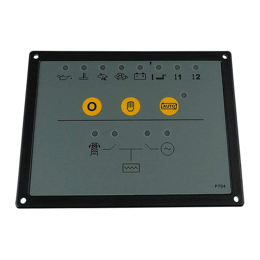
- Page 1 COMPLEX SOLUTIONS MADE SIMPLE DEEP SEA ELECTRONICS PLC DSE704 AUTOSTART CONTROL MODULE OPERATING MANUAL 057-042 704 Operating Instructions Issue 2.1 18/06/2007 11:27:00 JR - 1 - http://bestgenerator.spb.ru/?page_id=6765...
- Page 2 Website: www.deepseaplc.com DSE Model 704 Control System Operators Manual © Deep Sea Electronics Plc All rights reserved. No part of this publication may be reproduced in any material form (including photocopying or storing in any medium by electronic means or other) without the written permission of the copyright holder except in accordance with the provisions of the Copyright, Designs and Patents Act 1988.
-
Page 3: Table Of Contents
TABLE OF CONTENTS 1 DESCRIPTION OF OPERATION ............4 1.1 MANUAL MODE OPERATION ................. 4 1.2 AUTOMATIC MODE OF OPERATION ............. 5 1.3 WARNINGS ....................... 6 1.4 SHUTDOWNS ....................6 2 CONFIGURATION INSTRUCTIONS ............. 7 3 CONFIGURATION TABLES ..............8 4 TERMINAL DESCRIPTION .............. -
Page 4: Description Of Operation
1 DESCRIPTION OF OPERATION 1.1 MANUAL MODE OPERATION To initiate a start sequence in MANUAL, press the pushbutton, and the start sequence is initiated. NOTE:- There is no Start Delay in this mode of operation. If the pre-heat output option is selected this timer is then initiated, and the auxiliary output selected is energised. -
Page 5: Automatic Mode Of Operation
1.2 AUTOMATIC MODE OF OPERATION This mode is activated by pressing the pushbutton. An LED indicator beside the button confirms this action. Whether the start sequence is initiated by mains (utility) failure or by remote start input, the following sequence is followed: To allow for short term mains supply transient conditions or false remote start signals, the Start Delay timer is initiated. -
Page 6: Warnings
1.3 WARNINGS Warnings are used to warn the operator of an impending fault BATTERY CHARGE FAILURE, if the module does not detect a voltage from the warning light terminal on the auxiliary charge alternator, the icon will illuminate. (Either 8 Volts or 16 Volts depending on the configuration of Nominal DC Voltage). -
Page 7: Configuration Instructions
2 CONFIGURATION INSTRUCTIONS ♦ With the unit in Stop mode, Configuration Mode is selected by operation of a small switch on the rear, left-hand edge of the PCB. This is partially hidden to prevent accidental operation. Normal Configuration ♦ Once Configuration Mode is selected, the ‘Auto’ LED will commence rapid flashing, and all normal operation is suspended. -
Page 8: Configuration Tables
3 CONFIGURATION TABLES FUNCTIONS AND CONFIGURATION TABLE Function Value (Default in Bold) Pre-heat Timer 0 Seconds 5 Seconds 10 Seconds 15 Seconds 20 Seconds 30 Seconds 60 Seconds 180 Seconds Used to pre-heat the engine prior to cranking. The output is active for the duration of the setting, prior to cranking. Start Delay 0 Seconds 5 Seconds... - Page 9 FUNCTIONS AND CONFIGURATION TABLE Function Value (Default in Bold) Nominal Frequency 50 Hz (O/S +14% / Overshoot +24%) 60 Hz (O/S +14% / Overshoot +24%) The systems nominal frequency. Either 50 Hz or 60 Hz Nominal DC Voltage 12V DC (CF 8V) 24V DC (CF 16V) The generator battery voltage.
- Page 10 FUNCTIONS AND CONFIGURATION TABLE Function Value (Default in Bold) Auxiliary Input 1 Immediate Warning Function Close on Fault Immediate Warning Open on Fault Immediate Shutdown Close on Fault Immediate Shutdown Open on Fault Delayed Warning Close on Fault Delayed Warning Open on Fault Delayed Shutdown Close on Fault...
- Page 11 FUNCTIONS AND CONFIGURATION TABLE Function Value (Default in Bold) Auxiliary Output 1 Not used Function Pre-heat Engine Running Common Warning Common Shutdown System in Auto Common Alarm Energise to Stop Programmable output can be configured to one of the following. ♦...
-
Page 12: Terminal Description
TERMINAL DESCRIPTION DESCRIPTION CABLE NOTES SIZE DC Plant Supply Input 1.0mm Connected to plant battery negative (-ve) DC Plant Supply Input 1.0mm Connected to plant battery positive (+ve) (Recommended Fuse 2A) Fuel relay Output Used to operate the fuel relay. 1.0mm Start relay Output 1.0mm... -
Page 13: Specification
5 SPECIFICATION DC Supply: 8 Volts to 35 Volts DC Continuous. Cranking Dropouts: Able to survive 0 Volts for 50 mS, providing supply was at least 10 V before dropout and supply recovers to 5 Volts. This is achieved without the need for internal batteries. Max. -
Page 14: Solid State Outputs
To Positive supply via fuse To Fuel Solenoid Example of relay pins connected to DSE solid state output to drive a fuel solenoid. See overleaf for overall typical wiring diagram NOTE:- The Close Mains Relay should be NORMALLY CLOSED when de-energised for fail safe reasons. -
Page 15: Dimensions
7 DIMENSIONS Dimensions: 165mm x 125mm x 29mm (6.5” x 4.9” x 1.2”) Panel cutout: 149mm x 109mm (5.9” x 4.3”) Mounting Method: 4 x 4.2mm diameter holes suitable for M4 screws. 8 TYPICAL CONNECTIONS Mechanical Interlock Load Alternator Output Mains / Utility supply Electrical Interlock SSO = Solid state outputs...
Need help?
Do you have a question about the DSE704 and is the answer not in the manual?
Questions and answers
If the DSC cranks out after 3 cranks. Will the remote start be able to crank it