
Related Manuals for DSE DSE7410


Summary of Contents for DSE DSE7410
- Page 1 DEEP SEA ELECTRONICS PLC DSE7410 & DSE7420 Operator Manual Document Number: 057-161 Author: Ashley Senior DSE7410 & DSE7420 Operator Manual ISSUE: 2...
- Page 2 Deep Sea Electronics Plc at the address above. The DSE logo is a UK registered trademarks of Deep Sea Electronics PLC. Any reference to trademarked product names used within this publication is owned by their respective companies.
-
Page 3: Table Of Contents
DSE7410 & DSE7420 Operator Manual TABLE OF CONTENTS Section Page BIBLIOGRAPHY....................7 INSTALLATION INSTRUCTIONS ................... 7 TRAINING GUIDES......................7 MANUALS ........................7 THIRD PARTY DOCUMENTS ..................7 INTRODUCTION ....................8 SPECIFICATIONS .................... 9 SHORT NAMES ......................9 TERMINAL SPECIFICATION ..................9 POWER SUPPLY REQUIREMENTS ................ - Page 4 RS485 CONNECTOR ..................... 45 4.1.10 RS232 CONNECTOR ..................... 45 TYPICAL WIRING DIAGRAMS ..................46 4.2.1 DSE7410 3 PHASE, 4 WIRE WITH RESTRICTED EARTH FAULT PROTECTION 47 4.2.2 DSE7420 3 PHASE, 4 WIRE WITH RESTRICTED EARTH FAULT PROTECTION 48 ALTERNATIVE TOPOLOGIES ..................49 4.3.1 3 PHASE, 4 WIRE WITHOUT EARTH FAULT PROTECTION .......
- Page 5 DSE7410 & DSE7420 Operator Manual 5.4.9 CAN ERROR MESSAGES ..................72 VIEWING THE EVENT LOG ..................73 USER CONFIGURABLE INDICATORS ................ 74 OPERATION....................75 CONTROL ........................75 CONTROL PUSH-BUTTONS..................76 ALTERNATIVE CONFIGURATIONS ................77 DUMMY LOAD / LOAD SHEDDING CONTROL ............78 STOP MODE .........................
- Page 6 11.5 INSTRUMENTS ....................... 112 11.6 MISCELLANEOUS ....................112 MAINTENANCE, SPARES, REPAIR AND SERVICING ......113 12.1 PURCHASING ADDITIONAL CONNECTOR PLUGS FROM DSE ......113 12.1.1 PACK OF PLUGS ....................113 12.1.2 INDIVIDUAL PLUGS..................... 113 12.2 PURCHASING ADDITIONAL FIXING CLIPS FROM DSE ........113 12.3...
-
Page 7: Bibliography
Bibliography 1 BIBLIOGRAPHY This document refers to and is referred to by the following DSE publications which can be obtained from the DSE website: www.deepseaplc.com 1.1 INSTALLATION INSTRUCTIONS Installation instructions are supplied with the product in the box and are intended as a ‘quick start’... -
Page 8: Introduction
• Fully configurable inputs for use as alarms or a range of different functions. • Engine ECU interface to electronic engines. Using a PC and the DSE Configuration Suite software allows alteration of selected operational sequences, timers, alarms and operational sequences. Additionally, the module’s integral fascia configuration editor allows adjustment of a subset of this information. -
Page 9: Specifications
Minimum cable size 0.5mm² (AWG 24) Maximum cable size 2.5mm² (AWG 10) NOTE: - For purchasing additional connector plugs from DSE, please see the section entitled Maintenance, Spares, Repair and Servicing elsewhere in this document. 3.3 POWER SUPPLY REQUIREMENTS Minimum supply voltage... -
Page 10: Generator Voltage / Frequency Sensing
Specification 3.4 GENERATOR VOLTAGE / FREQUENCY SENSING Measurement type True RMS conversion Sample Rate 5KHz or better Harmonics Up to 10 or better Input Impedance 300K Ω ph-N Phase to Neutral to 333V AC (absolute maximum) (minimum required for sensing frequency Suitable for 110V to 277V nominal (±20% for under/overvoltage detection) Phase to Phase... -
Page 11: Generator Current Sensing
7VA. CT’s required in this instance is at least 7.5VA (7+0.5). NOTE: - Details for 4mm² cables are shown for reference only. The connectors on the DSE modules are only suitable for cables up to 2.5mm². NOTE: - CTs with 5A secondary windings are recommended with DSE modules. 1A CTs can be used if necessary however, the resolution of the readings is 5 times better when using 5A CTs. -
Page 12: Ct Polarity
CT PHASING Take particular care that the CTs are connected to the correct phases. For instance, ensure that the CT on phase 1 is connected to the terminal on the DSE module intended for connection to the CT for phase 1. -
Page 13: Inputs
Specification 3.6 INPUTS 3.6.1 DIGITAL INPUTS Number 11 configurable inputs Arrangement Contact between terminal and ground Low level threshold 2.1V minimum High level threshold 6.6V maximum Maximum input voltage +50V DC with respect to plant supply negative Minimum input voltage -24V DC with respect to plant supply negative Contact wetting current 7mA typical... -
Page 14: Flexible Sensor
In a failed charge situation, the voltage of this terminal is pulled down to a low voltage. It is this drop in voltage that triggers the charge failure alarm. The level at which this operates and whether this triggers a warning or shutdown alarm is configurable using the DSE Config Suite Software. -
Page 15: Outputs
DSE output drives the contactor coil, via external slave relay if required. When the DSE module requires the contactor closed, the output energises (closing the internal relay) When the DSE module requires the contactor to be open, the output is de-energised (opening the internal relay) 3.7.2.2... -
Page 16: Closing Coils
When the DSE module requires the breaker open, the output energises (closing the internal relay). For momentary (pulsed) closing signals, use a normally open relay: Generator: When the DSE module requires the breaker open, the output energises (closing the internal relay) for the period of the breaker trip pulse. 3.7.3 OUTPUTS E,F,G,H, I &... -
Page 17: Communication Ports
NOTE:- For further details for connections to CAN enabled engines and the functions available with each engine type, refer to the manual Electronic Engines and DSE Wiring. Part No. 057-004... -
Page 18: Usb Connection
The USB port is provided to give a simple means of connection between a PC and the controller. Using the DSE Configuration Suite Software, the operator is then able to control the module, starting or stopping the generator, selecting operating modes, etc. -
Page 19: Rs232
GSM modem for more remote communications. Many PCs are not fitted with an internal RS232 serial port. DSE DOES NOT recommend the use of USB to RS232 convertors but can recommend PC add-ons to provide the computer with an RS232 port. -
Page 20: Recommended External Modems
• For a data connection to a PC running DSE Configuration Suite Software, a ‘special’ CSD (Circuit Switched Data) SIM card is required that will enable the modem to answer an incoming data call. -
Page 21: Rs485
RS485 The RS485 port on the series controller supports the Modbus RTU protocol. The DSE Gencomm register table for the controller is available upon request from the DSE Technical Support Department. RS485 is used for point-to-point cable connection of more than one device (maximum 32 devices) and allows for connection to PCs, PLCs and Building Management Systems (to name just a few devices). -
Page 22: Ethernet
Specification 3.9.6 ETHERNET The module is fitted with ETHERNET socket for connection to LAN (local area networks) Description Do not connect Do not connect Do not connect Do not connect 3.9.6.1 DIRECT PC CONNECTION Requirements • DSE7400 series module • Crossover Ethernet cable (see Below) •... -
Page 23: Connection To Basic Ethernet
Specification Crossover cable wiring detail Two pairs crossed, two pairs uncrossed 10baseT/100baseTX crossover For the advanced Engineer, a crossover cable is a CAT5 cable Connection 1 (T568A) Connection 2 (T568B) with one end terminated as T568A and the other end white/green stripe white/orange stripe terminated as T568B. -
Page 24: Connection To Company Infrastructure Ethernet
NOTE:- DSE Stock a 2m (2yds) Ethernet Cable – Part number 016-137. Alternatively they can be purchased from any good PC or IT store. 3.9.6.3 CONNECTION TO COMPANY INFRASTRUCTURE ETHERNET Requirements •... -
Page 25: Connection To The Internet
NOTE:- DSE Stock a 2m (2yds) Ethernet Cable – Part number 016-137. Alternatively they can be purchased from any good PC or IT store. 3.9.6.4 CONNECTION TO THE INTERNET Requirements •... - Page 26 NOTE:- DSE Stock a 2m (2yds) Ethernet Cable – Part number 016-137. Alternatively they can be purchased from any good PC or IT store.
-
Page 27: Firewall Configuration For Internet Access
3.9.6.5 FIREWALL CONFIGURATION FOR INTERNET ACCESS As modem/routers differ enormously in their configuration, it is not possible for DSE to give a complete guide to their use with the module. However it is possible to give a description of the requirements in generic terms. -
Page 28: Dsenet® For Expansion Modules
Specification 3.10 DSENET® FOR EXPANSION MODULES DSENet® is the interconnection cable between the host controller and the expansion module(s) and must not be connect to any device other than DSE equipment designed for connection to the DSENet® Cable type Two core screened twisted pair Cable characteristic 120Ω... -
Page 29: Sounder
3.11.1 ADDING AN EXTERNAL SOUNDER TO THE APPLICATION Should an external alarm or indicator be required, this can be achieved by using the DSE Configuration Suite PC software to configure an auxiliary output for “Audible Alarm”, and by configuring an auxiliary input for “Alarm Mute” (if required). -
Page 30: Dimensions And Mounting
Specification 3.13 DIMENSIONS AND MOUNTING 3.13.1 DIMENSIONS 240.0mm x 181.1mm x 41.7mm (9.4” x 7.1” x 1.6”) 3.13.2 PANEL CUTOUT 220mm x 160mm (8.7” x 6.3”) 3.13.3 WEIGHT 0.7kg (1.4lb) -
Page 31: Fixing Clips
Specification 3.13.4 FIXING CLIPS The module is held into the panel fascia using the supplied fixing clips. • Withdraw the fixing clip screw (turn anticlockwise) until only the pointed end is protruding from the clip. • Insert the three ‘prongs’ of the fixing clip into the slots in the side of the module case. •... -
Page 32: Cable Tie Fixing Points
Specification 3.13.5 CABLE TIE FIXING POINTS Integral cable tie fixing points are included on the rear of the module’s case to aid wiring. This additionally provides strain relief to the cable loom by removing the weight of the loom from the screw connectors, thus reducing the chance of future connection failures. -
Page 33: Applicable Standards
Specification 3.14 APPLICABLE STANDARDS BS 4884-1 This document conforms to BS4884-1 1992 Specification for presentation of essential information. BS 4884-2 This document conforms to BS4884-2 1993 Guide to content BS 4884-3 This document conforms to BS4884-3 1993 Guide to presentation BS EN 60068-2-1 (Minimum -30°C (-22°F) - Page 34 Specification Continued IEEE C37.2 (Standard Electrical 50 – Instantaneous overcurrent relay Power System Device 51 – AC time overcurrent relay Function Numbers and 52 – AC circuit breaker Contact Designations) 53 – Exciter or DC generator relay 54 – Turning gear engaging device 55 –...
-
Page 35: Enclosure Classifications
Specification 3.14.1 ENCLOSURE CLASSIFICATIONS IP CLASSIFICATIONS The modules specification under BS EN 60529 Degrees of protection provided by enclosures IP65 (Front of module when module is installed into the control panel with the optional sealing gasket). IP42 (front of module when module is installed into the control panel WITHOUT being sealed to the panel) First Digit Second Digit Protection against contact and ingress of solid objects... -
Page 36: Nema Classifications
Specification 3.14.2 NEMA CLASSIFICATIONS The modules NEMA Rating (Approximate) 12 (Front of module when module is installed into the control panel with the optional sealing gasket). 2 (front of module when module is installed into the control panel WITHOUT being sealed to the panel) NOTE: - There is no direct equivalence between IP / NEMA ratings. -
Page 37: Installation
Installation – Terminal Description 4 INSTALLATION The module is designed to be mounted on the panel fascia. For dimension and mounting details, see the section entitled Specification, Dimension and mounting elsewhere in this document. 4.1 TERMINAL DESCRIPTION To aid user connection, icons are used on the rear of the module to help identify terminal functions. An example of this is shown below. -
Page 38: Dc Supply, Fuel And Start Outputs, Outputs E-J
NOTE:- Terminal 14 is not fitted to the controller. NOTE:- When the module is configured for operation with an electronic engine, FUEL and START output requirements may be different. Refer to Electronic Engines and DSE Wiring for further information. Part No. 057-004. -
Page 39: Analogue Sensor
Installation – Terminal Description 4.1.2 ANALOGUE SENSOR DESCRIPTION CABLE NOTES SIZE 0.5mm² Sensor Common Return Return feed for sensors* AWG 20 0.5mm² Oil Pressure Input Connect to Oil pressure sensor AWG 20 0.5mm² Coolant Temperature Input Connect to Coolant Temperature sensor AWG 20 0.5mm²... -
Page 40: Magnetic Pickup, Can And Expansion
NOTE:- Screened 120Ω Ω Ω Ω impedance cable specified for use with CAN must be used for the CAN link and the Multiset comms link. DSE stock and supply Belden cable 9841 which is a high quality 120Ω Ω Ω Ω impedance cable suitable for CAN use (DSE part number 016-030) NOTE:- When the module is configured for CAN operation, terminals 22, 23 &... -
Page 41: Load Switching And V1 Generator Voltage Sensing
Installation – Terminal Description 4.1.4 LOAD SWITCHING AND V1 GENERATOR VOLTAGE SENSING DESCRIPTION CABLE NOTES SIZE 1.0mm Normally configured to control mains contactor coil Output relay C AWG 18 (Recommend 10A fuse) 1.0mm Output relay C Normally configured to control mains contactor coil AWG 18 1.0mm Normally configured to control generator contactor coil... -
Page 42: Generator Current Transformers
Installation – Terminal Description 4.1.6 GENERATOR CURRENT TRANSFORMERS WARNING!:- Do not disconnect this plug when the CTs are carrying current. Disconnection will open circuit the secondary of the C.T.’s and dangerous voltages may then develop. Always ensure the CTs are not carrying current and the CTs are short circuit connected before making or breaking connections to the module. - Page 43 K is the primary of the CT that ‘points’ towards the GENERATOR or L is the primary of the CT that ‘points’ towards the LOAD s1 is the secondary of the CT that connects to the DSE Module’s input for the CT measuring (I1,I2,I3) s2 is the secondary of the CT that should be commoned with the s2 connections of all the other CTs and connected to the CT common terminal of the module.
-
Page 44: Configurable Digital Inputs
NOTES SIZE Socket for connection to PC This is a standard USB 0.5mm² with DSE Configuration Suite type A to type B AWG 20 Software connector. NOTE:- The USB connection cable between the PC and the module must not be extended beyond 5m (yards). -
Page 45: Rs485 Connector
Installation – Terminal Description 4.1.9 RS485 CONNECTOR PIN No NOTES Two core screened twisted pair cable. A (-) 120Ω impedance suitable for RS485 use. B (+) Recommended cable type - Belden 9841 Max distance 1200m (1.2km) when using Belden 9841 or direct equivalent. Location of RS485 connector Location of RS232 connector... -
Page 46: Typical Wiring Diagrams
Genset manufacturers and panel builders may use these diagrams as a starting point; however, you are referred to the completed system diagram provided by your system manufacturer for complete wiring detail. Further wiring suggestions are available in the following DSE publications, available at www.deepseaplc.com to website members. DSE PART... -
Page 47: Dse7410 3 Phase, 4 Wire With Restricted Earth Fault Protection
Installation – Typical Wiring Diagrams 4.2.1 DSE7410 3 PHASE, 4 WIRE WITH RESTRICTED EARTH FAULT PROTECTION NOTE:- Earthing the neutral conductor ‘before’ the neutral CT allows the module to read earth faults ‘after’ the CT only (Restricted to load / downstream of the CT) Earthing the neutral conductor ‘after’... -
Page 48: Dse7420 3 Phase, 4 Wire With Restricted Earth Fault Protection
Installation – Typical Wiring Diagrams 4.2.2 DSE7420 3 PHASE, 4 WIRE WITH RESTRICTED EARTH FAULT PROTECTION NOTE:- Earthing the neutral conductor ‘before’ the neutral CT allows the module to read earth faults ‘after’ the CT only (Restricted to load / downstream of the CT) Earthing the neutral conductor ‘after’... -
Page 49: Alternative Topologies
The controller is factory configured to connect to a 3 phase, 4 wire Star connected alternator. This section details connections for alternative AC topologies. Ensure to configure the controller to suit the required topology. NOTE:- Refer to DSE7400 Series Configuration Suite Manual (DSE part 057-160) for further details on configuring, monitoring and control. 4.3.1... -
Page 50: Single Phase With Restricted Earth Fault
Installation – Typical Wiring Diagrams 4.3.2 SINGLE PHASE WITH RESTRICTED EARTH FAULT NOTE:- Earthing the neutral conductor ‘before’ the neutral CT allows the module to read earth faults ‘after’ the CT only (Restricted to load / downstream of the CT) Earthing the neutral conductor ‘after’... -
Page 51: Phase (L1 & L2) 3 Wire With Restricted Earth Fault
Installation – Typical Wiring Diagrams 4.3.4 2 PHASE (L1 & L2) 3 WIRE WITH RESTRICTED EARTH FAULT NOTE:- Earthing the neutral conductor ‘before’ the neutral CT allows the module to read earth faults ‘after’ the CT only (Restricted to load / downstream of the CT) Earthing the neutral conductor ‘after’... -
Page 52: Phase (L1 & L3) 3 Wire With Restricted Earth Fault
Installation – Typical Wiring Diagrams 4.3.6 2 PHASE (L1 & L3) 3 WIRE WITH RESTRICTED EARTH FAULT NOTE:- Earthing the neutral conductor ‘before’ the neutral CT allows the module to read earth faults ‘after’ the CT only (Restricted to load / downstream of the CT) Earthing the neutral conductor ‘after’... -
Page 53: Phase 4 Wire With Unrestricted Earth Fault Measuring
Installation – Typical Wiring Diagrams 4.3.8 3 PHASE 4 WIRE WITH UNRESTRICTED EARTH FAULT MEASURING NOTE:- Unrestricted Earth Fault Protection detects earth faults in the load and in the generator. Be sure to measure the natural earth fault of the site before deciding upon an earth fault alarm trip level. -
Page 54: Ct Location
Installation – Typical Wiring Diagrams 4.3.9 CT LOCATION NOTE: CT Location is not applicable to the DSE7410 auto start controllers and is only available in DSE7420 V1.3 . There are two possible locations for the current transformers in the system: 1) Generator: The CTs are used to measure and display generator current only. - Page 55 Installation – Typical Wiring Diagrams...
-
Page 56: Earth Systems
(the battery negative connects to Earth) 4.4.2 POSITIVE EARTH When using a DSE module with a Positive Earth System (the battery positive connects to Earth), the following points must be followed: • Follow the typical wiring diagram as normal for all sections EXCEPT the earth points •... - Page 57 Installation – Typical Wiring Diagrams...
-
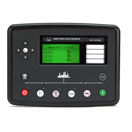
Page 58: Description Of Controls
Description Of Controls 5 DESCRIPTION OF CONTROLS 5.1 DSE7410 AUTO START CONTROL MODULE Main status and Four configurable instrumentation display Menu navigation LEDs buttons Close Generator Open Generator (manual mode only) (manual mode only) Start engine (when in manual) Select Stop... -
Page 59: Dse7420 Auto Start Control Module
Description Of Controls 5.2 DSE7420 AUTO START CONTROL MODULE Main status and Four configurable instrumentation display Menu navigation LEDs buttons Transfer to Generator Transfer to Mains (manual mode only) (manual mode only) Start engine (when in manual Select Stop or Testmode) mode Select Manual Select Test... -
Page 60: Quickstart Guide
Description Of Controls 5.3 QUICKSTART GUIDE This section provides a quick start guide to the module’s operation. 5.3.1 STARTING THE ENGINE First, select manual mode then press the Start button to crank the engine. NOTE:- For further details, see the section entitled ‘OPERATION’ elsewhere in this manual. 5.3.2 STOPPING THE ENGINE Select Stop/Reset... -
Page 61: Viewing The Instrument
If no buttons are pressed upon entering an instrumentation page, the instruments will be displayed automatically subject to the setting of the LCD Scroll Timer. The LCD Page and LCD Scroll timers are configurable using the DSE Configuration Suite Software or by using the Front Panel Editor. -
Page 62: Status
0.0pf The contents of this display may vary depending upon configuration by the generator manufacturer / supplier. The display above is achieved with the factory settings, shown below in the DSE Configuration suite software: ‘Stop Mode’ etc is displayed on the... -
Page 63: Engine
Engine ECU Link* *When connected to suitably configured and compatible engine ECU. For details of supported engines see ‘Electronic Engines and DSE wiring’ (DSE Part number 057-004). • Tier 4 engine information will also be available if used with a Tier 4 suitable engine / ECU. -
Page 64: Generator
• Generator Load (kWh, kVAh, kVArh) • Generator Phase Sequence • Generator Config (Nominals) • Generator Active Config 5.4.4 BUS (DSE7410 ONLY) • Bus Voltage (ph-N) • Bus Voltage (ph-ph) • Bus Frequency 5.4.5 MAINS (DSE7420 ONLY) NOTE: Mains current and power measurement is is only available in DSE7420 V1.3 when the CT location is selected to be the load. -
Page 65: Rs232 Serial Port
Viewing The Instrument Pages 5.4.6 RS232 SERIAL PORT This section is included to give information about the RS232 serial port and external modem (if connected). The items displayed on this page will change depending upon configuration of the module. You are referred to your system supplier for further details. - Page 66 Viewing The Instrument Pages Example 1 continued – Modem diagnostics Modem diagnostic screens are included; press when viewing the RS232 Serial Port instrument to cycle the available screens. If you are experiencing modem communication problems, this information will aid troubleshooting. Shows the state of the modem communication lines.
- Page 67 This is often a different number than the ‘voice number’ and is often called Circuit Switched Data (CSD) by the SIM provider. If the GSM modem is not purchased from DSE, ensure that it has been correctly set to operate at 9600 baud.
-
Page 68: Rs485 Serial Port
‘quiet’ on the data link. The factory settings are for the module to communicate at 19200 baud, modbus slave address 10. To use the RS485 port, ensure that ‘port usage’ is correctly set using the DSE Configuration Suite Software. -
Page 69: About
(hex) register 0304 (control mode). ControlMode=ReadRegister(10,0304,2); 5.4.8 ABOUT Contains important information about the module and the firmware versions. This information may be asked for when contacting DSE Technical Support Department for advice. • Variant (7410 or 7420) About •... -
Page 70: Ethernet
5.4.8.1 ETHERNET PAGES Whilst in the ‘ABOUT’ section, press to access more information about the network settings. Network settings change be configured using DSE Configuration Suite Software. The module must be rebooted for the changes to take effect. • Network IP Address –... -
Page 71: Data Logging Pages
Viewing The Instrument Pages 5.4.8.2 DATA LOGGING PAGES Whilst in the ‘ABOUT’ section, press to access more information about the data logging settings. Location of stored data. Data Logging Internal module memory or external Log to internal memory USB memory. Logging active No USB drive present If data logging is active or inactive... -
Page 72: Can Error Messages
NOTE: - For details on these code meanings, refer to the ECU instructions provided by the engine manufacturer, or contact the engine manufacturer for further assistance. NOTE: - For further details on connection to electronic engines please refer to Electronic engines and DSE wiring. Part No. 057-004... -
Page 73: Viewing The Event Log
Under default factory settings, the event log only includes shutdown and electrical trip alarms logged (The event log does not contain Warning alarms); however, this is configurable by the system designer using the DSE Configuration Suite software. Example showing the... -
Page 74: User Configurable Indicators
Control and Indications 5.6 USER CONFIGURABLE INDICATORS These LEDs can be configured by the user to indicate any one of 100+ different functions based around the following:- • Indications - Monitoring of a digital input and indicating associated functioning user’s equipment - Such as Battery Charger On or Louvres Open, etc. -
Page 75: Operation
Operation 6 OPERATION 6.1 CONTROL Control of the module is via push buttons mounted on the front of the module with STOP/RESET, MANUAL, TEST, AUTO, ALARM MUTE and START functions. For normal operation, these are the only controls which need to be operated. The smaller push buttons are used to access further information such as mains voltage or to change the state of the load switching devices when in manual mode. -
Page 76: Control Push-Buttons
Operation 6.2 CONTROL PUSH-BUTTONS Stop / Reset This button places the module into its Stop/Reset mode. This will clear any alarm conditions for which the triggering criteria have been removed. If the engine is running and the module is in Stop mode, the module will automatically instruct the changeover device to unload the generator (‘Close Generator’... -
Page 77: Alternative Configurations
If generator is on load, opens the generator breaker • If generator and mains are off load, closes the generator breaker. Open generator (DSE7410 only) Allows the operator to open the generator (when in Manual mode only) Transfer to mains (DSE7420 only) Operative in Manual Mode only ‘Normal’... -
Page 78: Dummy Load / Load Shedding Control
When the set enters a stopping sequence for any reason the Load Shedding control’ outputs will de- energise at the same time as the generator load switch is signalled to open. NOTE:- Refer to DSE7400 Series Configuration Suite Manual (DSE part 057-160) for further details on configuration. -
Page 79: Stop Mode
Oil pressure switch must be closed to indicate low oil pressure (MPU version only) When the engine has stopped, it is possible to send configuration files to the module from DSE Configuration Suite PC software and to enter the Front Panel Editor to change parameters. -
Page 80: Ecu Override
As the ECU is usually unpowered when the engine is not running, it must be turned on manually as follows : • Select STOP mode on the DSE controller. • Press and hold the START button to power the ECU. As the controller is in STOP mode, the engine will not be started. -
Page 81: Manual Mode
Operation 6.6 MANUAL MODE NOTE:- If a digital input configured to panel lock is active, changing module modes will not be possible. Viewing the instruments and event logs is NOT affected by panel lock. Activate Manual mode be pressing the pushbutton. -
Page 82: Engine Running
Press the Transfer to Mains button (DSE7420 only) • Press the Open Generator button (DSE7410 only) • Press the Auto Mode button to return to automatic mode. For further details of breaker control, see the section entitled “controls and indications” elsewhere in this manual. -
Page 83: Stopping Sequence
Operation 6.6.6 STOPPING SEQUENCE In manual mode the set will continue to run until either : • The stop button is pressed – The set will immediately stop • The auto button is pressed. The set will observe all auto mode start requests and stopping timers before beginning the Auto mode stopping sequence. -
Page 84: Engine Running
Operation 6.7.3 ENGINE RUNNING Once the engine is running, the Warm Up timer, if selected, begins, allowing the engine to stabilise before accepting the load. Load will be automatically transferred from the mains supply to the generator. NOTE:-The load transfer signal remains inactive until the Oil Pressure has risen. This prevents excessive wear on the engine. -
Page 85: Automatic Mode
Operation 6.8 AUTOMATIC MODE NOTE:- If a digital input configured to panel lock is active, changing module modes will not be possible. Viewing the instruments and event logs is NOT affected by panel lock. Activate auto mode be pressing the pushbutton. -
Page 86: Engine Running
Once the engine is running, the Warm Up timer, if selected, begins, allowing the engine to stabilise before accepting the load. DSE7410 - The generator will be placed on load. DSE7420 - Load will be transferred from the mains supply to the generator NOTE:-The load transfer signal remains inactive until the Oil Pressure has risen. -
Page 87: Protections
Protections 7 PROTECTIONS When an alarm is present, the Audible Alarm will sound and the Common alarm LED if configured will illuminate. The audible alarm can be silenced by pressing the Mute button The LCD display will jump from the ‘Information page’ to display the Alarm Page Number of present alarms. -
Page 88: Protections Disabled
The system designer provides this switch (not DSE) so its location will vary depending upon manufacturer, however it normally takes the form of a key operated switch to prevent inadvertent activation. Depending upon configuration, a warning alarm may be generated when the switch is operated. -
Page 89: Can Alarms
7.1.3 CAN ALARMS NOTE:- Please refer to the engine manufacturer’s documentation for ECU CAN error message information. CAN alarms are messages sent from the CAN ECU to the DSE controller and displayed as follows in the below tables. Display Reason... -
Page 90: Indications
Protections 7.2 INDICATIONS Indications are non-critical and often status conditions. They do not appear on the LCD of the module as a text message. However, an output or LED indicator can be configured to draw the operator’s attention to the event. Example •... -
Page 91: Warnings
The engine ECU has detected a warning alarm and has informed the CAN ECU ERROR DSE module of this situation. The exact error is also indicated on the module’s display. kW OVERLOAD The measured Total kW is above the setting of the kW overload... -
Page 92: High Current Warning Alarm
DISABLED module display; The alarm text is displayed but the engine will continue to run. This is ‘logged’ by the module to allow DSE Technical Staff to check if the protections have been disabled on the module at any time. -
Page 93: Shutdowns
Protections 7.5 SHUTDOWNS NOTE:- Shutdown and Electrical Trip alarms can be disabled by user configuration. See the section entitled Protections Disabled elsewhere in this document. Shutdowns are latching alarms and stop the Generator. Clear the alarm and remove the fault then press Stop/Reset to reset the module. - Page 94 ECU SHUTDOWN The engine ECU has detected a shutdown alarm and has informed the DSE module of this situation. The exact error is also indicated on the module’s display. The measured Total kW is above the setting of the kW...
-
Page 95: Electrical Trips
Protections Disabled will appear on the module display; The DISABLED alarm text is displayed but the engine will continue to run. This is ‘logged’ by the module to allow DSE Technical Staff to check if the protections have been disabled on the module at any time. GENERATOR UNDER... -
Page 96: High Current Shutdown / Electrical Trip Alarm
Protections 7.7 HIGH CURRENT SHUTDOWN / ELECTRICAL TRIP ALARM The overcurrent alarm combines a simple warning trip level with a fully functioning IDMT curve for thermal protection. 7.7.1 IMMEDIATE WARNING If the Immediate Warning is enabled, the controller generates a warning alarm as soon as the Trip level is reached. - Page 97 Protections Factory settings for the IDMT Alarm when used on a brushless alternator are as follows (screen capture from the DSE Configuration Suite PC software : (Trip setting value) (time multiplier) These settings provide for normal running of the generator up to 100% full load. If full load is surpassed, the Immediate Warning alarm is triggered, the set continues to run.
- Page 98 Protections...
-
Page 99: Earth Fault Shutdown / Electrical Trip Alarm
I is the actual earth current measured (Trip setting value) is the trip setting value K (time multiplier setting) The settings shown in the example above are a screen capture of the DSE factory settings, taken from the DSE Configuration Suite software. -
Page 100: Short Circuit Alarm
I is the actual current measured (Trip setting Is is the trip setting value value) K (time multiplier setting) The settings shown in the example above are a screen capture of the DSE factory settings, taken from the DSE Configuration Suite software. -
Page 101: Maintenance Alarm
Screen capture from DSE Configuration Suite Software showing the configuration of a digital input for Reset Maintenance Alarm 1. Example 3 Screen capture from DSE Configuration Suite Software showing the Maintenance Alarm Reset ‘button’ in the DSE Configuration Suite SCADA | MAINTENANCE section. -
Page 102: Scheduler
Up to 16 scheduled start/stop sequences can be configured to repeat on a 7-day or 28-day cycle. Scheduled runs may be on load or off load depending upon module configuration. Example Screen capture from DSE Configuration Suite Software showing the configuration of the Exercise Scheduler. In this example the set will start at 09:00... -
Page 103: Front Panel Configuration
Front Panel Configuration 9 FRONT PANEL CONFIGURATION This configuration mode allows the operator limited customising of the way the module operates. Use the module’s navigation buttons to traverse the menu and make value changes to the parameters: Increase value / next item Previous page Decrease value / next item... -
Page 104: Accessing The Main Front Panel Configuration Editor
PIN code set, this has been affected by your generator supplier who should be contacted if you require the code. If the code has been ‘lost’ or ‘forgotten’, the module must be returned to the DSE factory to have the module’s code removed. A charge will be made for this procedure. -
Page 105: Editing A Parameter
Front Panel Configuration 9.1.1 EDITING A PARAMETER Enter the editor as described above. Press the (left) or (right) buttons to cycle to the section you wish to view/change. Press the (up or down) buttons to select the parameter you wish to view/change within the currently selected section. -
Page 106: Adjustable Parameters
Front Panel Configuration 9.2 ADJUSTABLE PARAMETERS Front Panel Configuration Editor. For descriptions of the parameters, you are referred to The DSE series Configuration Suite Manual, DSE Part 057-160. Section Parameter As Shown On Display Values Display Contrast Language English, others. -
Page 107: Accessing The 'Running' Configuration Editor
Front Panel Configuration 9.3 ACCESSING THE ‘RUNNING’ CONFIGURATION EDITOR The ‘running’ editor can be entered while the engine is running. All protections remain active if the engine is running while the running editor is entered. Press and hold the button to enter the running editor. 9.3.1 EDITING A PARAMETER Enter the editor as described above. -
Page 108: Commissioning
Commissioning and Fault Finding 10 COMMISSIONING 10.1 PRE-COMMISSIONING Before the system is started, it is recommended that the following checks are made:- • The unit is adequately cooled and all the wiring to the module is of a standard and rating compatible with the system. -
Page 109: Fault Finding
Commissioning and Fault Finding 11 FAULT FINDING 11.1 STARTING SYMPTOM POSSIBLE REMEDY Unit is inoperative Check the battery and wiring to the unit. Check the DC supply. Check the DC fuse. Read/Write configuration does not operate Unit shuts down Check DC supply voltage is not above 35 Volts or below 9 Volts Check the operating temperature is not above 70°C. -
Page 110: Alarms
CAN ECU WARNING This indicates a fault condition detected by the engine ECU and CAN ECU SHUTDOWN transmitted to the DSE controller. Press the RIGHT ARROW button to view the engine diagnostic code and consult the engine manufacturer’s documentation. CAN DATA FAIL Indicates failure of the CAN data link to the engine ECU. -
Page 111: Communications
Ethernet rated cable is used • Direct to PC connection requires a CROSSOVER cable. • Check the IP address of the DSE controller is correct • Check the PC is not set to obtain IP address automatically • Check PC firewall will allow traffic on the configured port. -
Page 112: Instruments
Commissioning and Fault Finding 11.5 INSTRUMENTS SYMPTOM POSSIBLE REMEDY Inaccurate generator Check that the CT primary, CT secondary and VT ratio settings are measurements on controller correct for the application. display Check that the CTs are wired correctly with regards to the direction of current flow (p1,p2 and s1,s2) and additionally ensure that CTs are connected to the correct phase (errors will occur if CT1 is connected to phase 2). -
Page 113: Maintenance, Spares, Repair And Servicing
In the case of malfunction, you should contact your original equipment manufacturer (OEM). 12.1 PURCHASING ADDITIONAL CONNECTOR PLUGS FROM DSE If you require additional plugs from DSE, please contact our Sales department using the part numbers below. 12.1.1 PACK OF PLUGS... -
Page 114: Dsenet Expansion Modules
NOTE:- DSENet® utilises an RS485 connection. Using Belden 9841 (or equivalent) cable allows for the expansion cable to be extended to a maximum of 1.2km. DSE Stock and supply Belden 9841 cable. DSE Part Number 016-030. DSE Part Numbers Max No. -
Page 115: Warranty
Disposal 13 WARRANTY DSE provides limited warranty to the equipment purchaser at the point of sale. For full details of any applicable warranty, you are referred to your original equipment supplier (OEM). 14 DISPOSAL 14.1 WEEE (WASTE ELECTRICAL AND ELECTRONIC EQUIPMENT) - Page 116 This page is intentionally left blank...
-
Page 117: Disposal
Disposal This page is intentionally left blank... - Page 118 TYPICAL WIRING DIAGRAM D E E P S E A E L E C T R O N I C S 053-085 A larger diagram is available in the operators manual. 7 4 1 0 I N S T A L L A T I O N I N S T R U C T I O N S ISSUE 3 ACCESSING THE FRONT PANEL CONFIGURATION EDITOR.
- Page 119 ADJUSTABLE PARAMETERS Front Panel Configuration Editor (continued) Front Panel Configuration Editor (Factory default settings are shown in bold italicised text) Section Parameter as shown on display Values Section Parameter as shown on display Values Scheduler Scheduler Active, Inactive Active , Inactive (Only Available When Display Contrast Schedule On Load...
- Page 120 Fault condition notification to • Independent earth fault trip DIMENSIONS OVERALL a designated PC • Fully configurable via DSE 240 mm x 181 mm x 42 mm • Front panel mounting Configuration Suite PC software 9.4” x 6.8” x 1.6” •...
- Page 121 Industrial Environment FEATURES ELECTRICAL SAFETY BS EN 60950 Safety of Information Technology Equipment, including Electrical Business Equipment The DSE7410 is an Auto Start The DSE7400 Series modules are TEMPERATURE BS EN 60068-2-1 Control Module and the DSE7420 compatible with electronic (CAN)
Need help?
Do you have a question about the DSE7410 and is the answer not in the manual?
Questions and answers