Sign In
Upload
Manuals
Brands
DSE Manuals
Control Unit
8610 MKII
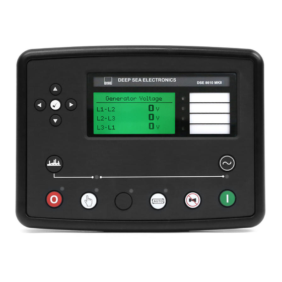
DSE 8610 MKII Sharing Control Module Manuals
Manuals and User Guides for DSE 8610 MKII Sharing Control Module. We have
1
DSE 8610 MKII Sharing Control Module manual available for free PDF download: Operator's Manual
DSE 8610 MKII Operator's Manual (188 pages)
Brand:
DSE
| Category:
Control Unit
| Size: 2 MB
Table of Contents
Table of Contents
3
1 Introduction
8
Clarification of Notation
9
Glossary of Terms
9
Bibliography
11
Installation Instructions
11
Manuals
11
Training Guides
12
Third Party Documents
12
2 Specification
13
Operating Temperature
13
Screen Heater Operation
13
Requirements for Ul
13
Terminal Specification
14
Power Supply Requirements
14
Module Supply Instrumentation Display
14
Voltage & Frequency Sensing
15
Current Sensing
15
Va Rating of the Cts
16
Ct Polarity
17
Ct Phasing
17
Ct Class
17
Inputs
18
Digital Inputs
18
Emergency Stop
18
Analogue Inputs
19
Analogue Input a
19
Analogue Input B, C & D
20
Charge Fail Input
21
Magnetic Pick-Up
21
Outputs
22
DC Outputs a & B (Fuel & Start)
22
Configurable Volt-Free Relay Outputs C & D
22
Configurable DC Outputs E, F, G, H, I, J, K & L
22
Governor Control Output
22
Avr Control Output
22
Communication Ports
23
Communication Port Usage
24
Usb Slave Port (Pc Configuration)
24
Usb Host Port (Data Logging)
24
Rs232 Port
25
Recommended External Modems
25
Recommended Pc Rs232 Serial Port Add-Ons
26
Rs485 Port
27
Cable Specification
27
Recommended Pc Rs485 Serial Port Add-Ons
28
Rs485 Used for Modbus Engine Connection
29
Ethernet Port
30
Direct Pc Connection
31
Connection to Basic Ethernet
32
Connection to Company Ethernet Infrastructure
33
Connection to the Internet
34
Firewall Configuration for Internet Access
35
Msc (Multi-Set Communications) Link
36
Can Port
37
Ecu Port (J1939)
37
Dsenet (Expansion Modules)
38
Dsenet Used for Modbus Engine Connection
39
Sounder
40
Adding an External Sounder
40
Accumulated Instrumentation
40
Dimensions and Mounting
41
Dimensions
41
Panel Cutout
41
Weight
41
Fixing Clips
42
Cable Tie Fixing Points
43
Silicon Sealing Gasket
43
Applicable Standards
44
Enclosure Classifications
46
Ip Classifications
46
Nema Classifications
46
3 Installation
47
User Connections
47
Connection Descriptions
48
DC Supply, E-Stop Input, DC Outputs & Charge Fail Input
48
Analogue Sensor Inputs & Can
49
Mpu, Ecu, Msc & Dsenet
50
Output C & D & V1 (Generator) Voltage & Frequency Sensing
51
V2 (Bus) Voltage & Frequency Sensing
51
Current Transformers
52
Ct Connections
53
Digital Inputs
53
Rs485
54
Rs232
55
Usb Slave (Pc Configuration) Connector
56
Usb Host (Data Logging) Connector
56
Typical Wiring Diagram
57
Phase 4 Wire) with Restricted Earth Fault
58
Earth Systems
59
Negative Earth
59
Positive Earth
59
Floating Earth
59
Typical Arrangement of Dsenet
60
Typical Arrangement of Msc Link
61
Alternate Topology Wiring Diagrams
62
Single Phase (L1 & N) 2 Wire with Restricted Earth Fault
62
Single Phase (L1 & N) 2 Wire Without Earth Fault
63
Single Phase (L1 & L2) 3 Wire with Restricted Earth Fault
64
Single Phase (L1 & L2) 3 Wire Without Earth Fault
65
Single Phase (L1 & L3) 3 Wire with Restricted Earth Fault
66
Single Phase (L1 & L3) 3 Wire Without Earth Fault
67
Phase (L1 & L2) 3 Wire with Restricted Earth Fault
68
Phase (L1 & L2) 3 Wire Without Earth Fault
69
Phase (L1 & L3) 3 Wire with Restricted Earth Fault
70
Phase (L1 & L3) 3 Wire Without Earth Fault
71
Phase 3 Wire Detla Without Earth Fault
72
Phase 4 Wire Without Earth Fault
73
Phase 4 Wire with Restricted Earth Fault
74
Phase 4 Wire with Unrestricted Earth Fault
75
Typical Single Line Application Drawings
76
Multi Generators for Prime Power
76
Multi Generators for Prime Power with Bus Couplers
77
Multi Generators with Single Synchronising Transfer Switch
78
Multi Generators with Two Synchronising Transfer Switches
79
Multi Generators & Synchronising Transfer Switches
80
Multi Generators & Transfer Switches with Bus Coupler
81
Single Generator Exporting (Base Loading) Power
82
Multi Generators Exporting (Base Loading) Power
83
4 Description of Controls
84
Control Push Buttons
86
Viewing the Instrument
88
Status
89
Generator Locked out
90
Waiting for Generator
90
Engine
91
Manual Fuel Pump Control
92
Dpf Regeneration Lamps
93
Generator
94
Commisioning Screens
95
Synchroscope
96
Bus
96
Expansion
97
Alarms
98
Ecu Alarms (Can Fault Codes / Dtc)
99
Event Log
100
Protections Disabled
101
Reset Electrical Trip
101
Serial Port
102
Rs232 Serial Port
102
Rs485 Serial Port
106
About
107
Module Information
107
Ethernet
108
Data Logging
109
User Configurable Indicators
110
5 Operation
111
Quickstart Guide
111
Starting the Engine
111
Stopping the Engine
112
Stop/Reset Mode
113
Ecu Override
113
Manual Mode
114
Starting Sequence
114
Engine Running
115
Stopping Sequence
115
Automatic Mode
116
Waiting in Auto Mode
116
Starting Sequence
117
Engine Running
118
Stopping Sequence
118
Scheduler
119
Stop Mode
119
Manual Mode
119
Auto Mode
119
Msc Compatibility Mode
120
Alternative Configurations
121
Dummy Load / Load Shedding Control
121
Dummy Load Control
121
Load Shedding Control
122
Sms Control
123
Dead Bus Synchronising (Auto Mode)
124
Benefit of System
124
Hardware Requirements
124
Operation
125
6 Protections
126
Protections Disabled
127
Reset Electrical Trip
128
Ecu Alarms (Can Fault Codes / Dtc)
129
Indications
130
Warning Alarms
131
Electrical Trip Alarms
137
Shutdown Alarms
143
Maintenance Alarms
149
Over Current Alarm
151
Inverse Definite Minimum Time (Idmt) Alarm
152
Creating a Spreadsheet for the over Current Idmt Curve
153
Short Circuit Idmt Alarm
155
Creating a Spreadsheet for the Short Circuit Idmt Curve
156
Earth Fault Idmt Alarm
158
Creating a Spreadsheet for the Earth Fault Idmt Curve
159
Default Current Protection Tripping Characteristics
161
7 Front Panel Configuration
163
Main Configuration Edtior
164
Editing a Parameter
165
Adjustable Parameters
166
Running' Configuration Editor
168
Exiting the 'Running' Configuration Editor
169
8 Commisioning
170
Dse 4 Steps to Successful Synchronising
171
Control
172
Determining Connections and Settings for Avrs
174
Metering
176
Communications
177
Sync Checks
178
Incorrectly Wired Breaker
179
Correctly Wired Breaker
180
9 Fault Finding
181
Alarms
182
Synchronising & Load Sharing
183
10 Maintenance, Spares, Repair and Servicing
184
Purchasing Additional Sealing Gasket from Dse
185
11 Warranty
186
Advertisement
Advertisement
Related Products
DSE 8860
DSE 4110
DSE 5210
DSE 53 Series
DSE 560
DSE DSE 6120
DSE DSE2157
DSE DSE5310
DSE DSE704
DSE Categories
Security Camera
Digital Camera
Controller
Control Unit
DVR
More DSE Manuals
Login
Sign In
OR
Sign in with Facebook
Sign in with Google
Upload manual
Upload from disk
Upload from URL