Advertisement
Quick Links
053-034
ISSUE 2
Introduction
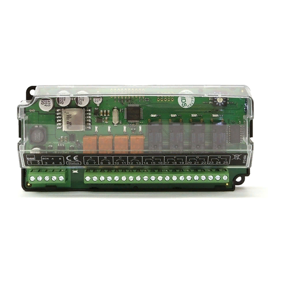
DSE2157 relay expansion module is used in conjunction with the DSE7000 series controllers to
provide additional relay output functionality. The relay outputs are configured in the 'host controller',
the DSE2157 module is not itself configured apart from the 'ID switch' detailed below.
For further details on configuring the 'host controller' you are referred to the relevant configuration
software manual.
Controls and indications
Power on /
Link lost LED
LED Indications
Function
Power on / Link lost
Status 1-8
ID switch
The rotary ID switch is used to select the 'ID' of the 2157 expansion module as the host controller is
capable of giving instructions to a number of 2157 expansion modules at the same time (consult
relevant modules instructions for further details on number of supported expansion units).
The enclosure cover must be unclipped and removed to gain access to the switch. The switch should
be operated using a small screwdriver and set to match the required ID.
NOTE : The ID must be a unique number, different from the ID of any other 2157 module
connected to the host controller.
If two or more 2157 controllers are required to 'mimic' each other then they should be
configured with different IDs, and both configured the same in the host controller.
NOTE : The selection of the ID of other types of expansion modules WILL NOT interfere/clash
with the ID of the 2548. For instance if the 2548 is set to ID 4, it is acceptable to have a different
type of expansion module (for instance 2130) set to ID 4 also.
D E E P S E A E L E C T R O N I C S
2157 Output Expansion Installation Instructions
Colour
Action
RED
Steady when DC supply is connected and data is being received
from the host controller.
Flashing when the DC supply is connected and the data
connection to the host controller is not operating.
RED
Lit when the corresponding relay is active
ID Switch
8 x Status LED
(1 LED per
relay)
Advertisement

Related Manuals for DSE DSE2157


Summary of Contents for DSE DSE2157
- Page 1 2157 Output Expansion Installation Instructions Introduction DSE2157 relay expansion module is used in conjunction with the DSE7000 series controllers to provide additional relay output functionality. The relay outputs are configured in the ‘host controller’, the DSE2157 module is not itself configured apart from the ‘ID switch’ detailed below.
- Page 2 Typical wiring diagrams NOTE : Configuration of the outputs is performed in the host controller. Dimensions Overall size 164.6mm x 76.4mm x 48.9mm (6.48” x 3.01” x 1.93”) Mounting type DIN rail or chassis mounting Din rail type EN 50022 35mm type only Mounting holes M4 clearance Mounting hole centres...
- Page 3 COMPLEX SOLUTIONS MADE SIMPLE DEEP SEA ELECTRONICS ® DSEEXTRA DSE2157 relay output expansion module 057-083 Author : Anthony Manton...
- Page 4 Typeface : The typeface used in this document is Arial. Care should be taken not to mistake the upper case letter I with the numeral 1. The numeral 1 has a top serif to avoid this confusion. 057-083 Issue 1 DSE2157 relay output expansion operator manual...
-
Page 5: Table Of Contents
FAULT DIAGNOSIS ..................10 MAINTENANCE, SPARES, REPAIR AND SERVICING ........10 WARRANTY ....................10 DISPOSAL ...................... 10 11.1 WEEE (WASTE ELECTRICAL AND ELECTRONIC EQUIPMENT) ......... 10 11.2 ROHS (RESTRICTION OF HAZARDOUS SUBSTANCES ..........10 057-083 Issue 1 DSE2157 relay output expansion operator manual... -
Page 6: Bibliography
DSE2157 relay output expansion module 1 BIBLIOGRAPHY This document refers to and is reffered to by the following DSE publications which can be obtained from the DSE website www.deepseaplc.com DSE PART DESCRIPTION 057-074 7000 series operators manual 057-077 7000 series configuration software manual... -
Page 7: Specifications
3.2 DSENET® DSEnet is the interconnection cable between the host controller and the expansion module(s) and must not be connect to any device other than DSE equipment designed for connection to the DSEnet. Cable type Two core screened twisted pair Cable characteristic impedance 120Ω... -
Page 8: Outputs
UL508 enclosure type 1 (indoor use only) NEMA rating In line with our policy of continual development, Deep Sea Electronics, reserve the right to change specification without notice. 057-083 Issue 1 DSE2157 relay output expansion operator manual... -
Page 9: Installation
NOTE : Normally open / normally closed refers to the contacts when the DC supply is removed from the module. The powered up state of the module depends upon configuration of the connected ‘host module’. 057-083 Issue 1 DSE2157 relay output expansion operator manual... -
Page 10: Typical Wiring Diagram
DSE2157 relay output expansion module 6 TYPICAL WIRING DIAGRAM 057-083 Issue 1 DSE2157 relay output expansion operator manual... -
Page 11: Controls And Indications
If two or more 2157 controllers are required to ‘mimic’ each other then they should be configured with different IDs, and both configured the same in the host controller. 057-083 Issue 1 DSE2157 relay output expansion operator manual... -
Page 12: Fault Diagnosis
9 MAINTENANCE, SPARES, REPAIR AND SERVICING The DSE2157 is designed to be Fit and Forget. As such, there are no user serviceable parts. In the case of malfunction you should contact your original equipment supplier (OEM). - Page 13 ® DSEGenset DSE2157 DSENET OUTPUT EXPANSION MODULE ® HOST MODULE (1) DSENET DC POWER ® EXPANSION SUPPLY 8-35V COMPATIBLE WITH DSE7310/20, DSE8610/60/80 & DSE8710/60 DSE2157 DSENET ® HOST MODULE 2157 2130 2510/20 2548 OTHER VOLT-FREE NORMALLY OPEN OUTPUTS VOLT-FREE CHANGE OVER OUTPUTS...
- Page 14 Ab/Ae Cold Test -30 convenient fixing into a panel. BS EN 60068-2-2 Bb/Be Dry Heat +70 A maximum of 10 DSE2157’s can be connected to an individual module at The module will work up to 1 KM VIBRATION any one time. All outputs (0.6miles) from the host control...
- Page 15 ID SWITCH • Power On/Link Lost LED ID The rotary ID switch is used to SWITCH select the address of the DSE2157 • 10 expansion modules can be expansion module, as the host connected to 1 host controller at control module is capable of giving...
Need help?
Do you have a question about the DSE2157 and is the answer not in the manual?
Questions and answers