Table of Contents
Advertisement
Available languages
Available languages
Operator's Manual
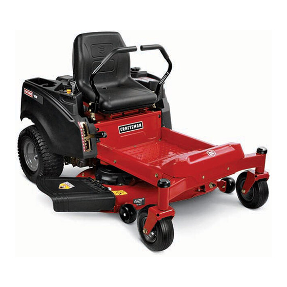
Z6000 SERIES
ZERO-TURN RIDER
Model Nos. 247.20411* & 247.27775*
* -- Last digit of model number varies
Safe Operation Practices .................................................2
Slope Gauge ...................................................................6
Assembly .......................................................................7
Operation ..................................................................... 11
Service And Maintenance ..............................................20
NOTE: This Operator's Manual covers several models. Features may vary by model. Not all features in this manual are applicable to all models and the model
depicted may differ from yours.
This product has a low emission engine which operates differently
from previously built engines. Before you start the engine, read
and understand this Craftsman Operator's Manual and the Engine
Operator's Manual.
CAUTION
Before using this equipment,
read this manual and follow
all safety rules and operating
instructions.
Sears Brands Management Corporation, Hoffman Estates, IL 60179 U.S.A.
Visit our website: www.craftsman.com
Off-Season Storage .......................................................30
Troubleshooting ........................................................... 31
Español ........................................................................ 33
Warranty/Service ....................... See Separate Supplement
For answers to your questions about
these products, call:
1-888-331-4569
Craftsman Customer Hot Line
Form No. 769-11975A
(December 7, 2016)
Advertisement
Table of Contents

Related Manuals for Craftsman Z6000 SERIES


Summary of Contents for Craftsman Z6000 SERIES
- Page 1 This product has a low emission engine which operates differently from previously built engines. Before you start the engine, read and understand this Craftsman Operator’s Manual and the Engine Operator’s Manual. For answers to your questions about...
- Page 2 SAFETY INSTRUCTIONS WARNING DANGER This symbol points out important safety instructions which, if not This machine was built to be operated according to the safe operation followed, could endanger the personal safety and/or property of practices in this manual. As with any type of power equipment, yourself and others.
- Page 3 SAFETY INSTRUCTIONS CHILDREN • Your machine is designed to cut normal residential grass of a height no more than 10”. Do not attempt to mow through unusually tall, dry grass (e.g., Tragic accidents can occur if the operator is not alert to the presence of children. pasture) or piles of dry leaves.
- Page 4 SAFETY INSTRUCTIONS • Keep the nozzle in contact with the rim of the fuel tank or container opening • Grass catcher components and the discharge cover are subject to wear at all times until fueling is complete. Do not use a nozzle lock-open device. and damage which could expose moving parts or allow objects to be thrown.
- Page 5 SAFETY INSTRUCTIONS SAFETY SYMBOLS This page depicts and describes safety symbols that may appear on this product. Read, understand, and follow all instructions on the machine before attempting to assemble and operate. Symbol Description READ THE OPERATOR’S MANUAL(S) Read, understand, and follow all instructions in the manual(s) before attempting to assemble and operate DANGER —...
- Page 6 SLOPE GAUGE...
- Page 7 ASSEMBLY Set-Up Position Drive Control levers The drive control levers of the riding mower are lowered for shipping purposes. NOTE: Remove the deck wash system nozzle adapter and oil drain tube from the The flange lock nuts, hex screws, and flat washers that normally secure the control manual bag and store for future use.
- Page 8 ASSEMBLY Connecting the Battery Cables Lower Deck Discharge Chute Deflector WARNING WARNING Battery posts, terminals, and related accessories contain lead and lead Never operate the mower deck without the chute deflector installed and in compounds, chemicals known to the State of California to cause cancer and the down position.
- Page 9 ASSEMBLY Adjusting the Gauge Wheels Adjusting the Seat NOTE: Be sure to push the excess wire from the wire harness into the seat box hole WARNING prior to lowering the seat. Keep hands and feet away from the discharge opening of the cutting deck. To adjust the position of the seat, pivot the seat forward and locate the clamp knobs on the front portion of the seat pan.
- Page 10 ASSEMBLY Adding Fuel WARNING Use extreme care when handling gasoline. Gasoline is extremely flammable and the vapors are explosive. Never fuel the riding mower indoors or while the engine is hot or running. Extinguish cigarettes, cigars, pipes and other sources of ignition. Be sure engine is outdoors and in a well-ventilated area.
- Page 11 OPERATION Deck Lift Handle Deck Height Index LH Drive RH Drive Throttle/Choke Control Control Lever Control Lever LCD Service Minder & Hour Meter Fuel Level Window PTO Switch Ignition Module Cup Holder Fuel Tank Cap Storage Tray RH Transmission Bypass Rod LH Transmission Bypass Rod Figure 7 RH and LH Drive Control Levers...
- Page 12 OPERATION Ignition Module Push the cap downward on the fuel tank fill neck and turn clockwise until it clicks to tighten. Always re-install the fuel cap tightly onto the fuel tank after removing WARNING WARNING Never leave a running machine unattended. Always disengage PTO, set Never fill the fuel tank when the engine is running.
- Page 13 OPERATION Before Operating Your Riding mower Throttle/Choke Control • Before you operate the riding mower, study this manual carefully to familiarize The throttle/choke control is located on the RH console to the right of the operator’s seat. When set in a given position, a uniform engine speed will yourself with the operation of all the instruments and controls.
- Page 14 OPERATION Starting the Engine Be sure the battery is in good condition. Also, a warm battery has much more starting capacity than a cold battery. WARNING Use fresh winter grade fuel. Winter grade gasoline has higher volatility to This riding mower is equipped with a safety interlock system designed for improve starting.
- Page 15 OPERATION Driving the Riding mower Slowly and evenly move both drive control levers forward. The riding mower will start to move forward. See “Figure 10”. WARNING Faster Avoid sudden starts, excessive speed and sudden stops. Driving Forward Adjust the operator’s seat to the most comfortable position that allows you to operate the controls.
- Page 16 OPERATION Driving the Riding mower In Reverse To turn to the left, move the left drive control lever rearward of the right lever. See “Figure 11”. WARNING Forward Left Turn Always look behind and down on both sides of the riding mower before backing up.
- Page 17 OPERATION Reverse Caution Mode (If equipped) To turn to the left while traveling in reverse, move the left drive control lever forward of the right lever. See “Figure 14”. The REVERSE CAUTION MODE position of the key switch module allows the tractor to be operated in reverse with the blades (PTO) engaged.
- Page 18 OPERATION Stopping the Riding mower Executing a Zero Turn Move both drive control levers to the neutral position (parking brake on) to WARNING stop the motion of the riding mower. When executing a zero turn, the riding mower MUST BE STOPPED. Push the PTO switch downward to the DISENGAGED position.
- Page 19 OPERATION Using the Mower Deck WARNING Make certain the area to be mowed is free of debris, sticks, stones, wire or other objects that can be thrown by the rotating blades. NOTE: Do not engage the mower deck when lowered in grass. Premature wear and possible failure of the ‘V”...
- Page 20 SERVICE AND MAINTENANCE MAINTENANCE SCHEDULE Follow the maintenance schedule given below. This chart describes service guidelines WARNING only. Use the Service Log column to keep track of completed maintenance tasks. To Before performing any type of maintenance/service, disengage all controls schedule service from Sears Parts &...
- Page 21 SERVICE AND MAINTENANCE Your engine is equipped with either a twist-and-pull oil drain (see Figure 19 The engine is equipped with a twist-and-pull drain port. Turn the oil and go to Step 5.) or a removable oil drain hose plug (see Figure 20 and go to drain valve 1⁄4-turn counter-clockwise, then pull outward to begin Step 6.) Follow the applicable instructions for your tractor.
- Page 22 SERVICE AND MAINTENANCE Remove the hex cap screw and sems nut securing the black negative battery WARNING lead to the negative battery post (marked NEG). Move the cable away from NEVER connect (or disconnect) battery charger clips to the battery while the negative battery post.
- Page 23 SERVICE AND MAINTENANCE Using the Transmission Bypass Rods Pull back the lock collar of the nozzle adapter and push the adapter onto the deck wash nozzle at the left end of the mower deck. Release the lock collar If for any reason the riding mower will not drive or you wish to move the riding to lock the adapter on the nozzle.
- Page 24 SERVICE AND MAINTENANCE Adjustments Deck Leveling NOTE: Check the tractor’s tire pressure before performing any deck leveling CAUTION adjustments. Refer to Tires for information regarding tire pressure. Shut the engine off, remove the ignition key and engage the parking brake WARNING before making adjustments.
- Page 25 SERVICE AND MAINTENANCE Adjusting the Gauge Wheels Leveling the Deck (Front-to-Back) NOTE: Check the tractor’s tire pressure before performing any deck leveling WARNING adjustments. Refer to Tires on page 22 for information regarding tire pressure. Always level the deck side-to-side before front to rear. Keep hands and feet away from the discharge opening of the cutting deck.
- Page 26 SERVICE AND MAINTENANCE Drive Control Lever Stop Adjustment Releasing Belt Tension with the Idler Pulley Using the deck lift handle, raise the deck to the position that provides When the drive control levers are both fully extended forward to the full-speed the most horizontal run of the belt between the deck idler pulleys and position and the tractor drifts left or right, the drive control lever stop adjustment the PTO pulley on the bottom of the engine.
- Page 27 SERVICE AND MAINTENANCE Locate the LH and RH deck release pins on each side of the deck. Pull the WARNING release pins outward and release the deck from the LH and RH deck lift arms. Use caution to avoid pinching your fingers when rolling the belt off the See Figure 34.
- Page 28 SERVICE AND MAINTENANCE Pull the right side of the belt rearward and place the narrow V side of the For 54” Decks: belt into the PTO pulley. See Figure 32. Loosen, but do not remove, the movable idler pulley and belt guard by only loosening the flange lock nut securing the idler pulley to the While holding the belt and pulley together, rotate the pulley to the left (See idler arm.
- Page 29 SERVICE AND MAINTENANCE For 42” Decks: Remove the deck from beneath the riding mower, (refer to Deck Removal) then gently flip the deck over to expose its underside. Remove the movable idler pulleys and belt guard on the left pulley by Use a 15⁄16”...
- Page 30 OFF-SEASON STORAGE WARNING Never store garden riding mower with fuel in tank indoors or in poorly ventilated areas where fuel fumes may reach an open flame, spark, or pilot light as on a furnace, water heater, clothes dryer, or gas appliance. Riding Mower Storage Sharpen the blades so that the mower will be ready to use when needed.
- Page 31 TROUBLESHOOTING WARNING Before performing any type of maintenance/service, disengage all controls and stop the engine. Wait until all moving parts have come to a complete stop. Disconnect spark plug wire and ground it against the engine to prevent unintended starting. Always wear safety glasses during operation or while performing any adjustments or repairs.
- Page 32 TROUBLESHOOTING Problem Cause Remedy Engine overheats 1. Engine oil level low 1. Fill engine with proper amount and type of oil. 2. Air flow restricted 2. Clean grass clippings and debris from around the engine’s cooling fins and blower housing. Engine hesitates at high 1.
- Page 33 Este producto tiene un motor de bajas emisiones , que funciona de forma diferente de los motores previamente construidas . Antes de arrancar el motor, lea y comprenda el Craftsman manual del operador y el manual del operador del motor . Para obtener respuestas a sus PRECAUCIÓN:...
- Page 34 INSTRUCCIONES DE SEGURIDAD ADVERTENCIA PELIGRO Esta máquina fue diseñada para ser utilizada de acuerdo con las prácticas Este símbolo indica instrucciones de seguridad importantes que, de de operación segura de este manual. Al igual que con cualquier tipo de no observarse, podría poner en peligro la seguridad personal y / o la equipo motorizado, o error por parte del operario puede causar lesiones propiedad del mismo ya los demás.
- Page 35 • No tire del remolque pesado detrás de accesorios (por ejemplo, Línea de Ayuda 1-888-331-4569 Craftsman en la asistencia. carro cargado de descarga, rodillos de césped, etc) en pendien- tes de más de 5 grados. Cuando se va cuesta abajo, el exceso de...
- Page 36 INSTRUCCIONES DE SEGURIDAD NIÑOS SERVICIO Pueden ocurrir accidentes trágicos si el operador no está atento a El manejo seguro de la gasolina: la presencia de los niños. Los niños son a menudo atraídos por la Para evitar lesiones personales o daños materiales de uso extremo máquina y la actividad de siega.
- Page 37 INSTRUCCIONES DE SEGURIDAD • Revise periódicamente para asegurarse de que las cuchillas • Mantener o reemplazar las etiquetas de seguridad e instruc- se detengan por completo a un plazo aproximado de cinco ciones, según sea necesario. (5) segundos después de que realice el control de la retirada •...
- Page 38 INSTRUCCIONES DE SEGURIDAD SÍMBOLOS DE SEGURIDAD Esta página representa y describe la seguridad los símbolos que pueden parecer en este producto. Lea, comprenda, y siga todas instrucciones en la máquina antes procurar para reunir y operar. Símbolos Descripción LEA EL MANUAL(S) DEL OPERADOR leído, entienda, y siga todas las instrucciones en el manual(s) antes de procurar montar y funcionar PELIGRO—...
- Page 39 GUÍA PARA LA OPERACIÓN EN PENDIENTES...
- Page 40 FUNCIONAMIENTO Configuración Coloque las palancas de control de la transmisión en posición Las palancas de control de la cortadora de césped se bajan para propósitos de envío. NOTA: Retire el adaptador del pico del sistema de lavado de la plataforma y el tubo Las tuercas de fijación, tornillos hexagonales y arandelas planas que normalmente de drenaje de aceite de la bolsa manual, y guárdelos para uso futuro.
- Page 41 FUNCIONAMIENTO Conexión de los cables de la batería Baje el deflector del canal de descarga de la plataforma ADVERTENCIA ADVERTENCIA Los bornes de la batería y los accesorios afines contienen plomo y Nunca opere la plataforma de corte sin el deflector del canal de descarga compuestos de plomo, sustancias químicas que según lo establecido por instalado y en posición baja.
- Page 42 FUNCIONAMIENTO Ajuste de las ruedas de calibración Ajuste del asiento NOTA : Asegúrese de empujar el exceso de cable del mazo de cables en el orificio de ADVERTENCIA la caja del asiento antes de bajar el asiento . Mantenga las manos y pies alejados de la abertura de descarga de la Para ajustar la posición del asiento, girar el asiento hacia adelante y busque el botón plataforma de corte.
- Page 43 Conecte su tractor cortacésped compatible con Bluetooth® descargando la aplicación GRATUITA Smart Lawn de Craftsman, ¡y comience a usar todas las nuevas funciones de conectividad de su tractor Craftsman! Descárguelo de forma GRATUITA desde la App Store o desde Google Play (funciona con dispositivos con iOS 9, Android 4.4 y versiones...
- Page 44 FUNCIONAMIENTO Manija de elevación de la plataforma Manija de elevación de la plataforma Control del acelerador/ Palanca de control Palanca de control estrangulador de la transmisión de la transmisión Servicio LCD Minder LADO IZQUIERDO LADO DERECHO y Cronómetro Indicador del nivel de combustible Interruptor de la PTO...
- Page 45 FUNCIONAMIENTO LCD avisador de servicio y medidor horario w/ Interruptor de la toma de fuerza (PTO) Activación de Bluetooth® inteligente Césped App El interruptor de la PTO está ubicado en la consola del lado derecho, a la derecha del asiento del operador. El interruptor de la toma de fuerza (PTO) hace funcionar Cuando se gira la llave de encendido de la posición de parada, pero no a la posición de el embrague eléctrico de toma de fuerza (PTO) montado en la base del cigüeñal del arranque, el LCD avisador de servicio y medidor horario mostrará...
- Page 46 FUNCIONAMIENTO Control del acelerador/estrangulador • No detenga ni estacione el tractor cortacésped sobre materiales combustibles tales como pasto u hojas secas, desechos, etc. El control del acelerador/estrangulador está ubicado en la consola del lado • No llene el tanque de combustible con el motor en funcionamiento o si el izquierdo, a la izquierda del asiento del operador.
- Page 47 FUNCIONAMIENTO • El sistema de bloqueo de seguridad apaga la toma de fuerza y las cuchillas A medida que se calienta el motor, gradualmente tire de la palanca de del cortacésped se detendrá si las dos palancas de control se colocan en control del acelerador/estrangulador hacia atrás hasta pasar la posición la posición de marcha atrás, mientras que en el modo NORMAL AVANCE de bloqueo del estrangulador.
- Page 48 FUNCIONAMIENTO Practique el modo de operación con el tractor (uso inicial) Mueva la palanca de control del acelerador/estrangulador hacia adelante a la posición FAST (velocidad rápida) (de aceleración máxima). Operar un tractor cortacésped con radio de giro cero no es lo mismo que operar un tractor cortacésped convencional.
- Page 49 FUNCIONAMIENTO Giro con el tractor cortacésped en marcha adelante Cuanto mayor sea la distancia hacia adelante o hacia atrás entre las dos palancas, más cerrado será el giro que dará el tractor cortacésped. ADVERTENCIA Para realizar un “giro de radio cero”, mueva la palanca de control del lado de giro a la posición neutra hacia adentro, mientras mueve la otra palanca de Al invertir la dirección del desplazamiento, le recomendamos que en lo control hacia adelante.
- Page 50 FUNCIONAMIENTO Realizar un giro mientras se conduce marcha atrás Modo De Precaución En Marcha Atrás Para que el tractor cortacésped gire mientras se desplaza hacia atrás, mueva La posición MODO DE PRECAUCIÓN EN MARCHA ATRÁS del módulo del las palancas de control según sea necesario para que una palanca quede interruptor clave permite que el tractor en marcha atrás con las cuchillas (PTO) más adelante que la otra.
- Page 51 FUNCIONAMIENTO Giro de radio cero Detención del tractor cortacésped Mueva las dos palancas de control a la posición neutral (freno de mano) para ADVERTENCIA detener el movimiento de la cortadora de césped. Para realizar un giro de radio cero, el tractor cortacésped SE DEBE DETENER. Empuje el interruptor de la TDF hacia abajo a la posición de desenganche.
- Page 52 FUNCIONAMIENTO Comprobación del bloqueo de seguridad Circuitos Uso de la plataforma de corte Revise periódicamente los circuitos de seguridad para asegurarse de que funcionan ADVERTENCIA correctamente . Si un circuito de seguridad no está funcionando como se diseñó , en Asegúrese que el área donde se va a cortar esté...
- Page 53 SERVICIO Y MANTENIMIENTO PROGRAMA DE MANTENIMIENTO Siga el cronograma de mantenimiento que se presenta a continuación. Esta tabla ADVERTENCIA sólo describe pautas de servicio. Utilice la columna Registro de Servicio para hacer Antes de realizar cualquier tipo de mantenimiento o servicio, desenganche el seguimiento de las tareas de mantenimiento completadas.
- Page 54 SERVICIO Y MANTENIMIENTO Su motor está equipado con un drenaje de aceite de giro y tracción (véase la Figura El motor está equipado con un puerto de drenaje de giro y tracción. 15 y vaya al paso 5.) o un tapón de la manguera de drenaje de aceite extraíble Girar la válvula de drenaje de aceite 1/4 de vuelta hacia la izquierda, (véase la Figura 16 y vaya al paso 6.) Siga el caso instrucciones para su tractor.
- Page 55 SERVICIO Y MANTENIMIENTO Información general sobre la batería Retire el tornillo de la arandela hexagonal que fija la sujeción de la batería soporte a la estructura. A continuación, darle la vuelta al soporte de sujeción de la batería hacia arriba para liberar la batería. Vea la Figura 21. ADVERTENCIA En caso de que se produzca una salpicadura accidental de ácido en los ojos o la piel, enjuague el área afectada inmediatamente con agua limpia fría.
- Page 56 SERVICIO Y MANTENIMIENTO Carga de la batería Tire hacia atrás el collarín de ajuste del adaptador del pico y empuje el adaptador hacia el pico de lavado de plataforma del extremo izquierdo de la Si el tractor cortacésped ha estado guardado durante un tiempo, pruebe la plataforma de corte.
- Page 57 SERVICIO Y MANTENIMIENTO Uso de las varillas de derivación de la transmisión Ajustes PRECAUCIÓN Si por alguna razón el tractor cortacésped no funciona o usted desea moverlo, las dos transmisiones hidrostáticas están equipadas con una varilla de derivación que Apague el motor, retire la llave de encendido y coloque el freno de mano permite mover manualmente el tractor cortacésped a lo largo de distancias cortas.
- Page 58 SERVICIO Y MANTENIMIENTO Apriete el tornillo hexagonal para fijar la palanca de control en la posición Usando una llave, levante o baje el lado izquierdo de la plataforma girando el ajustada engranaje de ajuste. Ver Figura 26. Repita el procedimiento anterior para ajustar la otra palanca de control en la La plataforma se encuentra correctamente nivelada cuando las dos misma posición.
- Page 59 SERVICIO Y MANTENIMIENTO Ajuste de las ruedas de calibración Control de la palanca de la transmisión Ajuste del tope Cuando las palancas de control son a la vez completamente extendidos hacia ADVERTENCIA delante a la posición de máxima velocidad y las derivas del tractor hacia la izquierda Mantenga las manos y pies alejados de la abertura de descarga de la o derecha, el ajuste del tope de la palanca de control de desplazamiento se puede plataforma de corte.
- Page 60 SERVICIO Y MANTENIMIENTO Desde debajo de la parte trasera del tractor, deslice la correa fuera de ADVERTENCIA la polea del PTO en la parte inferior del motor. El silenciador en la parte trasera del tractor puede estar sumamente La rueda de la correa de la polea del PTO caliente y podría causar quemaduras graves.
- Page 61 SERVICIO Y MANTENIMIENTO Instalación de la plataforma Tire del pasador de la varilla de elevación de la plataforma frente a la fijación a la cubierta. Ver Figura 33. Deslice la barra de elevación de la plataforma de la Para instalar la plataforma de corte, proceda de la siguiente manera: ménsula de suspensión frontal.
- Page 62 SERVICIO Y MANTENIMIENTO Sustitución de la correa de transmisión de la plataforma Para 54” plataforma: Afloje, pero no quite, la polea loca móvil y protección de la correa por Quite la cubierta de debajo del tractor, (consulte Extracción de la solo aflojar la tuerca de seguridad con brida de fijación de la polea plataforma).
- Page 63 SERVICIO Y MANTENIMIENTO Para 42” plataforma: Nuevas hojas se pueden obtener a través de piezas y reparaciones Sears o llamando al 1-888-331-4569. Retire las poleas móviles y protector de la correa en la polea izquierda quitando los tornillos hexagonales, gorra polea y las Las cuchillas se pueden extraer las siguientes.
- Page 64 ALMACENAMIENTO FUERA DE TEMPORADA ADVERTENCIA Nunca almacene el tractor cortacésped con combustible en el tanque en un espacio cerrado o en áreas poco ventiladas donde los gases del combustible puedan llegar a una llama expuesta, una chispa o un piloto como el que tienen algunos hornos, calentadores de agua, secadores de ropa o algún artefacto a gas.
- Page 65 SOLUCIÓN DE PROBLEMAS ADVERTENCIA Antes de realizar cualquier tipo de mantenimiento o servicio, desenganche todos los controles y detenga el motor. Espere a que se detengan completamente todas las piezas móviles. Desconecte el cable de la bujía y póngalo haciendo masa contra el motor para evitar que se encienda accidentalmente.
- Page 66 SOLUCIÓN DE PROBLEMAS Problema Causa Solución El motor recalienta 1. El nivel de aceite del motor está bajo. 1. Llene el motor con cantidad y tipo de aceite adecuados. 2. Flujo de aire restringido 2. Elimine los recortes de césped y los desechos de alrededor de las aletas de enfriamiento del motor y de la carcasa del soplador.
- Page 67 NOTAS...
- Page 68 NOTAS...
Need help?
Do you have a question about the Z6000 SERIES and is the answer not in the manual?
Questions and answers
Where is the starter located on the Briggs and Stratton 22 hp engine for Craftsman z6000 mower
The starter is engaged through the ignition switch, which is located on the right-hand (RH) console to the right of the operator’s seat. The ignition switch has a START position that activates the starter motor to turn over the engine.
This answer is automatically generated
@Mr. Anderson
what deck size does the Z6000 come with
The Craftsman Z6000 Series has a 54-inch deck.
This answer is automatically generated
@Mr. Anderson mine has 42 inch deck
What size belt?
Belt size for 42”Z60000
What size filters
Craftsman Z6000 zero-turn mower with Briggs & Stratton X-Twin Platinum series 22.0 gross HP engine: How much oil is needed following an oil change (with new filter)? What is the spark plug gap for new plugs?
what is the length of Craftsman V belt for 42inch deck?
Is there a specific tool to open the oil plug
Engine dies when I take it out of park.
what are part numbers for craftsman Z6000 clutch and pully above the clutch