Sign In
Upload
Manuals
Brands
Themis Manuals
Server
RES-XR4-3U
Themis RES-XR4-3U Manuals
Manuals and User Guides for Themis RES-XR4-3U. We have
1
Themis RES-XR4-3U manual available for free PDF download: Installation Manual
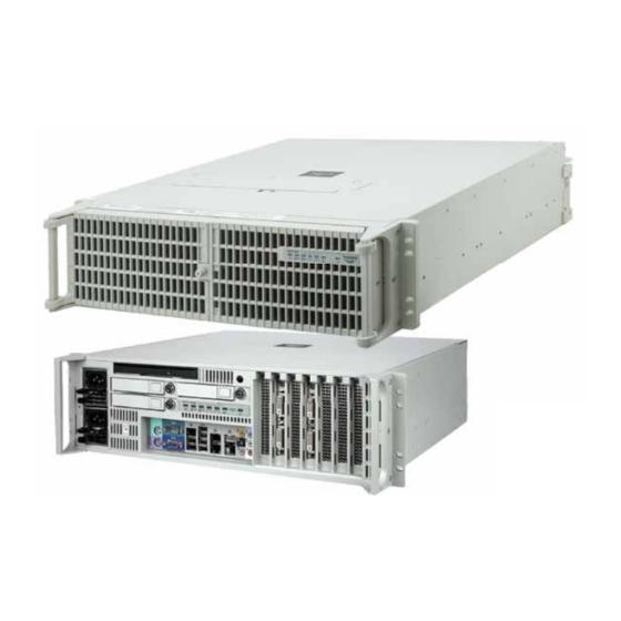
Themis RES-XR4-3U Installation Manual (184 pages)
3RU Rack-Mount Rugged Enterprise Server with Multiple Motherboard Configurations/Xeon CPUs
Brand:
Themis
| Category:
Server
| Size: 3.34 MB
Table of Contents
Safety Instructions
6
Grounding Methods
8
Sicherheitshinweise
11
Table of Contents
15
Table
25
Figure 1 Rugged Enterprise Server RES-XR4-3U
27
Preface
27
Figure 1-1 RES-XR4-3U
31
1 Overview and Specifications
31
Overview
31
Table 1-1 Major Features of the RES-XR4-3U
32
External Features
33
Table 1-2 RES-XR4-3U Motherboard Specifications
33
Figure 1-2 External Features of RES-XR4-3U (Rear I/O)
34
Figure 1-3 External Features of RES-XR4-3U (Front I/O)
35
System Leds and Indicators
35
Figure 1-4 RES-XR4-3U System Leds and Indicators
36
Table 1-3 System Leds
37
Figure 1-5 I/O Panel Diagrams
39
Table 1-5 I/O Connectors
40
Figure 1-6 RES-XR4-3U (Open Top View) (X9DRH Motherboard)
41
Figure 1-7 RES-XR4-3U (Open Top View) (X9DBL Motherboard)
42
Figure 1-9 X9DRH Block Diagram
44
Figure 1-10 X9DR3 Block Diagram
45
X9DR3 Block Diagram
45
Figure 1-11 X9DBL Block Diagram
46
X9DBL Block Diagram
46
C602/C606 Chipset
47
C606 Chipset
47
Chipset Overview
47
Environmental Temperature Control
49
Fan Status Monitor
49
PC Health Monitoring
49
Recovery from AC Power Loss
49
Special Features
49
Power Supply Monitoring
50
System Resource Alert
50
ACPI Features
51
Sample I2C Commands
51
Slow Blinking LED for Suspend-State Indicator
51
Overview of the Nuvoton WPCM450R Controller
52
Super I/O
52
WPCM450R DDR2 Memory Interface
52
WPCM450R PCI System Interface
52
Additional Supported Features of the WPCM450R
53
General Specifications for the RES-XR4-3U
54
Specifications
54
Table 1-6 RES-XR4-2U General Specifications
54
System Power
55
Table 1-7 RES-XR4-3U Electrical Specifications
55
Electrostatic Discharge
56
Environmental
56
Noise
56
Output Voltage
56
Shock
56
Figure 1-12 RES-XR4-3U with Noise Baffle Installed (Front View)
57
Figure 1-13 RES-XR4-3U with Rear Sound Baffle Installed (Rear View)
58
Figure 1-14 RES-XR4-3U with Rear Baffle Open
59
Accessory Kit
60
Packaging and Shipping
60
Approximate System Weights
61
Rack-Mount Slides (Optional)
61
Internal Views
41
Figure 1-8 RES-XR4-3U (Open Top View) (X9DR3 Motherboard)
43
Block Diagrams
44
X9DRH Block Diagram
44
Table 1-4 Power Supply LED Behavior
38
I/O Connectors
39
2 Installation and Operation
63
Installation Procedures
63
Remove Protective Top Cover
63
Figure
64
Figure 2-1 Remove the RES-XR4-3U Protective Access Cover
64
Memory Modules
65
Table 2-1 RES-XR4-3U System Memory Capacity
65
Table
65
Table 2-2 X9DRH and X9DR3 Slot/Cpu Assignment
66
X9DBL Slot/Cpu Assignment
66
Table
66
Table 2-5 X9DBL Processor and Memory Population
67
Table 2-4 X9DRH and X9DR3 Optimal Processor and Memory Population
67
Installation
68
Remove Air-Flow Deflector Screws
68
Figure
68
Figure
69
PCI Cards
72
RES-XR4-3U PCI-E 3.0 Slots
72
Figure 2-3 X9DRH/X9DR3 Memory Module Slot Locations
69
Table
72
Figure 2-8 X9DBL PCI Slots
73
Figure 2-7 X9DR3 PCI Slots
73
Figure 2-10 Lithium Backup Battery Location
75
Figure 2-12 Opening the RES-XR4-3U Front (Bezel) Doors
77
Storage-Drive Removal
78
Figure 2-14 RES-XR4-3U Storage Drive Removal
79
Removable 120-MM Fan
80
Storage Drive Installation
80
Removing and Installing an 120-MM Fan
81
Figure 2-18 Fan-Lid Locking Stud Capture
82
DC Power Supply Option
83
Power Supply
83
Installing a Lithium Battery
76
SAS/SATA Storage Drive
76
Opening the RES-XR4-3U Front Doors
77
Figure 2-19 DC Power Supplies
83
Figure 2-22 AC Power Socket and LED on the RES-XR4-3U Rear
87
Figure 2-23 System Power Button and LED on the RES-XR4-3U Front
87
Configuration
88
Getting Started
88
Linux Installation
88
Turning the System off
88
Figure 2-20 the RES-XR4-3U Power Supply Locking Mechanism
84
Removing a Power Supply
84
Installing a Power Supply
85
Rack Mounts
86
Mounting Brackets
86
Rack-Mount Slides (Optional)
86
Operation
87
Plugging in the AC Power Cords
87
Turning the System on
87
Installing Cards
74
Lithium Backup Battery
75
Locating the Lithium Backup Battery
75
Removing the Lithium Battery
75
3 BIOS Setup Utility
89
Introduction
89
Starting BIOS Setup Utility
89
How to Change the Configuration Data
90
Starting the Setup Utility
90
Figure 3-1 Main BIOS Setup Screen
91
Figure 3-2 Advanced Settings Screen
93
Figure 3-3 Event Logs Settings Screen
118
Erasing Settings
119
View Smbios Event Log
120
Figure 3-4 IPMI Settings Screen
121
Custom EFI Logging Options
122
Erasing Settings
122
Bootup Num-Lock
94
Interrupt 19 Capture
94
Re-Try Boot (X9DBL)
94
Wait for 'F1' if Error
94
CPU Power Management Configuration
97
Turbo Mode
98
Chipset Configuration
100
North Bridge
100
Qpi Link Frequency Select
103
Qpi Link Speed Mode
103
Channel Interleaving
104
DIMM Configuration
104
DIMM Information
104
Memory Mode
104
South Bridge
105
SATA Configuration
106
SATA Mode
107
Pcie/Pci/Pnp Configuration
108
PCI Latency Timer
108
PCI ROM Priority
108
Above 4G Decoding
109
ASPM Support
109
Maximum Payload
109
Maximum Read Request
109
PERR# Generation
109
SERR# Generation
109
CPU1 Slot 1 PCI-E 3.0 X8 OPROM, CPU1 Slot 2 PCI-E
110
Load Onboard LAN1 Option ROM, Load Onboard LAN2 Option ROM
110
Lsi Sas 2208 Oprom
110
Network Stack
110
Onboard LAN Option ROM Select
110
Oprom
110
PCI-E 3.0 X16 OPROM, CPU2 Slot 5 PCI-E 3.0 X8 OPROM, CPU2 Slot 6 PCI-E 3.0 X8 OPROM, CPU2 Slot 7 PCI-E 3.0 X8
110
SCU Configuration
108
Onchip SAS Oprom
108
SCU Port 0~3
108
Storage Controller Unit
108
Super IO Configuration
111
Serial Port 1 Configuration
111
Serial Port 2 Configuration
111
Serial Port Console Redirection
112
ACPI Settings
115
ACPI Sleep State
115
High Precision Timer
115
Trusted Computing
116
Current Status Information
116
Pending Operation
116
TPM State
116
TPM Support
116
Intel ME Subsystem Configuration
117
Intel TXT (LT-SX) Configuration
117
Intel TXT (LT-SX) Dependencies
117
Intel TXT (LT-SX) Hardware Support
117
Intel ® Trusted Execution Technology (TXT) (LT-SX)
117
ME (Management Engine) Subsystem
117
ME Subsystem
117
Change Smbios Event Log Settings
118
Enabling/Disabling Options
118
Event Logs
118
Enabling/Disabling Options
121
Ipmi
121
System Event Log (SEL)
121
BMC Network Configuration
122
Update IPMI LAN Configuration
122
Boot
124
Boot Option Priority
124
Administrator Password
125
Security Settings
125
User Password
125
Discard Changes and Exit
126
Save and Exit
126
Save Changes and Reset
126
BIOS Error Beep Codes
128
Main Setup
91
System Overview
92
System Time/System Date
92
Supermicro Motherboard Data
92
System Memory
92
Advanced Setup Configurations
93
BOOT Features
93
Addon ROM Display Mode
93
Quiet Boot
93
Power Configuration
94
Power Button Function
94
Watch Dog Timer
94
Restore on AC Power Loss
95
CPU Configurations
95
Socket 1/ Socket 2 CPU Information
95
Active Processor Cores
96
Clock Spread Spectrum
96
Limit Cpuid Maximum
96
Figure 3-5 Boot Settings
124
Figure 3-6 Security Settings
125
Figure 3-7 Exit Options
126
Table 3-1 BIOS Error Beep Codes
128
BIOS Recovery
129
Boot Sector Recovery from a USB Device
129
How to Recover the AMI BIOS Image (the Main BIOS Block)
129
Boot Sector Recovery from a Serial Port ("Serial Flash")
130
Boot Sector Recovery from an IDE CD-ROM
130
Save Options
127
Save Changes
127
Discard Changes
127
Restore Defaults
127
Save as User Defaults
127
Restore User Defaults
127
Boot Override
128
Figure 3-8 AMI_FLSH Hyperterminal
132
Figure 3-9 ROM File Extraction
132
Figure 3-10 FLASH Recovery
133
Appendix A. Connector Pinouts
135
PS/2 Keyboard and Mouse
135
PS/2 Keyboard/Mouse Pinout and Signal Descriptions
135
Table
135
USB Ports
136
Serial Port
136
COM1 Serial Connector Pinout
136
USB Connector Pinout Signal Descriptions
136
Table
136
COM1 Serial Connector Pinout Signal Descriptions
136
VGA Monitor Port
137
Figure A-3 VGA Connector Pinout
137
Table A-4 RES-XR4-3U VGA Connector-Pin Signals
137
Gigabit Ethernet LAN Ports
138
IPMI Dedicated LAN Port
138
RJ45 Ethernet Pinout Signals
138
Appendix B. Rack-Mount Slide Installation
139
Appendix C. Red hat Enterprise Linux 5 Installation
143
Introduction
143
Installation
143
Figure C-1 Power on after Linux DVD Is Inserted into Drive
144
Figure C-3 Welcome Screen
145
Figure C-4 Language Selection
146
Figure C-5 Selecting Layout Type
147
Figure C-6 Enter Installation Number
148
Figure C-7 Partitioning
149
Figure C-8 Reviewing Option
150
Figure C-9 Creating a Custom Layout
151
Figure C-10 Setting up Boot Loader
152
Figure C-11 Master Boot Record (MBR)
153
Figure C-12 Network Devices List
154
Figure C-13 Edit Interface Pop-Up Screen
155
Figure C-14 Selecting Time Zone
156
Figure C-15 Setting up Root Account and Password
157
Figure C-16 Package Installation Default Screen
158
Figure C-17 Optional Packages
159
Figure C-18 Option to Review or Continue
160
Figure C-20 Installation Is Complete
161
Figure C-21 Login Screen
162
Appendix D. Optional RES Audio/Usb/Serial Port Module
163
RES Audio/Usb/Serial Port Custom Module
163
Figure D-2 Install the RES Audio/Usb/Serial Port Custom Module
164
Attach I/O Cables
165
Figure
166
Table D-1 Dual USB Connector Pinout Signal Descriptions (J10
166
D.1.2.1 USB Ports a and B
166
Serial Port COM1
167
Stereo Audio Ports (Optional
168
Stereo Audio Connector Pinout
168
Figure
168
Ordering the RES Audio/Usb/Serial Port Custom Module
169
Appendix E. Repackaging Instructions
171
Repackaging for Shipment
171
Figure
172
Instructions for Repackaging
173
Packaging Components
172
Order of Assembly
173
Index
175
Reader Comment Card
184
Advertisement
Advertisement
Related Products
Themis RES-XR4-1U
Themis RES - 32XR3
Themis RES-12XR3-S
Themis RES-22DCX
Themis RES-11XR3
Themis RES-32XR3/FIO
Themis RES-32XR3-S
Themis RES-22XR3
Themis RES-12XR3
Themis RES-32XEL
Themis Categories
Server
Barcode Reader
Motherboard
Laboratory Equipment
Video Card
More Themis Manuals
Login
Sign In
OR
Sign in with Facebook
Sign in with Google
Upload manual
Upload from disk
Upload from URL