Table of Contents
Advertisement
Quick Links
Advertisement
Table of Contents

Related Manuals for UniPOS FS4000


Summary of Contents for UniPOS FS4000
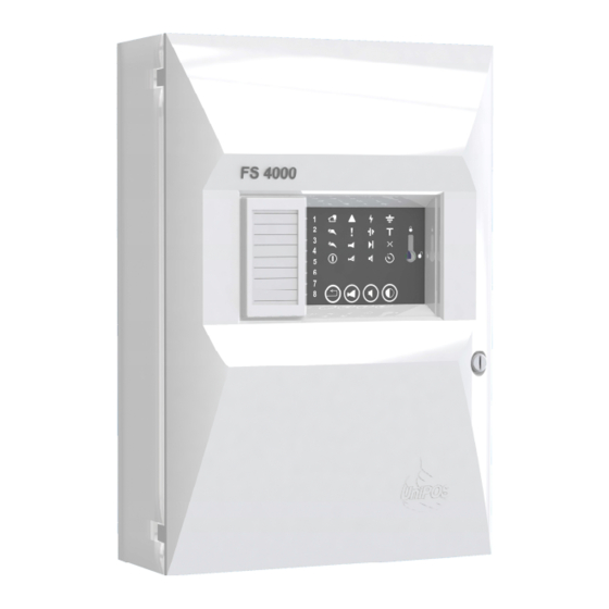
- Page 1 Fire Control Panel FS4000 INSTRUCTION MANUAL Revision 11/01.17...
-
Page 2: Table Of Contents
Contents Introduction ..........................Terminology ........................... Function ..........................Technical features ......................... 4.1 Fire alarm lines ........................4.2. Current thresholds for ......................4.3. Monitored output for fire condition ..................4.4. Relay output for fault condition ................... 4.5. Input for remote Reset fires……………………………………………………………………… 4.6. -
Page 3: Introduction
Fire Control Panel FS4000 1. Introduction Fire control panel FS4000 is an up-to-date, highly reliable, multifunctional and versatile unit. It is designed to receive signals from manual call points and automatic fire detectors, releasing sound and light indication. The fire control panel provides options for connection of external signal and executive units. -
Page 4: Function
FIRE CONDITION FIRST STAGE when authomatic detectors are activated at the same time in two lines. 3. Function Fire control panel FS4000 is designed to operate with conventional automatic fire detectors and manual call points. The panel has outputs provided for external executive devices. The unit is produced in four versions: ... -
Page 5: Relay Output For Fault Condition
Input for remote Reset fires operation or remote activation of the monitored outputs for Fire Alarm Devices (refer p.6.3); 8 pcs. UniPOS Automatic Fire Detectors (or 4 pcs. With connected RI31 remote indicators) simultaneously in Fire per zone, before the Short-circuit protection of the line is triggered. -
Page 6: Power Supply
- 304х222х94 mm 4.11. Dimensions 4.12. Weight, backup batteries not included - 0,98kg 5. Contents of delivery: Fire control panel FS4000 - 1 pc End of line resistors 3,0k / 0.6W for 2 lines - 2 pcs ... -
Page 7: General Information
General information 6.1. Access levels There are 4 levels of access to the variable indications and control functions of FS4000 6.1.1. Access level 1 All persons who would presumably find out and react to alarm for fault condition or fire condition have access to level 1. - Page 8 UniPOS Fire Control Panel FS4000 Conditions of the fire control panel Indication Indicator Delay of outputs - All conditions continuous yellow light Common indicator Fire condition – Fire condition flashing light or flashing red light Fire condition and Fault condition -...
-
Page 9: Duty Mode Configurations - General Information
UniPOS Fire Control Panel FS4000 Table 2 Condition of the fire Access Means of control Operation control panel level Button Reset Fire condition Level 2 Exit of Fire condition - if outputs for fire condition are activated – Button Outputs to suppress the outputs;... -
Page 10: Conditions Of The Fire Control Panel
13.3. Control over the monitored outputs of fault condition (short circuit or break) is being carried out as well. The fire control panel FS4000 operates in five basic modes: Duty Mode, Fire Condition, Fault Condition, Disabled Component Mode and Test Mode. -
Page 11: Using The Buttons
). The aim is to signal for forced evacuation if necessary. 7.4. Additional option In FS4000 there is opportunity for configuring line(s) in a definite way so that if signal for Fire condition, the Fire Control Panel enters directly in Fire condition 2 stage. -
Page 12: Using The Buttons
UniPOS Fire Control Panel FS4000 - if the outputs are suppressed by button , then the indicator is illuminated with red light; Local buzzer is activated. If the Control Panel is connected with local network by Remote Control Panel for indication, the... -
Page 13: Led And Sound Indication
UniPOS Fire Control Panel FS4000 Fault in power supply to external devices; - Network fault or fault in the transmitting device; In System fault the main processor is not able to continue operation. You can exit the System fault condition only if you disconnect the control panel from the mains supply and send it for repairs. -
Page 14: Disabled Component Mode
UniPOS Fire Control Panel FS4000 The button does not affect nor is its action cancelled by the following events: When new line enters Fire condition, the local buzzer will be activated; When new fault condition is registered, the local buzzer will be activated. -
Page 15: Disable/Enable Outputs In Fire Condition
UniPOS Fire Control Panel FS4000 With continuous yellow light are illuminated : - the Individual indicator of the line; - the indicator (if no other disabled components) 10.2.2. To cancel disabling a line Move the pair of switchers of the disabled line in position OFF OFF in accordance with table 3. -
Page 16: Switching On/Off Communicaton Interface Rs485
(if no other disabled components). 10.4. Switching ON/OFF communication interface RS485 The extension of FS4000 with module FD4201 allows the Fire Control Panel to participate in the local network composition and to communicate with other Fire control and Remote control panels DIP 7 (pos 3, fig .1) define On and Off communication interface RS485 as follows:... -
Page 17: Test Condition
UniPOS Fire Control Panel FS4000 11. Test condition 11.1. Description The Fire control panel enters Test Mode after a fire alarm line has been manually set to operate in test condition. Test Mode condition is set by a pair of DIP-switches ( pos.4, fig.1 ). Each line has a pair of switchers, whose position is determined by the operation mode ( fig.2 ) of each... -
Page 18: Delay Of Outputs
UniPOS Fire Control Panel FS4000 12. Delay of outputs 12.1. Description The Fire control Panel registers the time delayof the outputs after manual operation for setting the appropriate value.The time delay is set by a combination of 3 and 5 position of DIP-switch ( pos.3, Figure 1 and Table 4) and can be 0, 1, 2, 3, 4, 5, 6 or 7 minutes. -
Page 19: Installation And Initial Start Of The Fire Control Panel
UniPOS Fire Control Panel FS4000 position Switches On Switches On Switches On Switches On only in Fire only in Fire with time with time condition of lines condition of delay delay 1 or 2 lines 3 or 4 position Switches On... - Page 20 UniPOS Fire Control Panel FS4000 - Pull-out the interface board (fig.4) following the sequence: • push the holders on the top side (fig.4, pos.1); • take out (from the top holders) the interface board and leave it fixed on the bottom holders (fig.4, pos.
- Page 21 - The opening in the top left corner is only dedicated to the 220Vac mains power line (fig.5, pos.4), applicable for the FS4000 mains power supply; - The external opening, located on the topside of the cabinet are dedicated for surface mounting of the signal line (fig.6, pos.2) and mains power line (fig.6, pos.3);...
- Page 22 UniPOS Fire Control Panel FS4000 14.1.3.Preparation of the necessary cables in the cabinet of the FCP. - The length of the mains cable line (220 Vac), placed inside the cabinet must be 185 mm, as marked on the draft fig.7(A);...
- Page 23 UniPOS Fire Control Panel FS4000 14.1.4.Prepare and choice of place to installation FCP cabinet. - The distance between the wall and the backside of the FCP cabinet is 7 mm (fig. 8). For correct installation, there should be no cables or obstacles in the gap between the cabinet and the wall, which are more than 7 mm (fig.8, pos.1);...
- Page 24 UniPOS Fire Control Panel FS4000 Fig.9 - Take the signal and power lines through the dedicated openings (refer p.14.1.2) and mount the screws ( fig.9 pos.1) and fix cabinet on the wall. Instruction manual Page 24 Revision 11/01.17 of 34...
- Page 25 UniPOS Fire Control Panel FS4000 14.1.5. The signal lines and mains power line (220VAC) prepare to connect to main interface board. - The mains power line, passing through the dedicated opening (p.14.1.2) is fixed with tie-wraps in the cabinet on fig.10, pos.1.
- Page 26 UniPOS Fire Control Panel FS4000 14.1.6. The signal lines cable connection to main interface board. - For easy wires installation in the PCB connectors, the interface board is mounted to the bottom holders, as illustrated on fig.11, pos.1. - The signal cable lines, dedicated for the conventional zones and fire protection and fire alarm equipment, are fit to the PCB connectors in the main interface board (fig.11, pos.
- Page 27 UniPOS Fire Control Panel FS4000 14.1.7. Мains power line (220VAC) connection to the main interface board. The interface board is put back to its initial position (Fig.12) : - The bottom side of the interface board is mounted on the holders (fig.12, pos.1);...
- Page 28 UniPOS Fire Control Panel FS4000 14.1.8. Installation of the back-up batteries in FCP. - Install the back-up batteries in the cabinet of the FCP (fig.13, pos.1). The maximum capacity of the batteries is 7 Ah, but it is correct to install 1.2 Ah or 4.5 Ah back-up batteries, as well.
- Page 29 UniPOS Fire Control Panel FS4000 14.1.9. Close the cabinet. - Fit the front cover of the cabinet to its initial position (fig.14); - Install the screws in the dedicated openings of the front cover (fig.14, pos.1 and pos.2); - Put the plastic plugs to hide the screws (fig.14, pos.3);...
-
Page 30: Periphery Devices Assembly
UniPOS Fire Control Panel FS4000 14.2. Periphery devices assembly All connections are to be made by means of terminals, mounted on the printed circuit boards . Be advised, that the total consumption of the voltage powering the external devices (terminal “+ 24V”) shall not exceed 1,2 A in heavy duty mode. -
Page 31: Connecting Remote Reset Input / "Activate Monitored Outputs
UniPOS Fire Control Panel FS4000 14.2.3. Connection of extension module FD 4201 In Fire Control Panel FS 4000 there is a option for extension through module FD 4201. The module FD4201: - expand the panel’s outputs with additional 2, 4, 6 or 8 (depend from number of the lines in the panel) relay non-potential outputs, activated trough fire;... -
Page 32: Fire Control Panel Start Up
UniPOS wishes you a successful work! Instruction manual Page 32 Revision 11/01.17... -
Page 33: Appendixes
UniPOS Fire Control Panel FS4000 18. Appendixes Appendix 1 1. Area for LINE labeling 2. Individual LINE indicators for FIRE ( red ) and FAULT ( yellow ) condition 3. Confirmed fire condition from the Remote Control Panel ( red ) 4. - Page 34 UniPOS Fire Control Panel FS4000 Front panel of FS4000 Appendix 2 Instruction manual Page 34 Revision 11/01.17 of 34...
Need help?
Do you have a question about the FS4000 and is the answer not in the manual?
Questions and answers