Table of Contents
Advertisement
Advertisement
Table of Contents

Related Manuals for Laskomex CD-2502 Series

Summary of Contents for Laskomex CD-2502 Series
- Page 1 INSTALLATION, SERVICE AND PROGRAMMING MANUAL CD-2502xx DIGITAL ENTRY PHONE SYSTEM...
-
Page 2: Table Of Contents
CONTENTS CONTENTS Contents 1 Conditions of operation 2 Installation of entry phone 3 Elements of entry phone 4 Numbering modes 4.1 Normal mode ........4.2 Numbering mode with range shift . - Page 3 CONTENTS CONTENTS 10 Restoring the initial settings 11 Maintenance of entry phone 12 Conformity with previous versions 12.1 Electronic cassette ........12.2 External panel .
-
Page 4: Conditions Of Operation
1 CONDITIONS OF OPERATION NOTE! Entry phone CD-2502 is available in two versions: audio and video. In both versions the same electronic cassette EC-2502 and power supply adapters are used, in both versions parameters are set in the same way. The two versions differ mainly with the types of used panels, additional elements in video version (panels in video ver- sion, switches, distributors and monitors) and the method of performance of power system. -
Page 5: Installation Of Entry Phone
2 INSTALLATION OF ENTRY PHONE It is forbidden to hold the receiver near an ear and push the lever (hook- switch) in the uniphone/monitor base at the same time or hold the receiver near an ear while the lever (hook-switch) is pushed because this may cause a loud call signal in a receiver that can result in hearing defect. -
Page 6: Elements Of Entry Phone
3 ELEMENTS OF ENTRY PHONE In case the system of entrance hierarchy is activated, set the range limits for the apartments in cassettes operating as EC-2502/U (for subordinate entrances). Leaving default settings in these cassettes may cause wrong operation of the entry phone system. - Page 7 (during the call and conversation) 40 Ω and the line current in the active state I=(70-100mA). The use of uniphones not made by Laskomex may be associated with the invalid operation of entry phone system. Laskomex does not take the re-...
- Page 8 Monitor MVC–6550 and 6650 Colour monitors for Laskomex digital systems. They are loud speaking monitors without receivers with TFT display operating in duplex system. Detailed information on monitor assembly and use are included in the instruction enclosed to them.
-
Page 9: Power Supply
3 ELEMENTS OF ENTRY PHONE Power supply Ac power supply adapter ZS-K-25/01 art.0018 or TSZZM 25/021M should be used for supplying electronic cassette. Electro-catch or electromagnetic lock Entry phone CD-2502 can control electro-catch or electromagnetic lock. Op- eration time is programmed and can be changed by an installing specialist. It is recommended to use electro-catches for voltage 12V AC/DC and power consump- tion not exceeding 1A. -
Page 10: Numbering Modes
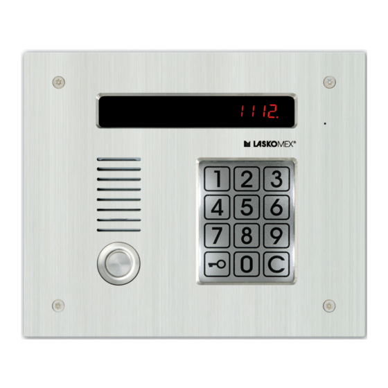
4 NUMBERING MODES Name of casing Destination - type of panel Description DA-1 one segment casing DA-2H two segment casing, horizontal DA-2V CP-2502xx two segment casing, vertical DA-3H three segment casing, horizontal DA-3V three segment casing, vertical DAX1-1 one segment casing DAX1-2H CP-2510 two segment casing, horizontal... -
Page 11: Hotel Numbering Mode
4.3 Hotel numbering mode 4 NUMBERING MODES the number from the keyboard). This numbering mode is used for apartments of numbers higher than 255. logical number = physical number + range shift This numbering mode is switched on in a moment of setting of parameter value ‘range shift‘... -
Page 12: Mode With Building Numbering
4.4 Mode with building numbering 4 NUMBERING MODES of entry phone programming procedures in the exchange can be used (P-3-5, P-3-6). numbers of rooms 1... 20 uniphone number 1, 2, ..20 ground floor numbers of rooms 101...120 uniphone number 21, 22,...41 I floor numbers of rooms 201...220 uniphone number 42, 42,...62 II floor... -
Page 13: Additional Numbers
4.6 Additional numbers 5 CONFIGURATIONS OF ENTRY PHONE OPERATION Additional numbers In many cases it is necessary to operate numbers which do not belong to the operated range. In entry phone CD-2502 these numbers can be associated with fourteen physical numbers: 241...254 (parameter Un in procedure P-1). For each of the mentioned numbers it is possible to set individually any number from the range 1...9998. - Page 14 5.2 System with entrance hierarchy 5 CONFIGURATIONS OF ENTRY PHONE OPERATION MVC-6x50 MVC-6x50 MV-6450 CVR-2 230V MV-6451 MVC-6x50 MV-6450 CVR-1 230V MVC-6x50 MV-6450 EC-2502/U EC-2502/U 230V 230V Figure 1: Basic system: a) audio version, b) video version with direct connection of monitors to bus-bar, c) video version with distributors.
-
Page 15: Installation And Activation
6 INSTALLATION AND ACTIVATION STAIRCASE B EC-2502/U CVR-2 EC-2502/H CP-25xx CVR-x Power supply to next distributor 230 VAC CVP-1 Signal branches STAIRCASE A CP-25xx EC-2502/U CVR-1 EC-2502/H CP-25xx Power supply to next distributor 230 VAC 230 VAC CVP-1 Power supply Figure 3: System with entrance hierarchy, version video. - Page 16 6.1 Performance of wiring system 6 INSTALLATION AND ACTIVATION In installations with the main entrance operation mode is set in electronic cassette. Depending on the selection they can function as cassettes servicing the main entrance (EC-2502/H) or subordinate entrance (EC-2502/U). Default setting of the cassette is configured to operate with the subordinate entrance.
- Page 17 6.1 Performance of wiring system 6 INSTALLATION AND ACTIVATION a uniphone and an electronic cassette should not exceed 150m for wire dia. 0.5 mm. This distance can be extended by increasing the cross-section of connecting wires. EC-2502/U 230 VAC Power supply Figure 4: Method of connecting uniphones to electronic cassette.
- Page 18 6.1 Performance of wiring system 6 INSTALLATION AND ACTIVATION It is forbidden to make wire branching (e.g. in junction boxes). Wire should be routed from one receiver (monitor, distributor, switch) to the next one. A rule should be obeyed that signal sent to the receiver by one wire and goes out by the other.
-
Page 19: Installation Of External Panel
6.2 Installation of external panel 6 INSTALLATION AND ACTIVATION branch 1 branch 2 EC-2502/U branch 3 branch 4 230 VAC Figure 6: Branching of video entry phone system by means of distributor CVR-x Installation of external panel Setting jumpers. Set correctly contact JP1 in symmetrizator plate (see dwg. 8). Value of selected resistance should correspond to wave impedance of used wire or cable. -
Page 20: Installation Of Electronic Cassette And Power Supply Adaptor
6.3 Installation of electronic cassette and Power supply adaptor 6 INSTALLATION AND ACTIVATION is not recommended. Figure 8: External panel – setting output impedance in a panel in video version. JP1 continuous supplying camera JP1 supplying camera while its illumination, according with EUc parameter JP2 3 segments display JP2 4 segments display... - Page 21 6.3 Installation of electronic cassette and Power supply adaptor 6 INSTALLATION AND ACTIVATION Loosen the mounting screws Remove the frame by lifting Remove plexi glass and move the frame towards it slightly and then moving plates the outside edge of a panel towards the outside edge of a panel Dents on the frame left side...
-
Page 22: Installation Of Modules Cvp-1 And Cvp-2
6.4 Installation of modules CVP–1 and CVP–2 6 INSTALLATION AND ACTIVATION Entry phone CD-2502 can control electro-catch or electromagnetic lock (or reverse electro-catch). Both elements are controlled in different ways. In case of electro- catch release of entrance interlock takes place after supplying voltage to electro- catch. -
Page 23: Installation Of Distributor Cvr-1 And Cvr-2
6.5 Installation of distributor CVR–1 and CVR–2 6 INSTALLATION AND ACTIVATION distributors, switches) to wire impedance. Load at C1 input should be set only in one of the switches - installed at the end of the line (by means of JP1 joint) in others all jumpers should be removed from the joint. - Page 24 6.5 Installation of distributor CVR–1 and CVR–2 6 INSTALLATION AND ACTIVATION It is not recommended to use with MV645x series monitors. It is recommended that wires sections connecting distributor with monitor connected to sockets MON1 and MON2 have comparable length. The same principle refers to wires connected to sockets MON3 and MON4.
-
Page 25: Installation Of Monitor
6.6 Installation of monitor. 6 INSTALLATION AND ACTIVATION Installation of monitor. Installation and connection of monitors should be made on the basis of instruction enclosed to models that were used. Installation and programming of uniphone We assume that for each apartment a uniphone connection wire is routed, this wire is connected to terminals L+, L- of the exchange and the line is not shorted. - Page 26 6.8 Activation 6 INSTALLATION AND ACTIVATION start installation procedure (P-3-0). exit programming mode (e.g. P-8). On display message U lub LOC will appear informing about installation proce- dure. Message U informs that installation procedure operates and occupants can use the entry phone. Message LOC informs that there is no possibility of entry phone use.
-
Page 27: Entry Phone Adjustment Cd-2502
MICROPHONE SPEAKER BALANCE Kaseta elektroniki EC-2502 ul. Nowa 20, 90-031 £ódŸ, tel. (0-42) 672 44 00, fax 672 44 45, DATA: e-mail: laskomex@laskomex.com.pl, http://www.laskomex.com.pl RESET MIKROFON BALANS G£OŒNIK CP-2500 Figure 17: Control elements a) control amplification of microphone in panel, b) control elements... -
Page 28: Programming Of Entry Phone
8 PROGRAMMING OF ENTRY PHONE Balance control If during a conversation or replacing the receiver there are acoustic disturbances (whistles, squeaks etc.) line balance should be adjusted. For this purpose we call a uniphone installed more or less in the middle of the line length L+, L-. By potentiometers P2 and P1 we set preliminarily the volume of conversation in both directions. -
Page 29: Operation Parameters Of Entry Phone
8 PROGRAMMING OF ENTRY PHONE presented on the following drawing. VALUE PREVIEW EDITION / APPROVAL CANCEL Figure 19: Function keys in programming mode Function key KEY is used for switching to parameter edition mode and accepting entered values. Using key KEY it is possible to return to main menu level (on the display message P- . -
Page 30: P-1 Operation Parameters Of Entry Phone
8 PROGRAMMING OF ENTRY PHONE P-1 Operation parameters of entry phone EDITION - PARAM. PARAM. EDITION - CHANGE NEW VALUE No 1 No 2 ACCEPTATION OLD VALUE RETURN In first column with bold font is a message that is shown on panel‘s display during edition of parameter. In third column are acceptable values of parameter. - Page 31 8 PROGRAMMING OF ENTRY PHONE Video signal service CAin Supported video in- 0...1234 Inputs of CVP-x switch which are serviced by CD system. Value puts ’0’ of parameter means using a CVP-1 switch, while a value greater than zero means CVP-2 switch - the individual digits in the number means which inputs in the switch are used (eg.
-
Page 32: Functions Realized By Entry Phone
8 PROGRAMMING OF ENTRY PHONE P-2 Functions realized by entry phone Parameters P2 can have values [-0-] or [-1-]. In third column default value of parameter is given. Value [-1-] means switched on function, value [-0-] – switched off function. In fourth column type of electronic cassette (U or H) is shown where parameter‘s edition is possible. - Page 33 8 PROGRAMMING OF ENTRY PHONE Switching on three- Function should be switched on when electronic cassette EC-2502 coop- position display erates with the panel with three position of old type. In such case some messages appearing on the display will be distorted. Switching on the three position service makes that some messages appearing on the display will differ from those described in the instruction.
-
Page 34: P-3Installation Procedure
8 PROGRAMMING OF ENTRY PHONE P-3 Installation procedure The procedure facilitates the activation of an entry phone system. Starting procedure P3 enables the installing specialist to check the correctness of functioning of uniphones mounted in apartments without any help of other persons. -
Page 35: Electronic Keys
8 PROGRAMMING OF ENTRY PHONE P-4 Electronic keys Entry phone CD-2502 can be equipped with iButton and/or RFID electronic key reader. There are three kinds of keys in entry phone. Service keys enable change of entry phone configuration, special keys are used by postmen, administration etc. - Page 36 8 PROGRAMMING OF ENTRY PHONE APARTMENT POSITION END OF OPERATION NUMBER IN MEMORY P-4-2 Addition of key with attributing Procedure enables adding of key and attributing it to selected apart- to apartment ment number, which facilitates keys management. The use of the key is signalled in uniphone receiver as in the case of combination lock.
- Page 37 8 PROGRAMMING OF ENTRY PHONE APARTMENT NUMBER P-4-4 Key deleting Deleting the key from memory will take place after applying it to the reader. On the display a message CAS will appear and a number which defines the memory item in which the deleted key was recorded. NOTE: To delete special key or administrator‘s key use procedure P-4-6.
- Page 38 8 PROGRAMMING OF ENTRY PHONE P-4-9 Programming of service key (ad- Service key functions similarly to administrator‘s code it enables to enter ministrator) programming procedures and service key functions independently of ad- ministrator‘s code. This operation results in replacing the old key with a new one.
-
Page 39: Individual Settings
8 PROGRAMMING OF ENTRY PHONE P-5 Individual settings In system CD-2502 there is a possibility of individual settings of some parameters of entry phone connected with uniphone calling and functions of combination lock. Values of parameters 1-3 may be changed by occupants by user‘s menu (see page. - Page 40 8 PROGRAMMING OF ENTRY PHONE Parameter No. 5. Entrance service, key 5 In the entry phone it is possible to define how the pushbutton operates the electro-catch at the individual entrances. – — No electro-catch control from the uniphone (monitor). U —...
-
Page 41: Change Of Installing Specialist's Code
9 ENTRY PHONE USE P-6 Change of installing specialist‘s code The code of an installing specialists enables entering the entry phone programming code. In case of installing specialists or property administrators it is convenient to use one common code for all entry phones which should be maintained. -
Page 42: Connection From The Main Entrance
9.2 Connection from the main entrance 9 ENTRY PHONE USE receiver. If the receiver in the apartment is picked up, this symbol changes to ouo and a conversation can be conducted. If the receiver in the apartment is not picked up then after several seconds the entry phone will return to normal operation mode. -
Page 43: Use Of Uniphone
9.3 Use of uniphone 9 ENTRY PHONE USE be signaled with message CALL Entry phone CD-2502 realizes functions ”fast en- trance” which is used only in entry phone with the main and subordinate entrances. In entry phone without this function one must ring the occupant twice in order to get to his apartment (the first time at the main entrance and the second time at the entrance to the staircase). -
Page 44: Using Coded Lock Function
9.5 Using coded lock function 9 ENTRY PHONE USE Using coded lock function To each apartment one four digit number is attributed which is preliminary defined in the entry phone production process. This code can be changed by an installing specialist or occupant (unless this option is blocked). - Page 45 9.7 User‘s menu 9 ENTRY PHONE USE register new electronic keys. To make changes an occupant must activate user’s menu. Some person in the apartment must help. User‘s menu activation: a) Make connection with the apartment (only from the subordinate entrance panel).
-
Page 46: Restoring The Initial Settings
10 RESTORING THE INITIAL SETTINGS Registering of a new electronic key In user’s menu after selecting 8, message [ADD] will appear on the display. Elec- tronic key should be put to the reader. Message [NEU] means that key was recorded in memory and attributed to the apartment. -
Page 47: Maintenance Of Entry Phone
P-3-9 Restoring the default values of individual settings for apartments. RESET Kaseta elektroniki EC-2502 ul. Nowa 20, 90-031 £ódŸ, tel. (0-42) 672 44 00, fax 672 44 45, DATA: e-mail: laskomex@laskomex.com.pl, http://www.laskomex.com.pl INIT RESET MIKROFON BALANS G£OŒNIK CP-2500... -
Page 48: Conformity With Previous Versions
Using these panels requires modification of electronic cassette. Detailed information on this subject is available in Laskomex service. NOTE! Correct work of RFID function in CP-25xxR panel ensure cooperation only with EC-2502R electronic cassette. -
Page 49: Messages About Faults
14 TECHNICAL DATA system built on the basis CD-2501 or CD-2502, where to one of the staircases the service of the next staircase should be added entry phone CD-2501/U or CD-2502 can be replaced with entry phone CD-3100. Messages about faults The doorphone CD-2502 can signal the following faults: EC: Means that two or more infrared beams are damaged or covered E2: Means short-circuit of uniphone line. -
Page 50: Description Of Terminals
14.1 Description of terminals 14 TECHNICAL DATA Ambient temperature (-25 +55) Degree of protection Electronic cassette EC-2502: IP20 External panel CP-xxx: IP44 Uniphone (each model for CD-2502): IP30 Monitor (each model for CD-2502): IP30 CVR-1, CVR-2, CVP-1, CVP-2, MRL-1: IP30 14.1 Description of terminals Electronic cassette... - Page 51 14.1 Description of terminals 14 TECHNICAL DATA External panel el. supply of the cassette digital part digital data from/to cassette digital mass (display system) loudspeaker of talking cassette analogue mass microphone of talking cassette C1+ video signal output video signal output electronic key reader electronic key reader –...
-
Page 52: Dimensions Of Elements
15 DIMENSIONS OF ELEMENTS Dimensions of elements Figure 22: Dimensions of electronic cassette EC-2502 Figure 23: Dimensions of distributor CVR-1, CVR-2 and switch CVP-1 and CVP-2... - Page 53 15 DIMENSIONS OF ELEMENTS Figure 24: Dimensions of panels CP-2502xx with a frame for mounting under plaster 13 otw. O 5.5 9 otw. O 5.5 DA-2V DA-3V Figure 25: Dimensions of casings mounted on plaster in vertical arrangement, for CP-2502xx...
- Page 54 15 DIMENSIONS OF ELEMENTS DA-1 5 otw. O 5.5 DA-2H 10 otw. O 5.5 DA-3H 10 otw. O 5.5 Figure 26: Dimensions of casings mounted on plaster in horizontal arrangement, for CP-2502xx CP-2510 NP2512 NP2511 Figure 27: Dimensions of panels CP-2510 and panels NP2512, NP2511...
- Page 55 15 DIMENSIONS OF ELEMENTS DAX1-2V Figure 28: Dimensions of casings mounted on plaster in vertical arrangement, for CP-2510 DAX1-1 DAX1-2H Figure 29: Dimensions of casings mounted on plaster in horizontal arrangement, for CP-2510...
- Page 56 15 DIMENSIONS OF ELEMENTS CP-2520 NP2522 NP2521 Figure 30: Dimensions of panels CP-2520 and panels NP2522, NP2521 DAX2-2V Figure 31: Dimensions of casings mounted on plaster in vertical arrangement, for CP-2520...
- Page 57 15 DIMENSIONS OF ELEMENTS DAX2-1 DAX2-2H Figure 32: Dimensions of casings mounted on plaster in horizontal arrangement, for CP-2520 Figure 33: The way of connection CP panel with NP list of occupants using fixing elements a) CP-251x and CP-252x panels, b) CP-2530 panel...
- Page 58 15 DIMENSIONS OF ELEMENTS CP-2530 NP2531 Figure 34: a) Dimensions of panels CP-2530 and NP2531; b) Dimensions of casings mounted on plaster in vertical arrangement, for CP-2530...
-
Page 59: Selection Of Wires And Connection Diagrams
16 SELECTION OF WIRES AND CONNECTION DIAGRAMS Selection of wires and connection diagrams the furthest uniphone 2 (B1,B2) Doorbell button LG-8d Distance feeder-LG-8d 15V DC/1A Clamps <50m <100m VS,GS 0,5mm 2x0,5mm YTKSY,UTP,LAN T11, XzTKMXpw LG-8d Distance Clamps <15m GS,VS uniphone Distance U-E Clamps <50m... - Page 60 16 SELECTION OF WIRES AND CONNECTION DIAGRAMS the furthest monitor Distance CVR-M Clamps <30m L+,L-,C+,C- 0,5mm VC,GV/GC 0,5mm YTKSY,UTP MON1 CVR-1 MV-645x 15V DC MON4 MON3 CVR-2 Distance CVR-M Clamps <15m <30m L+,L-,C+,C- 0,5mm Distance +15V,GND 0,5mm 2x0,5mm Clamps <15m YTKSY,UTP +15V, GND MON2...
- Page 61 16 SELECTION OF WIRES AND CONNECTION DIAGRAMS Uniphone Uniphone Uniphone NOTE! On the diagram the sequence of terminals was changed 12 V AC 14,5 V AC 0,8 A NOTE! power supply Terminals GZ, GZA and VZ, VZA of electronic are connected permanently 230 V AC cassette inside electronic cassette.
- Page 62 16 SELECTION OF WIRES AND CONNECTION DIAGRAMS Uniphone Uniphone 12 V AC 14,5 V AC 0,8 A power supply of electronic cassette 230 V AC EC-2502/U CP-25xx Electro-catch 12 V AC 14,5 V AC 0,8 A NOTE! Terminals GZ, GZA and VZ, VZA power supply are connected permanently of electronic...
- Page 63 16 SELECTION OF WIRES AND CONNECTION DIAGRAMS stabilizer +12V 1,85 A electro-catch lock demagnetising Figure 39: Electronic cassette block diagram brown Distributor CVR-1 PLUG RJ 45 brown - white NOTE! in every monitor connected to distributor green CVR-1 jumper Z1 should be in position blue - white UTP+TERM! blue...
- Page 64 16 SELECTION OF WIRES AND CONNECTION DIAGRAMS Local power supply 13,5V DC/1A MVC-6x50 230V AC/50Hz ..+15V L- 1C+ +15V CVR-2 MON1 MON4 Power supply 13,5V DC/1A 230V AC/50Hz Electronic cassette EC2502 Figure 42: System CD-2502 video. Connection of monitors using CVR-2 distributor - local power supply of monitors MON1 MON2...
- Page 65 16 SELECTION OF WIRES AND CONNECTION DIAGRAMS to another distributor or change-over switch MON1 MON2 MON3 MON4 CVR-x 14,5 V AC 12 V AC 0,8 A power supply of electronic cassette 230 V AC EC-2502/U CP-25xxV Electro-catch CVP-1 12 V AC 14,5 V AC 0,8 A power supply...
- Page 66 16 SELECTION OF WIRES AND CONNECTION DIAGRAMS MON1 MON2 MON3 MON4 CVR-x NOTE! In distributor CVR-x used for branching signal, set load (jumper JP1) to value equal to wire impedance. MON1 MON2 MON3 MON4 CVR-x MON 3 MON 4 CVR-2 12 V AC 14,5 V AC 0,8 A...
- Page 67 P–1 Operation parameters of entry phone EtyP Operation mode of electronic cassette 10...255 Waiting time for picking up the receiver in seconds 10...255 Time of conversation 10...255 Time of signal generation 20...255 Pause time 1...31 Time of electro-catch operation in seconds 0...200 Frequency of electro-catch supply voltage in Hz CAin...
- Page 68 List of collecting units of used Laskomex equipment is available on www.laskomex.com.pl website or telephone No. 42 671 88 68. Product packing should be removed according to environment protection regulations.
Need help?
Do you have a question about the CD-2502 Series and is the answer not in the manual?
Questions and answers