Table of Contents
Advertisement
Quick Links
Instructions/Parts
Stainless Steel,
Steel, Air
Stainless
Stainless
Steel,
with
with
with Pressure
Pressure Tank
Pressure
Radial piston
piston air
air driven
driven agitators
Radial
Radial
piston
air
driven
coatings.
coatings. For
coatings.
For professional
For
professional use
professional
Important
Important Safety
Important
Safety
Safety Instructions
Read all warnings and instructions in this manual before using the
Save these
equipment. Save
Save
Pressure Tank— 100 psig (0.7 MPa, 7
bar) Maximum Working Pressure
Agitator— 70 psig (0.5 MPa, 5 bar)
Maximum Recommended Operating
Pressure
See page 2 for model part numbers and
approvals information.
Air - - - Driven
Driven Agitators
Air
Driven
Tank
Tank
agitators for
for maintaining
maintaining suspension
agitators
for
maintaining
use only.
use
only.
only.
Instructions
Instructions
these instructions.
instructions.
these
instructions.
PROVEN QUALITY. LEADING TECHNOLOGY.
Agitators
Agitators
suspension and
and even
even- - - mixing
suspension
and
even
3A4797F
mixing in in in industrial
industrial paints
paints and
mixing
industrial
paints
EN
and
and
Advertisement
Table of Contents

Related Manuals for Graco 25C539


Summary of Contents for Graco 25C539
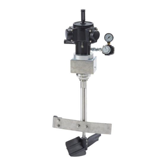
- Page 1 Instructions/Parts Stainless Steel, Steel, Air Air - - - Driven Driven Agitators Agitators Stainless Stainless Steel, Driven Agitators with with with Pressure Pressure Tank Pressure Tank Tank 3A4797F Radial piston piston air air driven driven agitators agitators for for maintaining maintaining suspension suspension and and even...
-
Page 2: Table Of Contents
Contents Contents Contents Related Manuals ..........2 Parts..............19 All Models ........... 19 Models............... 3 Tank Parts for Models 25C536, 25C537, Warnings ............4 25C538.......... 21 Installation............6 Accessories............23 Typical System ..........6 Strainer 240418 ........... 23 Air Regulator and Mufflers ......7 Buna-N Air Supply Hose....... -
Page 3: Models
Tank Part Part No. Part Description Description Description Approvals Approvals Approvals 25C539 Agitator (to be used with a 5 gallon tank) II II II 1/2 1/2 G G G 25C540 Agitator Ex h h h IIB IIB T4 T4 Ga/Gb... -
Page 4: Warnings
Warnings Warnings Warnings Warnings The following warnings are for the setup, use, grounding, maintenance, and repair of this equipment. The exclamation point symbol alerts you to a general warning and the hazard symbols refer to procedure-specific risks. When these symbols appear in the body of this manual, refer back to these Warnings. Product-specific hazard symbols and warnings not covered in this section may appear throughout the body of this manual where applicable. - Page 5 Warnings WARNING WARNING WARNING EQUIPMENT EQUIPMENT EQUIPMENT MISUSE MISUSE MISUSE HAZARD HAZARD HAZARD Misuse can cause death or serious injury. • Do not operate the unit when fatigued or under the influence of drugs or alcohol. • Do not exceed the maximum working pressure or temperature rating of the lowest rated system component.
-
Page 6: Installation
Installation Installation Installation Installation Typical System System Typical Typical System Be sure that all accessories are properly rated to withstand the pressures in the system. Note Throughout the manual, reference numbers and letters in parentheses refer to numbers and letters in figures and the parts drawings. -
Page 7: Air Regulator And Mufflers
(not provided) to space the regulator connector, and swivel connector are not factory farther away from the motor. installed on models 25C539, 25C540, and 25C541. Follow the directions below to install these items: Note 1. Screw the swivel connector (F) (see below) into Use of the third muffler is not necessary, the desired port (upper or lower) in the motor (K). - Page 8 Installation Clockwise Agitator Agitator Rotation Rotation Counterclockwise Agitator Agitator Rotation Rotation Clockwise Clockwise Agitator Rotation Counterclockwise Counterclockwise Agitator Rotation Reference Reference Reference Letter Letter Letter Description Description Description Mufflers Plugs Swivel connector Nipple connector Air regulator Air gauge Air motor 3A4797F...
-
Page 9: Agitator
• If installing a new agitator onto a new tank, follow steps 1– 2, and 7–15 (models 25C536, 25C537, 25C538). • If replacing an established agitator, follow steps 1, 3–12, and 14–15 (models 25C539, 25C540, 25C541). • If replacing the agitator drive with kit 19A844, follow the steps described in Installing Motor Conversion Kits, page 1. - Page 10 Installation 12. Assemble the paddle (45) on the shaft (47). See 14. Remove the plug or existing elbow from the air the figure below. Align the bottom of the paddle inlet manifold (5). Install the new elbow (69) into hub flush with the bottom of the shaft. Tighten the the pressure tank air inlet manifold.
-
Page 11: Grounding
Installation Grounding Grounding Grounding • To ground the pressure tank, connect one end of a 12 awg (1.5 mm ) minimum ground wire to the pressure tank and the other end of the wire to a true earth ground. Connecting Hoses Hoses Connecting Connecting... -
Page 12: Operation
Operation Operation Operation Operation 3. Be sure the ground wire is attached. 4. Replace the filler cap or cover, tighten the c-clamp handles to 8-10 ft-lbs, approximately 1/2 to 1 turn past hand tight. Personal injury, such as splashing in the eyes, may result from pressure in the tank. -
Page 13: Pressure Relief Procedure
Operation Pressure Relief Relief Procedure Procedure Safety Relief Relief Valve Valve Pressure Pressure Relief Procedure Safety Safety Relief Valve A safety relief valve (4) automatically relieves the Follow the Pressure Relief Procedure tank pressure when the air pressure exceeds 95 to whenever you see this symbol. -
Page 14: Maintenance
Maintenance Maintenance Maintenance Maintenance Air Motor Motor Muffler Motor Muffler Muffler Depending on the environment of the motor, periodically check the cleanliness of the air motor muffler. Dirty or clogged air mufflers result in Moving parts, such as an impeller blade, can cut decreased motor efficiency and may cause the motor or amputate fingers. -
Page 15: Cleaning The Tank
Maintenance Cleaning the the Tank Tank Cleaning Cleaning Tank 3. Remove the tank cover. 4. Empty the fluid from the tank and pour a suitable amount of solvent into it Note Be sure that the solvent is compatible with the fluid being sprayed and with the wetted materials in the tank. -
Page 16: Service
Graco distributor for repair or replacement. 4. Install the motor (34) and adapter plate (22) assembly on the top of the bracket (58) using Motor rebuild kits are available and listed in the table the four screws (26). -
Page 17: Couplings
Service Servicing the the Agitator Agitator Shaft Shaft and Servicing Servicing Agitator Shaft Couplings Couplings Couplings Setting Setting Setting the the Agitator Agitator Agitator Shaft Shaft Shaft Coupling Coupling Coupling 1. With the agitator shaft (47) pushed up against the lower washer (48), secure the lower portion of the coupling half (52c) to the shaft by tightening the coupling set screw against the flat on the shaft. -
Page 18: Installing Motor Conversion Kits
Service Installing Motor Motor Conversion Conversion Kits Kits Installing Installing Motor Conversion Kits Replacing Replacing Replacing the the Agitator Agitator Agitator Shaft Shaft Shaft 1. Remove the agitator paddle (45). Remove the Installing Installing Motor Installing Motor Motor Conversion Conversion Conversion Kit Kit 19A844 19A844... -
Page 19: Parts
Parts Parts Parts Parts All Models Models Models Locate the bottom shoulder of the shaft (47) against the bottom washer (48) when assembling the coupler (52c). Bearings 66 and 67 are not used on the 5-gallon model. Attach the U-bolt (56) to the support shaft (44). -
Page 20: 25C538
Safety Tag (not shown) Shaft, Agitator; 15 inches; 188886 Models 25C536 and ▲ Replacement safety labels, signs, tags, and 25C539 cards are available at no cost. Shaft, Agitator; 21 inches; * A welded 304 stainless steel paddle is available. 188887 Models 25C537 and Order part number 186517. - Page 21 Parts Tank Parts Parts for for Models Models 25C536, 25C536, 25C537, 25C537, 25C538 25C538 Tank Tank Parts Models 25C536, 25C537, 25C538 3A4797F...
- Page 22 Parts Part Part No. Part No. Description Description Description Part Part Part No. No. Description Description Description 100361 Plug, Pipe 210575 Cap, Filler 100840 Fitting, Elbow, Street Fitting, Nipple, Pipe 159239 Reducing 164724 Hose, Coupled ▲ 175078 Label, Warning 103347 Valve, Safety;...
-
Page 23: Accessories
Accessories Accessories Accessories Accessories Strainer Strainer Strainer 240418 240418 240418 Nylon Nylon Fluid Nylon Fluid Supply Fluid Supply Hose Supply Hose Hose 300 psi (2.1 MPa, 21 bar) Maximum Working 300 psi (2.1 MPa, 21 bar) Maximum Working Pressure Pressure Install at the tank air inlet to remove dirt and moisture 3/8”... -
Page 24: Dimensions
Dimensions Dimensions Dimensions Dimensions Reference Dimension Dimension Dimension Reference Dimension Dimension Dimension Reference Reference Reference Reference 5 gallons: 13.2 in. (335 mm) 19 in. (483 mm) 10 gallons: 18.2 in. (462 mm) 15 gallons: 28.9 in. (735 mm) 14 in. (356 mm) 5 gallons: 30.5 in. - Page 25 Dimensions Reference Dimension Reference Dimension Reference Reference Dimension Dimension Reference Reference Dimension Dimension 25C539: 25.5 in. (648 mm) 11.7 in. 25C540 31.3 in. (794 mm) (297 mm) 25C541 41.5 in. (1054 mm) 3A4797F...
-
Page 26: Air Consumption
Air Consumption Air Consumption Consumption Consumption 34.0 25.5 Standard 17.0 SCFM Cubic Meters/Hr 1000 1200 Air Motor RPM A — 20 psi (1.4 bar, 0.14 MPa) B — 40 psi (2.8 bar, 0.28 MPa) C — 60 psi (4.1 bar, 0.41 MPa) D —... -
Page 27: Technical Specifications
Weight 25C536 66 lbs (30 kg) 25C537 77 lbs (35 kg) 25C538 93 lbs (42 kg) 25C539 13 lbs (5.9 kg) 25C540 14 lbs (6.4 kg) 25C541 15 lbs (6.8 kg) Maximum working pressure, high 100 psig (0.7 MPa, 7 bar) - Page 28 Graco to be defective. This warranty applies only when the equipment is installed, operated and maintained in accordance with Graco’s written recommendations. This warranty does not cover, and Graco shall not be liable for general wear and tear, or any malfunction, damage or wear caused by faulty installation, misapplication, abrasion, corrosion, inadequate or improper maintenance, negligence, accident, tampering, or substitution of non-Graco component parts.
Need help?
Do you have a question about the 25C539 and is the answer not in the manual?
Questions and answers