Table of Contents
Advertisement
Quick Links
Advertisement
Table of Contents

Subscribe to Our Youtube Channel
Summary of Contents for Accusonic 8510+ series
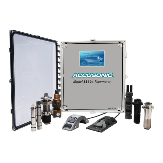
- Page 1 8510+ Series Flowmeter Technical Reference Manual 8510MA099 A2 Accusonic, a Brand of ADS LLC. 259 Samual Barnet Blvd New Bedford, MA 02745 508-273-9600 www.accusonic.com Copyright 2016 Accusonic All Rights Reserved Brand of ADS LLC An IDEX Fluid and Metering Business...
- Page 2 Accusonic 8510+ Series Flowmeter Technical Reference Manual 8510MA0099 REV A2 259 Samual Barnet Blvd. New Bedford, MA 02745 +1-508-273-9600...
- Page 3 Accusonic 8510+ Series Flowmeter 2016 ADS LLC. All rights reserved. , ADS Environmental Services , and Accusonic are registered trademarks of ADS LLC. Notice of Proprietary Information The information contained herein represents the latest information available at the time of publication. ADS LLC reserves the right to make any changes or modifications to the content of this document, without notice, to reflect the latest changes to the equipment.
- Page 4 Table of Contents INTERFACES SUPPLIED (UNLESS NOTED AS OPTIONAL) Power Supply Voltage 90 to 250 V a.c. 47 to 63 Hz, or 100 to 300 V d.c. Signal Filters Transducer Frequency 1 MHz / 500 kHz and 200 kHz Analog Inputs Number 4 (2-Path &...
-
Page 5: Table Of Contents
Accusonic 8510+ Series Flowmeter Table of Contents C H A P T E R 1 Flowmeter Description C H A P T E R 2 General Specifications Transducers ............. 2-1 Electronic Unit ............2-1 Transducer Cable ............ 2-2 Conformity with EMC and Safety Standards ..2-3 FCC Compliance ............ - Page 6 Table of Contents Connecting a PC ............. 4-9 Connecting a ModBus Master Device ....4-10 C H A P T E R 5 Initial Setup and General Operations Touch Screen LCD Display, Parameters and Variables ..............5-1 Menus ..............5-1 Stepping Through the Parameters Menus ....
- Page 7 Accusonic 8510+ Series Flowmeter Coil/Status Signals ..........C-5 Read-Write Registers ..........C-7 Index In-1...
-
Page 8: Chapter 1 Flowmeter Description
C H A P T E R 1 Flowmeter Description The Accusonic Model 8510+ Flowmeter is designed for use in pipes, channels and sewers, ranging from 8 inches to 300 feet (0.2m to 90m) in width, and of cross section which may be circular, rectangular, trapezoidal, “horseshoe”... - Page 9 Accusonic Model 8510+ Series Flowmeter When the Level is too low for any acoustic paths to operate (or if they are submerged and have failed), flow may be computed using the Manning equation. When the level is higher and ultrasonic paths are operating, a “Trapezoidal”...
-
Page 10: Chapter 2 General Specifications
Power Consumption Standard Unit: 10 Watts, 20 VA.(with AC power supply) With relays: 25 Watts, 40 VA. (with AC power supply) Contact Accusonic for details of models suitable for 24 Volts DC power supply. Temperature Range Operating: -4F to 160F (–20C to 70C) Storage: 0F to 160F (–18C to 70C) -
Page 11: Transducer Cable
Accusonic Model 8510+ Series Flowmeter Weight 30 lb (14 kg) Enclosure protection NEMA 4X (IP66) Up to 10 total, allocated between all the Sections. Acoustic Paths Length Standard range 0.7 to 50 ft. (0.2 to 15 m) Length Extended ranges 5 to 300 ft. -
Page 12: Conformity With Emc And Safety Standards
Note: Approval from Accusonic should be obtained if the cables are expected to exceed 300 ft (100m). Conformity with EMC and Safety Standards The Model 8510+ Flowmeter is designed and constructed in conformity with the following standards or normative documents, and with the essential requirements of the European Low Voltage Directive 73/23/EEC and the EMC Directive 89/336/EEC with amend. -
Page 13: Fcc Compliance
Accusonic Model 8510+ Series Flowmeter FCC Compliance To comply with the Federal Communications Commission (FCC), Accusonic Technologies provides the following information concerning the 8510+ flowmeter installation and operation. Part 68 This equipment complies with Part 68 of the FCC Rules and the requirements adopted by the ACTA. It bears a label displaying, among other information, a product identifier in the format US:AAAEQ##TXXXX. -
Page 14: Interface Specifications
General Specifications Interface Specifications Analog Level Input Level is input in 4-20 mA analog form, from an external current loop source. Both terminals at the flowmeter must be within 20 volts of ground for operation. The external device should be configured to give increasing current for increasing water depth. -
Page 15: Relay Outputs
Accusonic Model 8510+ Series Flowmeter section, variable to be output, range, and output under fault condition, are all defined under Analog Output parameters (for definitions see Chapter 7). Under fault conditions, the outputs will go either to 4.00 mA or be held at the last good value, depending on the choice under the parameter Hold on Error. -
Page 16: Data Display On Touch Screen Lcd Display
General Specifications In the event of power failure or the flowmeter being taken out of the Measure mode for less than one hour, the relay may operate at a rate of once per measurement cycle until the number of relay pulses has caught up with the Volume change which was computed to have occurred during the outage. -
Page 17: Connection Of A Pc For Use With Accuflow Flowmeter Interface
A PC may be connected to the 9-pin RS-232 socket or the RJ45 Ethernet socket, for use with special Accusonic PC based programs. The RS-232 connection requires a Null-Modem connection and the Ethernet connection requires a Cross-Over LAN cable or a standard LAN cable if connection via a switch or router. -
Page 18: Chapter 3 Flow Computation
Flow Computation Flow Computation Algorithms Overview The Accusonic Model 8510+ Flowmeter may be configured with up to a maximum of ten acoustic paths and two inputs for Level (or water depth) in one conduit or “Section.” Details of the configuration are defined by a set of parameters, the names of which appear in this document in italics. -
Page 19: Compound Modes
Accusonic Model 8510+ Series Flowmeter surcharged condition, certain “Pipe” mode parameters are ignored by the system, and these are indicated in Chapter 7. Compound Modes The flowmeter automatically chooses one of 5 integration methods, depending on the value of the Level, and on the status of any of the acoustic paths which are sufficiently submerged to operate, (i.e. -
Page 20: Non-Surcharged Multi-Path Trapezoidal Integration Mode
Flow Computation Path position coefficient is obtained by interpolation from the following look-up table (from ISO 6416). Ratio of path depth below Ratio of point velocity to mean surface to depth of water velocity in the vertical above bottom 0.846 0.863 0.882 0.908... -
Page 21: Alternative Crossed Path Configuration In Open Channels
Accusonic Model 8510+ Series Flowmeter where: Area = conduit area between good path A and the next good path B = water velocity as computed from the next good path or pair of crossed paths The flows in all the intermediate panels is computed similarly. -
Page 22: Pipe Mode
Flow Computation Surcharged Trapezoidal Integration The flow is computed from the path velocities and the cross-section area (which is computed from the layer parameters and the Surcharge Level parameter). When paths at more than one elevation are good, the Flow is computed in the same manner as for non- surcharged trapezoidal integration, except that the flow in the panel between the uppermost good path (or pair of crossed paths) and the top of the conduit or soffit is set to: = Area between uppermost good path and soffit ... -
Page 23: Volume Calculation
Accusonic Model 8510+ Series Flowmeter memory. The “learn” routine is implemented by setting the section parameter Learn Path Ratios to 1, and then setting the flowmeter to run. At the end of 1000 readings, the Learn Path Ratios parameter will automatically reset to zero. - Page 24 Flow Computation The Calculated Temperature is: Temperature F = 1.129 10 c 1.46827 10 c + 6.450118 c 9559.7 + Temp Correction Temperature C = 5.0822 10 c 2.127056 10 ...
-
Page 25: Chapter 4 Unpacking And Installation
Remove the flowmeter from the package and verify all parts against the packing list. Examine each of the components for physical damage. If a component is damaged, notify the carrier and follow the instructions for damage claims. Report any shipping problems immediately to Accusonic. -
Page 26: Flowmeter Installation
The flowmeter should be mounted on a location so the cable run from the transducers to the unit does not exceed 300 feet or 100 meters without the approval of Accusonic. In addition, the unit requires a power connection, as well as connections to any pressure transmitters and to the site process control system. The instrument should be mounted vertically and should be attached to a wall or mounting panel capable of safely supporting 50 pounds (25 kg). -
Page 27: Transducer Wiring
Tag each cable with a path number and transducer letter according to the Accusonic numbering convention as shown in Figure 4-2. Trim the cables, strip back 2 inches of outer sheathing from each, pull inner conductors back from inside the outer braid, and solder spade lugs to the conductor and shield of each cable as shown in Figure 4-3. -
Page 28: Transducer And Cabling Checkout
Transducer and Cabling Checkout Perform the following three steps to verify the transducer cabling and transducers: Note: The transducer and cabling checkout is performed by Accusonic during the commissioning of a newly installed system. Step 1 - Verify Resistance for Each Transducer with Cable Attached Measure the resistance across the transducer cable using a MegOhm-meter (high voltage ohmmeter, 500V d.c. -
Page 29: Connecting Transducer Cabling
Unpacking and Installation cables. Contact Accusonic if any transducer measures less than 20 M resistance (lower resistance values may be acceptable depending on site conditions). If the transducer and cable assemblies test infinite, proceed to Step 3. Step 2 - Verify That There are No Internal Shorts in Any Transducer Test transducer resistance at the transducer, with the cabling detached, if possible. - Page 30 Accusonic Model 8510+ Series Flowmeter 1A - - 1B - - 2A - - 8A -- Figure 4-4A Unbalanced Connections...
-
Page 31: Connecting The Analog Level Sensors
Unpacking and Installation Twin Axial Cable (Balanced Cables) Connect cables as shown in the following figure 4-4B. Configure jumpers on Path-Selector Backplane as shown in figure 4-4B. 1A - - 1B - - 2A - - 8A -- Figure 4-4B Balanced Connections Connecting the Analog Level Sensors Any level sensor providing a 4-20 mA process loop signal can be used by the flowmeter. - Page 32 Accusonic Model 8510+ Series Flowmeter Figure 4-5 Typical Analog Level Connection...
-
Page 33: Connecting The Analog Outputs
A PC may be connected to the 9 pin “RS-232” socket or the RJ45 “Ethernet” socket, for use with special Accusonic PC based programs. The “RS-232” connection requires a “Null-Modem” connection and the “Ethernet” connection requires a “Cross-Over” LAN cable or a standard LAN cable if connection via a switch or router. -
Page 34: Connecting A Modbus Master Device
4-10 Accusonic Model 8510+ Series Flowmeter Connecting a ModBus Master Device For remote access to the flowmeter from a ModBus Master Device, there are three ports that can be utilized for this connection. Inside the swing panel, there are 4 external connection ports that are located veritically to the right of the DSP board. -
Page 35: Chapter 5 Initial Setup And General Operations
C H A P T E R 5 Initial Setup and General Operations This Chapter describes setup and operation of the flowmeter using the Touch Screen Display. The alternative method using a PC with “Accuflow” is described in Chapter 6. Chapter 7 contains definitions of each parameter and variable. -
Page 36: Typical Parameter List
Accusonic Model 8510+ Series Flowmeter operate). In order to show the flowrates on the display, press the HOME icon in the vertical navigation bar and then select the Section icon on the HOME page. Typical Parameter List The parameter list is visible on the display by pressing the Parameter icon. Press the appropriate icon at the bottom of the display to navigate through the various parameters. - Page 37 Initial Setup and General Operations 5-3 Section Parameters, Page 1 of 3 This screen shows Page 1 of the Section Parameters. In this screen, Section 1 is selected and Paths 1 and 2 have been assigned to Section 1. Path numbers that are gray in color have been assigned to the chosen gray section number.
- Page 38 Accusonic Model 8510+ Series Flowmeter Section Parameters, Page 3 of 3 Path Parameters Press the Path icon at the bottom of the display to show the path specific parameters. Path Parameters This screen shows the Path 1 parameters. To switch between paths, press the desired path number to display that path’s specific parameters.
- Page 39 Initial Setup and General Operations 5-5 This screen shows the Level Input 1 parameters. To switch between level inputs, press the desired level input number to display that input’s specific parameters. Press the Output icon at the bottom of the display to switch to the Analog Output parameters. Analog Output Parameters Analog Output Parameters This screen shows the Analog Output 1 parameters.
- Page 40 Accusonic Model 8510+ Series Flowmeter System Settings (1 of 3) System Settings 1 of 3 This screen shows Page 1 of the System settings. To access this menu, select the Home icon in the vertical navigation bar and press the System icon.
- Page 41 Initial Setup and General Operations 5-7 System Settings (3 of 3) System Settings 3 of 3 This screen shows Page 3 of the System settings. The HMI and DSP firmware revisions can be seen on this screen. Additionally the flowmeter parameters can be stored to internal memory. The saved parameters can be used to restore the flowmeter’s parameters in the event of memory loss or DSP board replacement.
-
Page 42: Variables Display
Accusonic Model 8510+ Series Flowmeter This shows that the flowmeter is currently configured to log data. If this File Cabinet icon is not shown, then the flowmeter is not logging data. A displays in the icon when a MicroSD card is inserted in the SC Card HMI board. - Page 43 Initial Setup and General Operations 5-9 Path Variables – 1 of 3 Path Variables 1 of 3 This screen shows Page 1 of the Path Variables. The individual path Velocities, VSounds, Gains, Detection Method, and S/N ratios can be viewed. Note: Any paths that are not assigned to a specific section will show “OFF”.
- Page 44 5-10 Accusonic Model 8510+ Series Flowmeter Path Variables – 3 of 3 Path Variables 3 of 3 This screen shows Page 3 of the Path Variables. The individual path Delta Travel Times can be viewed. Additionally the raw individual Level Input values can be viewed.
-
Page 45: Chapter 6 Accuflow Windows Interface
Accuflow version 6 supports both the 7510 series of flowmeters and the new Accusonic Model 8510 series of flowmeters. Version 6 is fully 32 and 64 bit operating system compatible. -
Page 46: File Menu
Accusonic Model 8510+ Series Flowmeter File Menu The file menu provides access to basic file management operations. Load Flowmeter Command (File Menu) This loads previously saved parameters from a disk file to the application for review or in preparation for sending the parameters to the flowmeter. -
Page 47: Operate Menu
(averaging the input signal). Change Flowmeter Model (Configure Menu) Accuflow version 6 supports both the 7510/7510+ series flowmeters as well as the 8510/8510+ series flowmeters. This dialog can be launched from the Configure menu to change the flowmeter model without closing Accuflow. - Page 48 Accusonic Model 8510+ Series Flowmeter Connect (Operate Menu) The Connect selection allows the user to choose the type of connection to the flowmeter. The two types are a direct connection which would be used for RS232 or TCP/IP or a modem connection which involves the use of a phone line.
- Page 49 Accuflow Windows Interface Graph Data (Operate Menu) Users familiar with previous versions of Accuflow will recognize this function as the Connect/Measure command. Before beginning measurements, the user is asked if they wish to log data. When the data is to be logged Accuflow will automatically select a folder name and all variables will be logged using the same file naming conventions and formats used when data is collected from the flowmeter datalogger.
- Page 50 Accusonic Model 8510+ Series Flowmeter Set Flowmeter Clock (Operate Menu) When Set Flowmeter Clock is selected, a dialog will appear for the user to enter in the desired date and time to be sent to the flowmeter. It will default to the current time according to the PC clock. After making the desired entries, click on Set Meter Clock to send it to the flowmeter.
-
Page 51: View Menu
Accuflow Windows Interface Waveform/Envelope This control is used to select what kind of waveform is acquired and displayed. Waveform displays the actual received signal. Envelope displays the envelope of the received signal as computed by the flowmeter. Build History Normally, an old waveform is erased every time a new waveform is obtained and displayed. Build history allows the waveforms to display on top of each other. -
Page 52: Datalog Menu
Accusonic Model 8510+ Series Flowmeter mouse button will cause the display to revert to the previous resolution. Once the original resolution is reached clicking the left mouse button will have no effect. Holding the [Ctrl] key while pressing the left mouse button will allow the chart area to be moved or panned in any direction by moving the mouse. - Page 53 Accuflow Windows Interface folder just entered now appears on the Destination Folder line. Using the mouse to push the Begin Translation button will popup one last dialog. Selecting the data to be extracted is done by selecting the section(s) and path(s) and then selecting the variables that will be extracted for those sections and paths.
- Page 54 6-10 Accusonic Model 8510+ Series Flowmeter Data Log Setup (Datalog Menu) Choosing DataLogging/Data Log Setup from the main menu allows the user to set up the parameters for data logging at the flowmeter. This capability is optional, and requires the flowmeter to have the data logging memory card.
- Page 55 Accuflow Windows Interface 6-11 When necessary a numeric index will follow the letter designation if there is more than one file of that type. The file extension will be “CSV”. As an example the file 01042012 P5.csv indicates: The date of the first record in the file is January 4 2012.
-
Page 56: Chapter 7 User Defined Parameters
C H A P T E R 7 User Defined Parameters The System, Section, Path, Input, and Output parameters can be accessed from the HOME screen by pressing the Parameter icon and selecting the appropriate parameter tab on the bottom of the screen. System Parameters These parameters define the overall configuration of the flowmeter. - Page 57 Accusonic Model 8510+ Series Flowmeter FLOW AVE LVL {0 : 5} The time over which the Flow data are averaged. Applies to the data displayed, logged and output on the analog output. Set to 0, No time-averaging of the flow data ...
-
Page 58: Section Parameters
User Defined Parameters negative” edge of the received signal. Set to 2, “ENVELOPE” to force the flowmeter to use only detection of the “envelope” of the received signal. Section Parameters These parameters describe each conduit and the method of flow computation. Separate lists are required for each section. - Page 59 Accusonic Model 8510+ Series Flowmeter Any flow which is declared to be zero will be output on the displays and analog outputs as zero, and treated as zero flow for the computation of Volume and the computation of Sum of Section Flows.
-
Page 60: Path Parameters
User Defined Parameters TOP WEIGHT The weighting coefficient used to correct the extrapolated surface velocity. Usually set to 0.1. Set to 0 in narrow conduits. SURCH TRAP / PIPE Selects the integration method to be used when the conduit is surcharged. - Page 61 Accusonic Model 8510+ Series Flowmeter For 2-path round pipe, Chebyshev integration, set both path weights to 0.500. For 4-path round pipe, Chebyshev integration: Paths 1 & 4 set to: 0.1382 Paths 2 & 3 set to: 0.3618 For 8-path round pipe, Chebyshev integration: ...
-
Page 62: Level Input Parameters
User Defined Parameters Level Input Parameters Either one or two can be allocated to a section. The allocation is defined in the Section menu. Level parameters are ignored by the system when in “Pipe” mode. Scaling for each individual analog level input is defined by the following parameters. MIN mA INPUT The value of the input in mA below which it is declared to be in a fault state. -
Page 63: Relay Parameters
Accusonic Model 8510+ Series Flowmeter entered fixed value. Normally only used during commissioning. To select the chosen Variable, (Flow, Level, Temperature etc.)set to 0 To select the manually entered MAN OUTPUT VALUE: set to 1 MAN OUTPUT VALUE The manual figure, in the scaled units used by the flowmeter. -
Page 64: System Settings
FIRMWARE UPDATE Allow a user to update the HMI firmware and/or DSP firmware. This should not be performed unless specifically instructed to do so by Accusonic. Specific firmware files are required to perform these updates. Contact Accusonic for additional information. - Page 65 7-10 Accusonic Model 8510+ Series Flowmeter icon on the HOME page. To display the path variables, press the Path icon on the HOME page. Only 1 page is available for the section variables, and 3 pages are available for the path variables. The variable list...
-
Page 66: Special Configurations
User Defined Parameters 7-11 screen 1-5. The travel times of the overall signal envelopes for both the Forward (left column) and Reverse (right column). Note: this is used for diagnostic purposes. Displayed on screen 1-6. LEVEL The time-averaged value of each individual Level input, the elevation of the water CHNL surface above the site datum. - Page 67 Section #2 will give a positive value for all reverse flows, and zero for forward flows. For Compound or open channel situations, contact Accusonic. Relay to Indicate That a Section is Good For flowmeters which are used for automatic plant control, it is often desirable to have a relay to indicate “Section Good”, rather than “Section Failed”.
-
Page 68: Appendix A Multiple-Path Transit-Time Principles Of Operation
2 or more paths. A single console can be used to handle flow measurements in multiple pipes. Transit-Time Operating Principles The Accusonic flowmeter is connected via signal cables to multiple pairs of transducers mounted in a pipe or channel at specific elevations. Velocity at each elevation is determined using the transit time method in which an acoustic pulse travels downstream faster than a pulse travels upstream. - Page 69 Multiple-Path Transit-Time Flowmeters Principle of Operation This method of measurement is described as follows: Where: T1 = Travel time of the acoustic pulse between transducer B and transducer A (Figure 1) T2 = Travel time of the acoustic pulse between transducer A and transducer B C = Speed of sound in water V = Velocity of the water Ø...
-
Page 70: Pipe Equation
Pipe Equation Where: Q = Flowrate R = Pipe radius = Normalized integration weighting constant for the path (defined by the path location) = Velocity determined by the path = number of acoustic paths (1,2, 4, 8, or 18) -
Page 71: Open Channels And Partially Full Pipes (When More Than One Path Is Submerged
Multiple-Path Transit-Time Flowmeters Principle of Operation Open Channels and Partially Full Pipes (When More Than One Path is Submerged) Where: Q = flowrate A = Cross sectional area (determined as a function of depth and channel/pipe dimension = Velocity of lowest path of lowest pair of crossed paths = FBottom friction coefficient Bottom = FVelocity of the I path or pair of crossed paths... -
Page 72: Pipes And Conduits That Range From Partially Full To Surcharged
For pipeline flow measurement using a 4-path flowmeter, the be ± 0.5 percent of actual flow. This is for all flows with velocity above is installed according to Accusonic specifications in a section of pipe with a minimum of ten diameters of upstream straight pipe. For installations having between four and ten diameters of straight pipe upstream of the meter section, four crossed paths (eight paths total) are required to maintain an accuracy of ±... - Page 73 When done according to Accusonic procedures, the radius measurement can be completed to within ±0.2% (e.g., for a 6-foot (1.8m)-diameter pipe, the radius is measured to within 1/16 in (1.5mm) or for a 10-foot (3m)-diameter pipe, the radius is measured to within 1/8 inch (3mm).
- Page 74 The accuracy of Accusonic multi-path flowmeters has been well proven in numerous independent laboratory and field tests conducted by the EPRI and others on a variety of large-diameter pipes.
-
Page 75: Appendix B Transducer Maintenance
Under normal water conditions, Accusonic recommends that transducer signals be checked for deterioration monthly at first, and then annually. Under severe conditions, more frequent testing may be appropriate. The simplest method is to monitor the AGC values for each path. - Page 76 Accusonic Model 8510+ Series Flowmeter...
- Page 77 If this occurs, or whenever the transducer element is removed for inspection or replaced, a 1/32” (1mm) layer of grease should be applied to the flat face of the transducer element. Appropriate grease obtainable from Accusonic.
-
Page 78: 7601 Series Transducers
Accusonic, and then clean, inspect, and possibly replace the unit. DANGER: Removing a transducer from a pressurized pipe MUST be done in strict accordance with Accusonic procedures. Failure to do so may result in serious injury to personnel or in damage to the transducer or other equipment nearby. -
Page 79: Tools Required
If any one of these conditions is not met, there may be a safety hazard. Leave the union nut in place, STOP WORK on the transducer IMMEDIATELY and contact Accusonic for advice. Locate the jacking screw in the jacking mechanism, shown in Figure 10-2 on page B-13. Make certain that the valve on the jacking mechanism is fully open. - Page 80 Accusonic Model 8510+ Series Flowmeter screw clearance. Set the jacking mechanism on a clean surface (free of mud or debris), in easy reach for the following steps. Slowly loosen the union nut. Caution: There should be no resistance caused by back pressure from the transducer acting upon it after it has been loosened one-half turn.
- Page 81 Leave the tool in place. Try removing and reinserting the transducer, and rechecking the safety conditions. If that doesn't solve the problem, STOP WORK IMMEDIATELY and contact Accusonic for advice. ...
-
Page 82: 7600 Series Transducers
Medium (8 inch) crescent wrench (or a 1/2 inch (13mm) open-end wrench and a 1 inch (25mm) open-end wrench) Key to the transducer padlock (all padlocks shipped by Accusonic use the same key) 1/8 inch (3mm) hex (Allen) wrench... - Page 83 Note: If the transducer fails to move as the screw is loosened, it may be jammed, or there may be low pressure in the conduit. Try alternately tightening and loosening the clamp screw or manually pulling on the transducer to release it. If it does not move, contact Accusonic for advice. Warning: Never allow more than 1/16 (1.5mm) inch clearance between the contact point of the...
- Page 84 Try alternately tightening and loosening the jacking screw and pulling on the transducer to release it. If it does not move, contact Accusonic for advice. Never allow more than 1/16 (1.5mm) inch clearance between the contact point Warning: of the jack and the transducer.
- Page 85 Transducer Maintenance B-11 Note: It may be necessary to rock the valve handle back and forth slightly to allow the transducer to slip through the valve. Note: Be sure that the connector shaft of the transducer properly seats in the alignment yoke.If necessary, rotate the transducer into alignment by pulling on the body of the cable connector.
- Page 86 B-12 Accusonic Model 8510+ Series Flowmeter Figure 10-1 7601 Transducer InstalledError! Bookmark not defined.
- Page 87 Transducer Maintenance B-13 Figure 10-2 7642 Transducer Extraction Tool (Uninstalled)
- Page 88 B-14 Accusonic Model 8510+ Series Flowmeter Figure 10-3 7600 Transducer Figure 10-4 7600 Transducer Assembly with Extraction Tool Installed...
- Page 89 Transducer Maintenance B-15 Figure 10-5 Model 7605 Stainless Steel Transducer Figure 10-6 Model 7625 PVC Transducer...
- Page 90 B-16 Accusonic Model 8510+ Series Flowmeter Figure 10-7 Model 7630/34 Internal Mount Transducer...
-
Page 91: Appendix C Modbus Mapping Guide
A P P E N D I X C Modbus Mapping Guide Read-Only Registers Note: The 8510+ uses the 3x register range (starting with 30001) to expose the variables (data) that result from the flow measurement process. This same data is mirrored to the 4x range (starting at 42001) and is also treated as read-only by the 8510+. - Page 92 Accusonic 8510+ Series Flowmeter Read-Only Registers (cont.) Address Variable Notes 30051 (42051) Total Flow 32-bit Float 30053 (42053) Total Volume 32-bit Float 30055 (42055) Velocity path1 32-bit Float 30057 (42057) Velocity path2 32-bit Float 30059 (42059) Velocity path3 32-bit Float...
- Page 93 Modbus Mapping Guide Read-Only Registers (cont.) Address Variable Notes 30129 (42129) Gain(%S) path8 32-bit Float 30131 (42131) Gain(%S) path9 32-bit Float 30133 (42133) Gain(%S) path10 32-bit Float 30135 (42135) Signal to Noise Path 1 32-bit Float 30137 (42137) Signal to Noise Path2 32-bit Float 30139 (42139) Signal to Noise Path3...
- Page 94 Accusonic 8510+ Series Flowmeter Read-Only Registers (continued) Address Variable Notes 30207 (42207) Zero-Crossing Fwd Time Path 7 32-bit Float 30209 (42209) Zero-Crossing Fwd Time Path 8 32-bit Float 30211 (42211) Zero-Crossing Fwd Time Path 9 32-bit Float 30213 (42213) Zero-Crossing Fwd Time Path 10...
- Page 95 Modbus Mapping Guide Read-Only Registers (continued) Address Variable Notes 30285 (42285) Scaled Level Channel6 32-bit Float 30287 (42287) Scaled Level Channel7 32-bit Float 30289 (42289) Scaled Level Channel8 32-bit Float 30291 (42291) Unscaled Level Channel1 32-bit integer 30293 (42293) Unscaled Level Channel2 32-bit integer 30295 (42295) Unscaled Level Channel3...
- Page 96 Accusonic 8510+ Series Flowmeter Coil/Status Signals (cont.) Coil# Variable Notes Coil 15 Section 5 Full Coil Status Coil 16 Path 1 Fail Coil Status Coil 17 Path 1 Out of Water Coil Status Coil 18 Path 1 Velocity Error Coil Status...
- Page 97 Modbus Mapping Guide Coil Status Signals (cont.) Coil # Variable Notes Coil 52 Level 2 > Max Layer Height Coil Status Coil 53 Level 2 < Low Level Coil Status Coil 54 Level 3 < Min MA Coil Status Coil 55 Level 3 Fail Coil Status Coil 56...
- Page 98 Accusonic 8510+ Series Flowmeter Read-Write Registers (cont.) Address Parameter Notes 40013 English or Metric 32-bit Integer 40015 Blank 32-bit Integer 40017 Auto Store 32-bit Integer 40019 Pipe or Open Channel Mode 32-bit Integer 40021 Flow Averaging Period 32-bit Integer 40023...
- Page 99 Modbus Mapping Guide Read-Write Registers (cont.) Address Parameter Notes 40091 Section 1 Level Enable 32-bit Integer 40093 Section 1 Min Good Paths 32-bit Integer Section 1 Surcharge Trap/Pipe 40095 32-bit Integer 40097 Section 1 Learn Path Ratios 32-bit Integer 40099 Section 1 Manual Level 32-bit Integer 40101...
- Page 100 C-10 Accusonic 8510+ Series Flowmeter Read-Write Registers (cont.) Address Parameters Notes Section 2 Surcharge Trap/Pipe 40167 32-bit Integer 40169 Section 2 Learn Path Ratios 32-bit Integer 40171 Section 2 Manual Level 32-bit Integer 40173 Section 2 Number of Layers 32-bit Integer...
- Page 101 Modbus Mapping Guide C-11 Read-Write Registers (cont.) Address Parameters Notes 40243 Section 3 Manual Level 32-bit Integer 40245 Section 3 Number of Layers 32-bit Integer 40247 Section 4 Pipe Area 32-bit float 40249 Section 4 Bottom Friction 32-bit float 40251 Section 4 Min Submersion 32-bit float 40253...
- Page 102 C-12 Accusonic 8510+ Series Flowmeter Read-Write Registers (cont.) Address Parameters Notes 40319 Section 5 Pipe Area 32-bit float 40321 Section 5 Bottom Friction 32-bit float 40323 Section 5 Min Submersion 32-bit float 40325 Section 5 Top Weight 32-bit float 40327...
- Page 103 Modbus Mapping Guide C-13 Read-Write Registers (cont.) Address Parameters Notes 40397 Path 1 Elevation 32-bit float 40399 Path 1 Signal Delay 32-bit float 40401 Path 1 Transducer Freq 32-bit float 40403 Path 1 Max Path Velocity 32-bit float 40405 Path 1 Max Velocity Change 32-bit float 40407 Path 1 Max Bad Measures...
- Page 104 C-14 Accusonic 8510+ Series Flowmeter Read-Write Registers (cont.) Address Parameters Notes 40475 Path 5 Max Path Velocity 32-bit float 40477 Path 5 Max Velocity Change 32-bit float 40479 Path 5 Max Bad Measures 32-bit Integer 40481 Path 6 Angle 32-bit float...
- Page 105 Modbus Mapping Guide C-15 Read-Write Registers (cont.) Address Parameters Notes 40553 Path 10 Angle 32-bit float 40555 Path 10 Length 32-bit float 40557 Path 10 Weight 32-bit float 40559 Path 10 Elevation 32-bit float 40561 Path 10 Signal Delay 32-bit float 40563 Path 10 Transducer Freq 32-bit float...
- Page 106 C-16 Accusonic 8510+ Series Flowmeter Read-Write Registers (cont.) Address Parameters Notes 40631 Output 4 Assign a Section 32-bit Integer 40633 Output 4 Hold On Error 32-bit Integer 40635 Output 5 4mA Output 32-bit float 40637 Output 5 20mA Output 32-bit float...
- Page 107 Modbus Mapping Guide C-17 Read-Write Registers (cont.) Address Parameter Notes 40709 Input 2 4mA Level Input 32-bit float 40711 Input 2 20mA Level Input 32-bit float 40713 Input 2 Level Resistor 32-bit float 40715 Input 2 Min mA Input 32-bit float 40717 Input 2 Level Filter 32-bit integer...
- Page 108 C-18 Accusonic 8510+ Series Flowmeter Read-Write Registers (cont.) Address Parameter Notes 40787 Relay 1 Polarity 32-bit Integer 40789 Relay 2 Threshold 32-bit float 40791 Relay 2 Type 32-bit Integer 40793 Relay 2 Assign a Section 32-bit Integer 40795 Relay 2 Delay...
- Page 109 Modbus Mapping Guide C-19 Read-Write Registers (cont.) Address Parameter Notes 40865 Relay 9 Delay 32-bit Integer 40867 Relay 9 Polarity 32-bit Integer 40869 Relay 10 Threshold 32-bit float 40871 Relay 10 Type 32-bit Integer 40873 Relay 10 Assign a Section 32-bit Integer 40875 Relay 10 Delay...
- Page 110 C-20 Accusonic 8510+ Series Flowmeter Read-Write Registers (cont.) Address Parameter Notes 40943 IP Address 32-bit Integer 40945 Subnet Mask 32-bit Integer 40947 Gateway 32-bit Integer Pulse or Burst Mode 40949 32-bit Integer (0=Pulse, 1=IS,2=Burst) Baud Rate 40951 32-bit Integer (0=9600,1=19200,2=38400)
- Page 111 6-10 system parameter - analogy outputs, 6-2 retrieve logged data, 6-10 System Parameters - Configure menu, 6-2 translate logged data, 6-8 Accusonic interfacd date/time set, 7-9 show differences - Operate menu, 6-6 description, principles of operation, A-1 Accusonic interface...
- Page 112 In-2 Accusonic 8510+Series Flowmeter 7600 transducer, B-14 system, 7-1 7601 transducer, B-12 Parameters Menus, 5-1 model 7625 PVC transducer, B-15 password, 7-9 model 7630/34 internal mount transducer, B-16 path angle measurement, A-5 transducer assembly, B-14 path length measurement, A-5 transducer extraction tool, B-13...
- Page 113 In-3 signal deterioration, B-1 Transducer cable, 2-2 simulate round pipe, 7-11 transducer maintenance, B-1 Single Path Trapezoidal Integration, 3-2 Transducers single sweep, 6-6 characteristic frequency, 2-1 sources of error, A-5 maximum transmit voltage, 2-1 special configuration, 7-11 pressure range, 2-1 statusbar view/hide View menu, 6-8 temperature range, 2-1 Surcharged Integration, 3-2...
Need help?
Do you have a question about the 8510+ series and is the answer not in the manual?
Questions and answers