Table of Contents
Advertisement
Quick Links
Advertisement
Table of Contents

Subscribe to Our Youtube Channel
Related Manuals for Standard Horizon QUANTUM GX6500E


Summary of Contents for Standard Horizon QUANTUM GX6500E
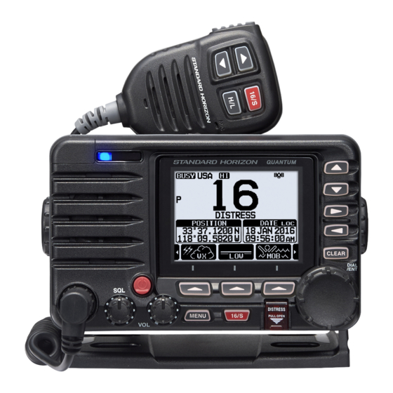
- Page 1 QUANTUM GX6500E/GX6000E 25 Watt VHF/FM Marine Transceiver Owner’s Manual...
-
Page 2: Table Of Contents
TABLE OF CONTENTS 7.11 PA/FOG OPERATION ..............48 Quick Reference Guide ................4 7.11.1 Operating the PA HAIL mode........49 1 GENERAL INFORMATION ..............5 7.11.2 Operating the FOG HORN mode .........50 2 PACKING LIST ..................6 7.11.3 Fog Signal Timing Chart ..........51 3 OPTIONAL ACCESSORIES ..............6 7.11.4 Operating the HORN mode ..........52 4 GETTING STARTED................7 4.1 PROHIBITED COMMUNICATIONS ..........7... - Page 3 TABLE OF CONTENTS 10.1 WAYPOINT OPERATION ............107 15.12.3 Setting for End of Tone ..........155 10.1.1 Starting and Stopping Navigation .......107 15.12.4 Data Erase..............156 15.13 SCRAMBLER SETUP ..............157 10.1.2 Setting Up Waypoint Directory ........109 10.1.3 Selecting the Display Range ........113 15.14 SUMMARY OF THE CANNEL FUNCTION SETUP ....158 10.1.4 Selecting the Arrival Range ........114 16 DSC SETUP ..................159 10.2 ROUTING OPERATION............115...
-
Page 4: Quick Reference Guide
uick efeRence uide The GX6500E/GX6000E is equipped with the E2O (Easy-To-Operate) menu system. Basic operation may be accomplished by following the procedure below: Press and hold the key to turn on or off the radio. The MODE/STATUS indicator indicates the status of the transceiver. RED: XXXXX. -
Page 5: General Information
1 GENERAL INFORMATION The STANDARD HORIZON GX6500E/GX6000E Marine VHF/FM Marine transceiver is designed to be used in USA, International, and Canadian Marine bands. The GX6500E/GX6000E can be operated from 11 to 16 VDC and has a switchable RF output power of 1 watt or 25 watts. -
Page 6: Packing List
2 PACKING LIST When the package containing the transceiver is first opened, please check it for the following contents: GX6500E/GX6000E Transceiver Hand Microphone Power Cord Mounting Bracket and Hardware Owner’s Manual DSC Warning Sticker Flush Mount Template ... -
Page 7: Getting Started
4 GETTING STARTED PROHIBITED COMMUNICATIONS The FCC prohibits the following communications: • False distress or emergency messages: • Messages to “any boat” except in emergencies and radio tests; • Messages to or from a vessel on land; • Transmission while on land; •... -
Page 8: Coaxial Cable
COAXIAL CABLE VHF antennas are connected to the transceiver by means of a coaxial cable – a shielded transmission line. Coaxial cable is specified by it’s diameter and construction. For runs less than 20 feet, RG-58/U, about 1/4 inch in diameter is a good choice. For runs over 20 feet but less than 50 feet, the larger RG-8X or RG-213/U should be used for cable runs over 50 feet RG-8X should be used. -
Page 9: Calling Another Vessel (Channel 16 Or 9)
8. Give your vessel’s description: length, design (power or sail), color and other distinguishing marks. The total transmission should not exceed 1 minute. 9. End the message by saying “OVER”. Release the microphone switch and listen. 10. If there is no answer, repeat the above procedure. If there is still no response, try another channel. -
Page 10: Making Telephone Calls
After a transmission, say “over,” and release the microphone’s push-to-talk (PTT) switch. When all communication with the other vessel is completed, end the last transmission by stating your Call Sign and the word “out.” Note that it is not necessary to state your Call Sign with each transmission, only at the beginning and end of the contact. -
Page 11: Automated Radio Check Service
AUTOMATED RADIO CHECK SERVICE In areas across the country, Sea Tow offers boaters a way to conduct radio checks. To use Sea Tow’s free Automated Radio Check service, simply tune your VHF radio to the appropriate channel for your location and conduct a radio check as you typically would. -
Page 12: What Is The Range For Ais Receivers
4.10 WHAT IS THE RANGE FOR AIS RECEIVERS? Since AIS uses similar frequencies as a marine VHF radio, it has similar radio reception capabilities - which are basically line of sight. This means that the higher the VHF antenna is mounted, the greater the reception area will be. Reception from Class A vessels that are 20 or even 30 miles away on open water is not uncommon as their antennas are mounted high off the water. -
Page 13: Installation
5 INSTALLATION SAFETY / WARNING INFORMATION This radio is restricted to occupational use, work related operations only where the radio operator must have the knowledge to control the exposure conditions of its passengers and bystanders by maintaining the minimum separation distance of 3 feet (1 m). -
Page 14: Mounting The Radio
MOUNTING THE RADIO 5.3.1 Supplied Mounting Bracket The supplied mounting bracket allows overhead or desktop mounting. Use a 13/64” (5.2 mm) bit to drill the holes to a surface which is more 0.4” (10 mm) thick and can support more than 3.3 lbs (1.5 kg) and secure the bracket with the supplied screws, spring washers, flat washers, and nuts. -
Page 15: Optional Mmb-84 Flush Mount Bracket
5.3.2 Optional MMB-84 Flush Mount Bracket 1. Use the supplied template to mark the location where the rectangular hole is to be cut. Confirm the space behind the dash or panel is deep enough to accommodate the transceiver (at least 6.7” (17 cm) deep). There should be at least 1/2”... -
Page 16: Electrical Connections
ELECTRICAL CONNECTIONS CAUTION Reverse polarity battery connections will damage the radio! Connect the power cord and antenna to the radio. Antenna and Power Supply connections are as follows: 1. Mount the antenna at least 3 feet (1 m) away from the radio. At the rear of the radio, connect the antenna cable. -
Page 17: Rear Panel
PA Speaker Connection Cable (Orange, Yellow, Green & Blue) Connects the GX6500E/GX6000E to PA speakers. See section “3 OPTION- AL ACCESSORIES” for a list of optional STANDARD HORIZON Speakers. Green: PA FWD Speaker (+) Blue: PA FWD Speaker (−) Orange: PA AFT Speaker (+) Yellow: PA AFT Speaker (−) - Page 18 Connects the radio to a DC power supply capable of delivering 11 to 16VDC. RAM4 Connector (SSM-70H Remote Station Microphone Connector) Connects the GX6500E/GX6000E to the SSM-70H (RAM4) Remote Station Microphone. Refer to section “19 SSM-70H (RAM4) REMOTE MIC OPERA- TION”...
-
Page 19: Connection Of External Devices To The Radio
CONNECTION OF EXTERNAL DEVICES TO THE RADIO 5.6.1 Connecting the SCU-31 External GPS Antenna to the Radio Connect the SCU-31 cable to the GPS ANT (six pin) connector on the rear panel, then tighten the cable nut (see illustration at the right). 5.6.2 Connecting the NMEA 0183/NMEA 0183-HS to the Radio External GPS Connections (NMEA 0183 4800 baud or NMEA 0183-HS... -
Page 20: Accessory Cables And Nmea 0183 Cables
manufacturer of the GPS receiver externally connected. If you have further inquires, please feel free to contact Product Support at: Phone: (800) 767-2450 Email: marinetech@yaesu.com 5.6.3 Accessory Cables and NMEA 0183 Cables The image and table below show the wires of the GX6500E/GX6000E and the connections to optional devices such as a external GPS antenna, GPS chart plotter and an AIS receiver or transponder. -
Page 21: Nmea 0813/Nmea 0183-Hs To Chart Plotter
5.6.4 NMEA 0813/NMEA 0183-HS to Chart Plotter 4800 Baud Connections GPS Antenna GPS Chart Plotter Radio Wires Plotter Connection Blue: NMEA IN ( ) No Connection Green: NMEA IN ( ) No Connection Gray: NMEA OUT ( ) NMEA IN ( ) Brown: NMEA OUT ( ) NMEA IN ( ) Yellow: NMEA-HS OUT ( ) - Page 22 38400 Baud Connections GPS Antenna GPS Chart Plotter Radio Wires Plotter Connection Blue: NMEA IN ( ) No Connection Green: NMEA IN ( ) No Connection Gray: NMEA OUT ( ) NMEA IN ( ) Brown: NMEA OUT ( ) NMEA IN ( ) Yellow: NMEA-HS OUT ( ) No Connection...
-
Page 23: Connection To External Gps Or Chart Plotter
5.6.5 Connection to External GPS or Chart Plotter 4800 Baud Connections GPS Receiver Radio Wires Plotter Connection Blue: NMEA IN ( ) NMEA OUT ( ) Green: NMEA IN ( ) NMEA OUT ( ) Gray: NMEA OUT ( ) NMEA IN ( ) Brown: NMEA OUT ( ) NMEA IN ( ) - Page 24 38400 Baud Connections GPS Receiver Radio Wires Plotter Connection Blue: NMEA IN ( ) NMEA OUT ( ) Green: NMEA IN ( ) NMEA OUT ( ) Gray: NMEA OUT ( ) NMEA IN ( ) Brown: NMEA OUT ( ) NMEA IN ( ) Yellow: NMEA-HS OUT ( ) No Connection...
-
Page 25: Connection To External Pa/Hail Speaker
5.6.6 Connection to External PA/HAIL Speaker GREEN PA FWD Speaker (horn) BLUE ORANGE PA AFT Speaker (horn) YELLOW External Speaker WHITE Wire Color/Description Connection Examples RED - External Speaker (+) Positive wire of external 4 Ohm External speaker WHITE - External Speaker (−) Negative wire of external 4 Ohm External speaker GREEN - PA FWD Speaker (+) Positive wire of external 4 Ohm audio speaker (horn) -
Page 26: Rear Microphone Installation
5.6.7 Rear Microphone Installation Connect the optional MEK-4 (micro- phone extension kit) to the Rear MIC (six pin) connector on the rear panel, then tighten the cable nut (see illustra- tion at the right). 5.6.8 Optional SSM-70H (RAM4) Installation The GX6500E/GX6000E is capable of using two SSM-70H (RAM4) Remote Station Microphones to remotely control the Radio, AIS, DSC and PA/Fog functions. - Page 27 6. Drill the four screw holes (approx. 2 mm) on the wall, then install the mount- ing base to the wall using four screws. 7. Put the rubber cap on to the nut. The installation is now complete. External Speaker Connections Ferrite Core Gasket Wall...
- Page 28 Connecting an External Speaker to the RAM4 Mic Cable In noisy locations and optional external speaker may be connected to the white speaker wires on the RAM4 routing cable. The RAM4 can drive the internal speaker or the external speaker one at a time. When connecting an external speaker, follow the procedure below to turn off the RAM4 audio and enable the external speaker wires on the RAM4 routing cable.
-
Page 29: Initial Setup Required When Turning On The Power For The First Time
INITIAL SETUP REQUIRED WHEN TURNING ON THE POWER FOR THE FIRST TIME 5.7.1 Setting the Welcome Screen and Region 5.7.2 Maritime Mobile Service Identity (MMSI) What is an MMSI? An MMSI is a nine digit number used on marine transceivers capable of using Digital Selective Calling (DSC). -
Page 30: Checking Gps Signal (Gps Status Display)
3. Press the [MMSI] soft key. 4. Rotate the DIAL/ENT knob to select the first number of your MMSI, then press the [SELECT] soft key to step to the next number. 5. Repeat step 4 to set your MMSI number (9 digits). 6. - Page 31 The GX6500E/GX6000E has a GPS status display which shows the satellites currently being received, along with a graphical (bar-graph) representation of the relative signal strengths from the satellites. (gps s tatus isplay MoDe NOTE For the GX6500E/GX6000E to properly show the GPS status page when an external GPS antenna or a chart plotter is connected it must be setup to output GSA and GSV NMEA 0183 sentences.
-
Page 32: Gps Configuration
GPS CONFIGURATION 5.9.1 Changing the Gps Time From the factory the GX6500E/GX6000E shows GPS satellite time or UTC (Universal Time Coordinated) time. A time offset is needed to show the local time in your area. The time offset must be changed in order for the radio to display the current time in your area. -
Page 33: Changing The Time Area
5.9.2 Changing the Time Area This menu selection allows the radio to show UTC time or local time with offset. 1. Press the MENU key to display “MENU”. 2. Rotate the DIAL/ENT knob to select “SETUP”, then press the [SELECT] soft key. 3. -
Page 34: Changing Cog To True Or Magnetic
5. Rotate the DIAL/ENT knob to select “24hour” or “12hour”. 6. Press the [ENTER] soft key to store the selected setting. 7. Press the CLEAR key to return to radio operation. 5.9.4 Changing Cog to True or Magnetic Allows the GPS COG (Course Over Ground) and the BRG from an AIS target to be selected to show in ON or OFF. -
Page 35: Controls And Indicators
6 CONTROLS AND INDICATORS This section defines each control of the transceiver. See illustration below for location of controls. For detailed operating instructions refer to chapter 8 of this manual. FRONT PANEL ... - Page 36 MENU key Press to access MENU. For details, refer to section “8.16 OPERATION MENU”. 16/S key Pressing this key immediately recalls channel 16 from any channel loca- tion. Holding down this key recalls the SUB channel (The default setting is channel 9).
-
Page 37: Microphone
MODE/STATUS indicator Indicates the radio status with the four colors on the three postions of the mode/status indicator. Postion Color Description Blue AIS-Board Working Purple Receiving MSG23 Left AIS-Board Failed AIS Transmitting (GX6500 Only) Center Orange TX Time Out (GX6500 Only) Green Data Receiving (registerd MMSI) Orange... - Page 38 When an optional RAM4 mic is connected and intercom mode is selected, pressing the PTT switch enables voice communications from the GX6500E/ GX6000E to the RAM4 second station microphone. Microphone speaker Audio heard through internal radio speaker is heard through speaker inside the microphone.
-
Page 39: Basic Operation
7 BASIC OPERATION TURNING ON AND OFF THE TRANSCEIVER 1. After the transceiver has been installed, ensure that the power supply and antenna are properly connected. 2. Press and hold the key to turn the radio on. 3. Press and hold the key again to turn the radio off. -
Page 40: Transmit Power
7.3.1 Transmit Power The TX output power of the GX6500E/GX6000E is set to high level (25W) in factory default, and the “[HI]” indicator is displayed on the top part of the screen. To switch the TX output power: 1. Press the ►/◄ key repeatedly until the [HI] or [LOW] soft key is displayed at the bottom of the screen. -
Page 41: International, Usa And Canada Mode
INTERNATIONAL, USA AND CANADA MODE To change the channel group from International to USA or Canada: 1. Press the MENU key to display “MENU”. 2. Rotate the DIAL/ENT knob to select “SETUP”, then press the [SELECT] soft key. 3. Rotate the DIAL/ENT knob to select “CHANNEL SETUP”, then press the [SELECT] soft key. -
Page 42: Multi Watch (To Priority Channel)
MULTI WATCH (TO PRIORITY CHANNEL) Multi watch is used to scan two or three channels for communications. • In Dual Watch, a normal VHF channel and the priority channel are scanned alternately. • In Triple Watch, a normal VHF channel, the priority channel, and the sub channel are scanned alternately. -
Page 43: Starting The Dual Watch
7.7.2 Starting the Dual Watch 1. Adjust the SQL knob until the background noise disappears. 2. Rotate the DIAL/ENT knob to select a channel you wish to watch. 3. Press ►/◄ key repeatedly until the [DUAL WATCH] soft key is displayed at the bottom of the screen, press the [DUAL WATCH] soft key. -
Page 44: Programming Scan Memory
4. Rotate the DIAL/ENT knob to select “SCAN TYPE”, then press the [SELECT] soft key. 5. Rotate the DIAL/ENT knob to select “PRIORITY” or “MEMORY”. 6. Press the [ENTER] soft key to store the selected setting. 7. Press the CLEAR key to return to radio operation. CH01A CH01A CH88A... -
Page 45: Memory Scanning (M-Scan)
7. To REMOVE a channel from the list, select the channel then press the [MEM] soft key. “ON” icon of the selected channel will disappear. 8. When you have completed your selection, press the CLEAR key to return to radio operation. To check channels to be scanned, rotate the DIAL/ENT knob. -
Page 46: Preset Channels: Instant Access
NOTE In the default setting, Channel 16 is set as the priority channel. You may change the priority channel to the desired channel from Channel 16 on the SETUP menu. Refer to section “16.7 PRIORITY CHANNEL”. PRESET CHANNELS: INSTANT ACCESS 10 preset channels can be programmed for instant access. -
Page 47: Operation
7.9.2 Operation 1. Press the ►/◄ key repeatedly, then press the [PRESET] soft key to recall the preset channel. The “[P-SET]” icon will appear on the display. 2. Rotate the DIAL/ENT knob to select the desired preset channel. 3. Press the [PRESET] soft key to return to the last selected channel. -
Page 48: Pa/Fog Operation
The GX6500E/GX6000E has a 30W hailer built-in and can be used with any 4 Ohm PA horn. Standard Horizon offers two HAIL/PA horns, the 220SW (5” round 30 Watt HAIL/PA horn) and the 240SW (5” x 8” rectangular 40 Watt HAIL/PA horn). -
Page 49: Operating The Pa Hail Mode
7.11.1 Operating the PA HAIL mode 1. Press the MENU key to display “MENU”. 2. Rotate the DIAL/ENT knob to select “PA FOG”, then press the [SELECT] soft key. 3. Rotate the DIAL/ENT knob to select “PUBLIC ADDRESS”, then press the [SELECT] soft key. 4. -
Page 50: Operating The Fog Horn Mode
7.11.2 Operating the FOG HORN mode The user can select the type of horn from “Underway”, “Stop”, “Sail”, “Towing”, “Aground” and “Anchor”. 1. Press the MENU key to display “MENU”. 2. Rotate the DIAL/ENT knob to select “PA FOG”, then press the [SELECT] soft key. -
Page 51: Fog Signal Timing Chart
7.11.3 Fog Signal Timing Chart TYPE PATTERN USAGE UNDERWAY One 5-second blasts every 120 seconds. Motor vessel underway and making way. Listen Back 120s STOP Two 5-second blasts (separated by 2 seconds) Motor vessel underway but every 120 seconds. stopped (not making way). Listen Back 120s SAIL... -
Page 52: Operating The Horn Mode
7.11.4 Operating the HORN mode The user can select the type of horn from “Horn” and “Siren”. 1. Press the MENU key to display “MENU”. 2. Rotate the DIAL/ENT knob to select “PA FOG”, then press the [SELECT] soft key. 3. -
Page 53: Calling
3. Rotate the DIAL/ENT knob to select the device to which you want to communicate, then press the [SELECT] soft key. The “” icon will appear at the left side of the selected station. 4. Repeat step 3 for all the desired devices. 5. -
Page 54: Demo Mode
7.14 DEMO MODE This mode is used by Standard Horizon sales persons and dealers to demon- strate radio, DSC and AIS functions. Demo mode allows latitude, longitude and time to be entered to simulate radio displays. When the demo mode is enabled, the radio display will automatically switch from the NORMAL, COMPASS, WAYPOINT, AIS and GM displays. -
Page 55: Operation Menu
9. Rotate the DIAL/ENT knob to select “DEMO START”, then press the [SELECT] soft key. 10. Rotate the DIAL/ENT knob to select “START”, then press the [SELECT] soft key. NOTE To stop the demo mode, select “STOP” in step 10 above. 7.15 OPERATION MENU The GX6500E/GX6000E provides advanced features... - Page 56 Your current location, course, and speed can be displayed in a numerical or compass style. You can also check the position and signal strength of captured GPS satellites. For details, refer to section “9 GPS OPERATION”. NAVI You can start navigation to a memorized or temporarily input waypoint. For details, refer to section “11 NAVIGATION”.
-
Page 57: Gps Operation
8 GPS OPERATION The GX6500E/GX6000E has the SCU-31 external GPS antenna (option) to receive and display the position information. Your position information as well as recieved positions can be memorized and utilized later for navigation. DISPLAYING POSITION INFORMATION 8.1.1 GPS Information Numerical Display 1. -
Page 58: Checking Gps Status
CHECKING GPS STATUS 1. Press the MENU key to display “MENU”. 2. Rotate the DIAL/ENT knob to select “GPS”, then press the [SELECT] soft key. 3. Rotate the DIAL/ENT knob to select “GPS STATUS”. 4. Press the [ENTER] soft key to display the GPS status currently being received. -
Page 59: Gps Logger Operation
GPS LOGGER OPERATION The GX6500E/GX6000E* includes a logger for position information that allows you to record your location at regular intervals. (* The GX6000 requires optional SCU-31 GPS Receiver.) 1. Press the [LOGGER] soft key to turn the function on or off. -
Page 60: Digital Selective Calling (Dsc)
9 DIGITAL SELECTIVE CALLING (DSC) GENERAL WARNING This GX6500E/GX6000E is designed to generate a digital maritime distress and safety call to facilitate search and rescue. To be effective as a safety device, this equipment must be used only within commu- nication range of a shore-based VHF marine channel 70 distress and safety watch system. -
Page 61: Dsc Distress Aleart
DSC DISTRESS ALEART The GX6500E/GX6000E is capable of transmitting and receiving DSC distress messages to all DSC radios. Distress calls from the GX6500E/GX6000E include the latitude and longitude of the vessel when the external GPS unit is activated. 9.2.1 Transmitting a DSC Distress Aleart NOTE To be able to transmit a DSC distress call an MMSI number must be programmed, refer to section “6.7.2 Maritime Mobile Service Identity... - Page 62 6. To turn off the distress alarm before the radio retransmits the distress aleart, press the 16/S key or the [QUIT] soft key. Transmitting a DSC Distress Alert with Nature of Distress The GX6500E/GX6000E is capable of transmitting a DSC distress alert with the following “Nature of Distress”...
- Page 63 4. Press the [POS/TM] soft key. 5. Rotate the DIAL/ENT knob to select the first number of latitude, then press the [SELECT] soft key to step to the next number. 6. Repeat step 5 to set the position and time. If a mistake was made, rotate the DIAL/ENT knob to select “←”...
-
Page 64: Receiving A Dsc Distress Aleart
Canceling a DSC Distress Aleart If a DSC distress aleart was sent by error the GX6500E/GX6000E allows you to send a message to other vessels to cancel the distress call that was made. 1. Press the [CANCEL] soft key, then press the [YES] soft key. - Page 65 [PAUSE]: Press this key to temporarily disable automatic switching to Channel 16. [QUIT]: Press this key to quit the automatic Channel 16 switching and revert to the last selected working channel. 4. After accepting the call, press the [TO WPT] soft key to set the vessel in distress as a destination for navigation.
-
Page 66: All Ships Call
ALL SHIPS CALL The all ships call function allows contact to be established with DSC equipped vessels without having their MMSI in the individual calling directory. Also, priority for the call can be designated as “Safety” or “Urgency”. SAFETY Call: This type of call is used to transmit boating safety information to other vessels. -
Page 67: Receiving An All Ships Call
7. After the all ships call is transmitted, the transceiver will switch to the selected channel. 8. Listen to the channel to make sure it is not busy, then key the microphone and say “PAN PAN, PAN PAN, PAN PAN” or “Securite, Securite, Securite” depending on the priority of the call. -
Page 68: Individual Call
4. Press the [QUIT] key to return to the channel display. NOTE When there is an unread all ships call, “ ” icon will appear on the display. You may review the unread all ships call from the DSC log, refer to the section “10.11.2 Reviewing a Logged DSC RX Distress Call”. - Page 69 5. Rotate the DIAL/ENT knob to select “ADD”, then press the [SELECT] soft key. 6. Rotate the DIAL/ENT knob to select “NAME:”, then press the [SELECT] soft key. 7. Rotate the DIAL/ENT knob to scroll through the first letter of the name of the vessel or person you want to reference in the directory.
-
Page 70: Setting Up The Individual Call Reply
9.4.2 Setting up the Individual Call Reply This menu item sets up the radio to automatically (default setting) or manually respond to a DSC individual call requesting you to switch to a working channel for voice communications. When “Manual” is selected the MMSI of the calling vessel is shown allowing you to see who is calling. -
Page 71: Transmitting An Individual Call
4. Rotate the DIAL/ENT knob to select “INDIVIDUAL ACK.”, then press the [SELECT] soft key. 5. Rotate the DIAL/ENT knob to select “ABLE” or “UNABLE”. 6. Press the [ENTER] soft key to store the selected setting. 7. Press the CLEAR key to return to radio operation. 9.4.4 Transmitting an Individual Call This feature allows the user to contact another vessel with a DSC radio. - Page 72 7. Press the [YES] soft key to transmit the individual DSC signal. 8. When an individual call acknowledgment is received, the established channel is automatically changed to the channel which is selected on step 6 above and a ringing tone sounds. 9.
-
Page 73: Receiving An Individual Call
7. When finished entering the MMSI number, press the [FINISH] soft key. 8. In the INTERSHIP CH list, rotate the DIAL/ENT knob to select the operating channel on which you want to communicate, then press the [SELECT] soft key. To select operating channels from all voice channels, press the [MANUAL] soft key. - Page 74 4. Press the [QUIT] soft key to return to radio operation. Manual reply: 1. When an individual call is received, an individual call ringing alarm sounds. The display shows the MMSI of the vessel transmitting the individual call. 2. Press any key to stop the alarm. 3.
-
Page 75: Setting Up The Individual Call Ringer
7. Press the [QUIT] soft key to return to the channel display. NOTE When there is an unread individual call, “ ” icon will appear on the display. You may review the unread individual call from the DSC log, refer to the section “10.11.2 Reviewing a Logged DSC RX Distress Call”. - Page 76 The GX6500E/GX6000E has the capability to turn off the individual call ringer. 1. Press the MENU key to display “MENU”. 2. Rotate the DIAL/ENT knob to select “SETUP”, then press the [SELECT] soft key. 3. Rotate the DIAL/ENT knob to select “DSC SETUP”, then press the [SELECT] soft key.
-
Page 77: Group Call
MMSI numbers. The first digit of a group MMSI is always set to “0” by International rules. All Standard Horizon radios are preset so when programming a group MMSI the first digit is set to “0”. - Page 78 3. Rotate the DIAL/ENT knob to select “DSC SETUP”, then press the [SELECT] soft key. 4. Rotate the DIAL/ENT knob to select “GROUP DIREC- TORY”, then press the [SELECT] soft key. 5. Rotate the DIAL/ENT knob to select “ADD”, then press the [SELECT] soft key.
-
Page 79: Transmitting A Group Call
11. Rotate the DIAL/ENT knob to select “MMSI:”, then press the [SELECT] soft key. 12. Rotate the DIAL/ENT knob to select the second number of the MMSI (nine digits: first digit perma- nently set to “0”) which you want to contact, then press the [SELECT] soft key to step to the next number. - Page 80 6. In the INTERSHIP CH list, rotate the DIAL/ENT knob to select the operating channel on which you want to communicate, then press the [SELECT] soft key. To select operating channels from all voice channels, press the [MANUAL] soft key. 7.
- Page 81 5. Rotate the DIAL/ENT knob to select the first number of the MMSI (nine digits: first digit permanently set to “0”) which you want to contact, then press the [SELECT] soft key to step to the next number. 6. Repeat step 5 to set the MMSI number. If a mistake was made entering in the MMSI number, rotate the DIAL/ENT knob to select “←”...
-
Page 82: Receiving A Group Call
9.5.3 Receiving a Group Call 1. When a group call is received, the GX6500E/ GX6000E will produce a ringing alarm sound. 2. The display shows the group MMSI number. 3. Press any key to stop the alarm. 4. Monitor the channel for the person calling the group for a message. -
Page 83: Setting Up The Group Call Ringer
9.5.4 Setting up the Group Call Ringer The GX6500E/GX6000E has the capability to turn off the group call ringer. 1. Press the MENU key to display “MENU”. 2. Rotate the DIAL/ENT knob to select “SETUP”, then press the [SELECT] soft key. 3. -
Page 84: Position Request
Advancements in DSC have made it possible to poll the location of another vessel and show the position of that vessel on the display of the GX6500E/ GX6000E. Standard Horizon has taken this feature one step further, if any compatible GPS chart plotter is connected to the GX6500E/GX6000E, the polled position of the vessel is shown on the display of the GPS chart plotter making it easy to navigate to the location of the polled vessel. -
Page 85: Transmitting A Position Request To Another Vessel
5. Rotate the DIAL/ENT knob to select “AUTO” or “MANUAL”. In “AUTO” mode, after a DSC POS request is received, the radio will automatically transmit your vessel’s position. In “MANUAL” mode, the display of the GX6500E/GX6000E will show who is requesting the position and the [YES] soft key on radio has to be pressed to send your position to the requesting vessel. - Page 86 8. Press the [QUIT] soft key to return to radio operation. NOTE If the GX6500E/GX6000E does not receive position data from the polled vessel, the display will show “NO POSITION DATA”. Position Request by Manually Entering an MMSI This feature allows you to request the position of a vessel by manually enter- ing the MMSI.
-
Page 87: Receiving A Position Request
8. Press the [YES] soft key to transmit the position request DSC call. 9. When the GX6500E/GX6000E receives the position from the polled vessel it is shown on the radio display. 10. Press the [QUIT] soft key to return to radio operation. NOTE The received position from the polled vessel can be transferred to a GPS chart plotter via NMEA DSC and DSE sentences. -
Page 88: Manual Input Of Position Information
9.6.4 Manual Input of Position Information If the GX6500E/GX6000E is located in an area where GPS reception is limited when you are going to reply to the received position request, you may manually input your location (latitude and longitude) and time to be sent. 1. -
Page 89: Setting Up A Position Request Ringer
9.6.5 Setting up a Position Request Ringer The GX6500E/GX6000E has the capability to turn off the position request ringer. 1. Press the MENU key to display “MENU”. 2. Rotate the DIAL/ENT knob to select “SETUP”, then press the [SELECT] soft key. 3. -
Page 90: Position Report
POSITION REPORT The feature is similar to position request, however instead of requesting a position of another vessel this function allows you to send your position to another vessel. 9.7.1 Transmitting a DSC Position Report Call DSC Position Report Call using the Individual/Position Directory Refer to section “10.4 INDIVIDUAL CALL”... - Page 91 DSC Position Report Call by Manually Entering an MMSI This feature allows you to send your position to another vessel by manually entering the MMSI of the ship you want to send your position to. 1. Press the MENU key to display “MENU”. 2.
-
Page 92: Receiving A Dsc Position Report Call
9.7.2 Receiving a DSC Position Report Call When another vessel transmits their vessels location to the GX6500E/GX6000E the following will happen: 1. When a position report call is received from another vessel, a ringing sound will be produced. 2. Press any key to stop ringing. 3. -
Page 93: Saving The Reported Position As A Waypoint
Stopping Navigation to the Reported Position 1. Press one of the soft keys to show the key selections. 2. Press the [STOP] soft key. The radio will stop navigat- ing to the waypoint and the normal VHF display will be shown. 9.7.4 Saving the Reported Position as a Waypoint The GX6500E/GX6000E can save a position report call in the radio’s memory... -
Page 94: Setting Up A Position Report Ringer
9.7.5 Setting up a Position Report Ringer The GX6500E/GX6000E has the capability to turn off the position report ringer. 1. Press the MENU key to display “MENU”. 2. Rotate the DIAL/ENT knob to select “SETUP”, then press the [SELECT] soft key. 3. -
Page 95: Polling Call
POLLING CALL The GX6500E/GX6000E has the capability to track another vessel. 9.8.1 Transmitting a Polling Call to a Vessel Polling Call using the Individual/Position Call Directory 1. Press the MENU key to display “MENU”. 2. Rotate the DIAL/ENT knob to select “DSC CALL”, then press the [SELECT] soft key. - Page 96 Polling Call by Manually Entering an MMSI This feature allows you to contact a vessel by manually entering the MMSI of the ship you want to track. 1. Press the MENU key to display “MENU”. 2. Rotate the DIAL/ENT knob to select “DSC CALL”, then press the [SELECT] soft key.
-
Page 97: Receiving A Polling Call
9.8.2 Receiving a Polling Call When another vessel transmits a polling call to the GX6500E/GX6000E the following will happen: 1. When a polling call is received, the radio will automati- cally respond to the calling vessel. 2. To exit from the polling call display, press the [QUIT] soft key. -
Page 98: Setting Up The Polling Time Interval
9.9.2 Setting up the Polling Time Interval 1. Press the MENU key to display “MENU”. 2. Rotate the DIAL/ENT knob to select “SETUP”, then press the [SELECT] soft key. 3. Rotate the DIAL/ENT knob to select “DSC SETUP”, then press the [SELECT] soft key. 4. -
Page 99: Enabling/Disabling Auto Pos Polling
4. Rotate the DIAL/ENT knob to select “SELECTED ID”, then press the [SELECT] soft key. 5. The radio will show a blank row highlighted when you select the vessel for the first time. Press the [SELECT] soft key. 6. The radio will show the vessels programmed in the individual directory. -
Page 100: Dsc Test
7. Auto POS Polling starts and “[A]” icon will light up on the screen. 9.10 DSC TEST This function is used to contact another DSC equipped vessel to ensure the DSC functions of the radio are operating. NOTE To use this feature, the radio that will receive the test call also needs to have the DSC Test feature. - Page 101 6. Press the [YES] soft key to transmit the DSC test call to the other vessel. 7. Press the [QUIT] soft key to return to radio operation. DSC Test Call by Manually Entering an MMSI 1. Press the MENU key to display “MENU”. 2.
-
Page 102: Receiving A Dsc Test Call
NOTE After the radio receives a test call reply from the vessel that was called, the radio will ring and show “RX TEST CALL” display, which confirms the radio you called has received the test call. 9.10.3 Receiving a DSC Test Call When another vessel transmits a DSC Test call to the GX6500E/GX6000E the following will happen: 1. -
Page 103: Reviewing A Logged Dsc Rx Distress Call
3. Rotate the DIAL/ENT knob to select “DSC LOG”, then press the [SELECT] soft key. 4. Rotate the DIAL/ENT knob to select “TRANSMITTED”, then press the [SELECT] soft key. 5. Rotate the DIAL/ENT knob to select the station (name or MMSI number) you want to review and/or resend the call. -
Page 104: Reviewing Other Logged Calls
5. Rotate the DIAL/ENT knob to select the station (name or MMSI number) you want to review and/or relay the distress call to other vessels. Note: When there is an unread received call, “ ” icon will appear at the head of the call’s row. 6. -
Page 105: Deleting Logged Calls From The Dsc Log Directory
9.11.4 Deleting Logged Calls from the DSC Log Directory 1. Press the MENU key to display “MENU”. 2. Rotate the DIAL/ENT knob to select “DSC CALL”, then press the [SELECT] soft key. 3. Rotate the DIAL/ENT knob to select “DSC LOG”, then press the [SELECT] soft key. -
Page 106: Dsc Loop Back Operation
9.12 DSC LOOP BACK OPERATION The GX6500E/GX6000E has a self-test feature for DSC call. 1. Press the MENU key to display “MENU”. 2. Rotate the DIAL/ENT knob to select “DSC CALL”, then press the [SELECT] soft key. 3. Rotate the DIAL/ENT knob to select “DSC LOOP BACK”, then press the [SELECT] soft key. -
Page 107: Navigation
10 NAVIGATION The GX6500E/GX6000E is capable of storing up to 250 waypoints for naviga- tion using the compass page. You can also navigation to DSC distress calls with position or a position received from another DSC radio using DSC polling. 10.1 WAYPOINT OPERATION 10.1.1... - Page 108 Navigation by Manually Entering a Waypoint 1. Press the MENU key to display “MENU”. 2. Rotate the DIAL/ENT knob to select “NAVI”, then press the [SELECT] soft key. 3. Rotate the DIAL/ENT knob to select “WAYPOINT”, then press the [SELECT] soft key. 4.
-
Page 109: Setting Up Waypoint Directory
The navigation screen will appear. The screen includes the distance and direction to the destination, and the waypoint is indicated by a dot () inside the compass. 11. Press one of the soft keys to show the key selections. Press the [STOP] soft key to stop the navigation. 10.1.2 Setting Up Waypoint Directory Marking a Position... - Page 110 8. Rotate the DIAL/ENT knob to select “SAVE”, then press the [SELECT] soft key to save the mark posi- tion into memory. 9. Press the CLEAR key to return to radio operation. Adding a Waypoint 1. Press the MENU key to display “MENU”. 2.
- Page 111 Editing a Waypoint This function allows a previously entered waypoint to be edited. 1. Press the MENU key to display “MENU”. 2. Rotate the DIAL/ENT knob to select “SETUP”, then press the [SELECT] soft key. 3. Rotate the DIAL/ENT knob to select “WAYPOINT SETUP”, then press the [SELECT] soft key.
- Page 112 Deleting a Waypoint 1. Press the MENU key to display “MENU”. 2. Rotate the DIAL/ENT knob to select “SETUP”, then press the [SELECT] soft key. 3. Rotate the DIAL/ENT knob to select “WAYPOINT SETUP”, then press the [SELECT] soft key. 4.
-
Page 113: Selecting The Display Range
10.1.3 Selecting the Display Range This menu item allows setting of the range on the compass display. 1. Press the MENU key to display “MENU”. 2. Rotate the DIAL/ENT knob to select “SETUP”, then press the [SELECT] soft key. 3. Rotate the DIAL/ENT knob to select “WAYPOINT SETUP”, then press the [SELECT] soft key. -
Page 114: Selecting The Arrival Range
10.1.4 Selecting the Arrival Range This menu item allows setting of the range within which the GX6500E/GX6000E determines to be around the destination. 1. Press the MENU key to display “MENU”. 2. Rotate the DIAL/ENT knob to select “SETUP”, then press the [SELECT] soft key. -
Page 115: Routing Operation
10.2 ROUTING OPERATION The GX6500E/GX6000E allows you to set 1 to 15 waypoints along the route. Via14 Via15 Via3 Via2 Via1 Current position outing to a aypoint 10.2.1 Setting Up Routing Directory NOTE All the destinations and via-points must be programmed as waypoints in the GX6500E/GX6000E memory. - Page 116 6. Rotate the DIAL/ENT knob to select “NAME:”, then press the [SELECT] soft key. 7. Enter the route name by rotating the DIAL/ENT knob and the [SELECT] soft key. When finished entering the name (using fifteen char- acters or less), press the [FINISH] soft key. 8.
- Page 117 4. Rotate the DIAL/ENT knob to select “ROUTE DIREC- TORY”, then press the [SELECT] soft key. 5. Rotate the DIAL/ENT knob to select “EDIT”, then press the [SELECT] soft key. 6. Rotate the DIAL/ENT knob to select the route to be edited, then press the [SELECT] soft key to show the route input display.
-
Page 118: Starting And Stopping Route Navigation
6. Rotate the DIAL/ENT knob to select the route to be deleted, then press the [SELECT] soft key. 7. Confirm the route to be deleted, rotate the DIAL/ENT knob to select “OK”, then press the [SELECT] soft key. 8. Press the CLEAR key to return to radio operation. 10.2.2 Starting and Stopping Route Navigation 1. -
Page 119: Changing The Destination
10.2.3 Changing the Destination 1. On the navigation screen, press one of the soft keys to show the key selections. 2. Press the [NEXT TG] soft key. 3. Rotate the DIAL/ENT knob to select desired destina- tion, then press the [SELECT] soft key. 4. -
Page 120: Gm Operation
11 GM OPERATION The GM (Group Monitor) feature of the GX6500E/GX6000E utilizes the same system as the DSC Group call and Auto Position Polling, to display the group members' locations. 11.1 SETTING UP GM OPERATION The GX6500E/GX6000E is capable of storing up to 10 groups with 1 to 9 members each. - Page 121 6. Rotate the DIAL/ENT knob to select “NAME:”, then press the [SELECT] soft key. 7. Enter the route name by rotating the DIAL/ENT knob and the [SELECT] soft key. When finished entering the name (using ten charac- ters or less), press the [FINISH] soft key. 8.
-
Page 122: Setting Up The Polling Time Interval
11.1.2 Setting Up the Polling Time Interval 1. Press the MENU key to display “MENU”. 2. Rotate the DIAL/ENT knob to select “SETUP”, then press the [SELECT] soft key. 3. Rotate the DIAL/ENT knob to select “GM SETUP”, then press the [SELECT] soft key. 4. -
Page 123: Starting Gm Operation
5. Rotate the DIAL/ENT knob to select the desired transmission type, then press the [ENTER] soft key. OFF: Disables the transmission during GM operation. ON GM: Enables the transmission during the GM target display. ON ALL: Enables the transmission during the GM operation. 6. -
Page 124: Changing The Gm Group Being Monitored
11.2.1 Changing the GM Group Being Monitored 1. On the GM target display, press one of the soft keys to show the key selections. 2. Press the [TG LIST] soft key. 3. Press the [CHG GP] soft key. 4. Rotate the DIAL/ENT knob to select the name of the group you want to start monitoring, then press the [ENTER] soft key. -
Page 125: Starting Navigation To A Group Member
11.2.3 Starting Navigation to a Group Member 1. On the GM target display, press one of the soft keys to show the key selections. 2. Press the [TG LIST] soft key. 3. Rotate the DIAL/ENT knob to select a member you want to approach. -
Page 126: Automatic Identerification System (Ais)
12 AUTOMATIC IDENTERIFICATION SYSTEM (AIS) 12.1 GENERAL NOTE • The GX6500E/GX6000E is equipped with an antenna jack designated for AIS. By connecting a marine antenna to this jack, the transceiver can receive AIS signals while receiving a voice channel signals. •... -
Page 127: Ais Operation
12.2 AIS OPERATION The GX6500E/GX6000E is equipped with an AIS receiver and can display AIS targets around your vessel on the radios display. Therefore, you can identify and avoid other large vessels nearby your vessel. NOTE To show AIS targets on the radio’s display, the SCU-31 or external GPS needs to be fixed own location so the radio knows its position relative to the AIS targets. - Page 128 [FUNC]: Press this key to show the function menu. 2. Press the [TG LIST] soft key to show a list of AIS target being received. 3. Rotate the DIAL/ENT knob to select the MMSI number (or vessel name). then press the [SELECT] soft key. Pressing the [DANGER] soft key changes the order to the TCPA time order.
-
Page 129: Changing The Ais Range
12.2.2 Changing the AIS Range 1. On the AIS screen, press one of the soft keys to show the key selections. 2. Press the [RANGE] soft key. Press the soft keys at the center and right side to select the radius range to display on the AIS screen. -
Page 130: Cpa/Tcpa Alarm Functions
6. To transmit an individual DSC call to the select AIS ship, press the [YES] soft key. After the GX6500E/GX6000E transmits, the radio waits for the DSC radio on the AIS ship to transmit a reply, at which time the radio will ring like a telephone. Pick up the mic, press the PTT switch and hail the AIS vessel. -
Page 131: Changing The Compass Display
12.2.5 Changing the Compass Display The compass display can be switched between “COURSE-UP” and “NORTH- UP”. The default setting is “COURSE-UP”. Refer to section “18.2 DISPLAY DIRECTION” for details. 12.3 AIS SETUP 12.3.1 Transponder (Only for GX6500) Enable/disable the AIS transponder. The default setting is “OFF”. 1. - Page 132 3. Rotate the DIAL/ENT knob to select “AIS SETUP”. 4. Rotate the DIAL/ENT knob to select “VESSEL INFO”, then press the [SELECT] soft key. 5. Rotate the DIAL/ENT knob to select “VESSEL NAME:”, then press the [SELECT] soft key. 6. Rotate the DIAL/ENT knob to scroll through the first letter of the name of the vessel you want to reference in the directory.
-
Page 133: Cpa
15. Rotate the DIAL/ENT knob to select “GPS ANT POS:”, then press the [SELECT] soft key. 16. Refer to steps 6 through 8, input the installation loca- tion of the GPS antenna on your ship. After entering all information, press the [FINISH] soft key. Next, select the type of your ship. -
Page 134: Tcpa
4. Rotate the DIAL/ENT knob to select “CPA”, then press the [SELECT] soft key. 5. Rotate the DIAL/ENT knob to select the distance you want the radio to alert you of an approaching AIS fitted vessel. You can select one from “0.5nm”, “1nm”, “2nm”, “5nm”, or “10nm”... -
Page 135: Cpa/Tcpa Alarm
12.3.5 CPA/TCPA Alarm Enable/disable the CPA/TCPA alarm functions. The default setting is “OFF”. 1. Press the MENU key to display “MENU”. 2. Rotate the DIAL/ENT knob to select “SETUP”, then press the [SELECT] soft key. 3. Rotate the DIAL/ENT knob to select “AIS SETUP”, then press the [SELECT] soft key. -
Page 136: Nmea 2000 Setup
13 NMEA 2000 SETUP Set the device numbers and system numbers of devices connected to the NMEA 2000 network. 13.1 SELECT DIVICE Select the device for which you want to set the device number and system number. 1. Press the MENU key to display “MENU”. 2. -
Page 137: System Instance
4. Rotate the DIAL/ENT knob to select “DEVICE INSTANCE”, then press the [SELECT] soft key. 5. Rotate the DIAL/ENT knob to select the first digit of the device number, then press the [SELECT] soft key to step to the next number. 6. -
Page 138: Summary Of The Nmea 2000 Setup
8. When finished programming the system number, press the [FINISH] soft key. 9. Press the CLEAR key to return to radio operation. 13.4 SUMMARY OF THE NMEA 2000 SETUP Item Description Default Value SELECT DEVICE Select the device for which you want to set −... - Page 139 − − 129796 AIS Acknowledge − − 129797 AIS Binary Broadcast Message − − 129798 AIS SAR Aircraft Position Report − − 129799 Radio Frequency/Mode/Power 129801 AIS Addressed Safety Related − − Message 129802 AIS Safety Related Broadcast − − Message −...
-
Page 140: Configuration Setup
14 CONFIGURATION SETUP 14.1 DISPLAY MODE The display mode can be selected according to the time of day you operate the radio. 1. Press the MENU key to display “MENU”. 2. Rotate the DIAL/ENT knob to select “SETUP”, then press the [SELECT] soft key. 3. -
Page 141: Dimmer Adjustment
14.2 DIMMER ADJUSTMENT This menu selection adjusts the backlight intensity. 1. Press the MENU key to display “MENU”. 2. Rotate the DIAL/ENT knob to select “SETUP”, then press the [SELECT] soft key. 3. Rotate the DIAL/ENT knob to select “CONFIGURA- TION”, then press the [SELECT] soft key. -
Page 142: Key Beep
14.4 KEY BEEP This selection is used to select the beep tone volume level when a key is pressed. 1. Press the MENU key to display “MENU”. 2. Rotate the DIAL/ENT knob to select “SETUP”, then press the [SELECT] soft key. 3. -
Page 143: Listen Back
5. Rotate the DIAL/ENT knob to select the desired level. The frequency level can be set from “200Hz” to “850Hz” (“400Hz” is default). 6. Press the [ENTER] soft key to store the selected setting. 7. Press the CLEAR key to return to radio operation. NOTE By default the radio Fog frequency is set to 400 Hz. - Page 144 4. Rotate the DIAL/ENT knob to select “STATION NAME”, then press the [SELECT] soft key. 5. With the second station microphone connected, rotate the DIAL/ENT knob to select the unit to be named, then press the [SELECT] soft key. 6. Rotate the DIAL/ENT knob to select to scroll through the first letter of the new station name.
-
Page 145: Soft Keys
14.8 SOFT KEYS From this menu, you can assign desired functions to each soft key from numbers 01 to 12. You can also set how long the soft key icon will be displayed after the corresponding soft key is pressed. 14.8.1 Key Assignment 1. -
Page 146: Key Timer
SOFT KEY NUMBERS DISPLAY FUNCTION ASSIGNED AS DEFAULT (See the previous page.) NONE − − TX HI/LO Selects transmit power. WX/CH Switches channels between weather and marine. SCAN Turns on or off scanning function. DUAL WATCH Starts and stops dual watch scan. MARK POSITION Marks the current position for a “Waypoint”. -
Page 147: Reset
6. Rotate the DIAL/ENT knob to select the desired time. 7. Press the [ENTER] soft key to store the selected setting. 8. Press the CLEAR key to return to radio operation. 14.9 RESET You may initialize the memories and settings of the setup categories indepen- dently or return the transceiver to the original factory setting. -
Page 148: Summary Of The Configuration Setup
14.10 SUMMARY OF THE CONFIGURATION SETUP Item Description Default Value DISPLAY MODE Toggles LCD display mode between DAY MODE daytime and nighttime mode DIMMER Adjusts the backlight level of the LCD and keypad CONTRAST Adjusts the contrast of the LCD KEY BEEP Adjusts the volume of beep tone when a key is pressed... -
Page 149: Channel Function Setup
15 CHANNEL FUNCTION SETUP 15.1 CHANNEL GROUP This menu item allows you to select a channel group from USA, Canada, and International. Refer to section “8.6 USA, INTERNATIONAL, AND CANADA MODE” for details. 15.2 WEATHER ALERT Enables/disables the NOAA Weather Alert function. The default setting is “OFF”. 1. -
Page 150: Scan Resume
15.5 SCAN RESUME This selection is used to select the time the GX6500E/GX6000E waits after a transmission ends before the radio starts to scan channels again. The default setting is 2 seconds. 1. Press the MENU key to display “MENU”. 2. -
Page 151: Sub Channel
5. Rotate the DIAL/ENT knob to select the desired chan- nel to be a priority. 6. Press the [ENTER] soft key to store the new setting. 7. Press the CLEAR key to return to radio operation. 15.8 SUB CHANNEL By default the sub channel is set to Channel 9. This procedure allows the radio to assign a different sub channel for instant access. -
Page 152: Noise Cancellation
5. Rotate the DIAL/ENT knob to select the channel to be named, then press the [SELECT] soft key. 6. Rotate the DIAL/ENT knob to scroll through the first letter of the new channel name. 7. Press the [SELECT] soft key to store the first letter in the name and step to the next letter to the right. -
Page 153: Audio Filter Operation
5. Rotate the DIAL/ENT knob to select “TX MODE”, then press the [SELECT] soft key. 6. Rotate the DIAL/ENT knob to select “ON” or “OFF”, then press the [ENTER] soft key. 7. Rotate the DIAL/ENT knob to select “RX MODE”, then press the [SELECT] soft key. -
Page 154: Rx Recorder
15.12 RX RECORDER Configure settings of the function for recording received voices. 15.12.1 RX Recorder Function ON/OFF Enable/disable the RX Recorder function. The default setting is “OFF”. 1. Press the MENU key to display “MENU”. 2. Rotate the DIAL/ENT knob to select “SETUP”, then press the [SELECT] soft key. -
Page 155: Setting For End Of Tone
5. Rotate the DIAL/ENT knob to select “RECORDING DELAY TIME”, then press the [SELECT] soft key. 6. Rotate the DIAL/ENT knob to select the desired delay time. The delay time can be set to “1sec” through “5sec”. 7. Press the [ENTER] soft key to store the new setting. 8. -
Page 156: Data Erase
15.12.4 Data Erase Delete recorded voice data. 1. Press the MENU key to display “MENU”. 2. Rotate the DIAL/ENT knob to select “SETUP”, then press the [SELECT] soft key. 3. Rotate the DIAL/ENT knob to select “CHANNEL SETUP”, then press the [SELECT] soft key. 4. -
Page 157: Scrambler Setup
15.13 SCRAMBLER SETUP Configure the voice scrambler setting. Two types of voice scrambler functions are available: the 4-code type (CVS2500A compatible) and the 32-code type (FVP-42 compatible for Furuno Electric FM-4721) (This function is not avail- able for CH16 and CH70). NOTE Operates only when the optional scrambler function is enabled. -
Page 158: Summary Of The Cannel Function Setup
9. Rotate the DIAL/ENT knob to select the scrambler code. The scrambler code can be set from “00” to “03” or “OFF” (While FVP-42 is selected in step 6, the scrambler code can be set from “00” to “32” or “OFF”). -
Page 159: Dsc Setup
16 DSC SETUP 16.1 INDIVIDUAL DIRECTORY The GX6500E/GX6000E has a DSC directory that allows you to store a vessel or person’s name and the associated MMSI you wish to contact via individual calls, position requests and position report transmissions. To transmit an individual call you must program this directory with information of the vessel you wish to contact, similar to a cellular phones telephone directory. -
Page 160: Position Reply
16.6 POSITION REPLY The GX6500E/GX6000E can be set up to automatically (default setting) or manually send your position when requested by another vessel. This selection is important if you are concerned about someone polling the position of your vessel that you may not want to. In the manual mode you will see the MMSI (Maritime Mobile Service Identity Number) or persons name shown on the display allowing you to choose to send your position to the requesting vessel. -
Page 161: No Action Timer
5. Rotate the DIAL/ENT knob to select the desired time, then press the [ENTER] soft key. 6. Press the CLEAR key to return to radio operation. When the “OFF” is selected, “[C]” icon will light up on the screen. 16.10 NO ACTION TIMER If no key is pressed during the “MENU”... -
Page 162: Wait Time For Position Fix
16.11 WAIT TIME FOR POSITION FIX This menu allows you to select the maximum wait time till obtaining a position information when receiving a distress call, POS Report call, or acknowledge- ment to POS request call. The default selection is 15 seconds. 1. -
Page 163: Summary Of The Dsc Setup Menu
16.13 SUMMARY OF THE DSC SETUP MENU Item Description Default Value INDIVIDUAL Enter or edit addresses used for individual − DIRECTORY call INDIVIDUAL REPLY Selects a reply to individual call MANUAL INDIVIDUAL ACK. Selects the message to be sent automati- ABLE cally as an individual call acknowledge- ment... -
Page 164: Gps Setup
17 GPS SETUP The “GPS Setup” mode allows the parameters for the SCU-31 external GPS antenna (option) to be customized for your operating requirements. 17.1 ORDER OF PRIORITY Specify the order of priority of the connection devices to be used when obtain- ing location information. -
Page 165: Display Direction
NOTE After setting the “PRIMARY” and “SECONDARY” devices, the last device will be displayed as “THIRDLY”. “THIRDLY” is set automatically and you cannot specify the “THIRDLY” device. 17.2 DISPLAY DIRECTION This menu item selects the compass direction to be shown on the GX6500E/ GX6000E display. -
Page 166: Time Offset
5. Rotate the DIAL/ENT knob to select the desired coor- dinate system. The location format can be selected from “ddd°mm.mmmm” and “ddd°mm’ss””. 6. Press the [ENTER] soft key to save the new setting. 7. Press the CLEAR key to return to radio operation. 17.4 TIME OFFSET Sets the local time offset between UTC (Universal Time Coordinated) and local... -
Page 167: Magnetic Variation
7. Rotate the DIAL/ENT knob to select the unit. 8. Press the [ENTER] soft key to store the new setting. 9. Press the CLEAR key to return to radio operation. 17.8 MAGNETIC VARIATION This selection allows customizing the GPS COG (Course Over Ground) indica- tion on the normal and compass pages and BRG on the waypoint and AIS pages. -
Page 168: Output Sentences
6. Rotate the DIAL/ENT knob to select the desired speed from “4800bps” and “38400bps”. 7. Press the [ENTER] soft key to save the new setting. 8. Press the CLEAR key to return to radio operation. 17.9.2 Output Sentences This selection is used to setup the NMEA output sentences of the GX6500E/ GX6000E. -
Page 169: Option Gps Unit
17.10 OPTION GPS UNIT Change the OPTION GPS UNIT setting. 17.10.1 Unit Power When you use the optional Standard Horizon GPS Antenna (SCU-31), set this selection to “ON”. The default setting is “OFF”. 1. Press the MENU key to display “MENU”. -
Page 170: Position Data Output
6. Rotate the DIAL/ENT knob to select “OFF” or “ON”. 7. Press the [ENTER] soft key to store the new setting. 8. Press the CLEAR key to return to radio operation. 17.10.2 Position Data Output Select the connection device to be used when outputting position data. 1. -
Page 171: Pinning
17.10.3 Pinning This selection is used to enable or disable position updates when the vessel is not underway. The default setting is “ON”. 1. Press the MENU key to display “MENU”. 2. Rotate the DIAL/ENT knob to select “SETUP”, then press the [SELECT] soft key. -
Page 172: Logger Interval
4. Rotate the DIAL/ENT knob to select “OPTION GPS UNIT”, then press the [SELECT] soft key. 5. Rotate the DIAL/ENT knob to select “DIFFERENTIAL GPS”, then press the [SELECT] soft key. 6. Rotate the DIAL/ENT knob to select “OFF” or “ON”. 7. -
Page 173: Log Erase
17.10.6 Log Erase 1. Press the MENU key to display “MENU”. 2. Rotate the DIAL/ENT knob to select “SETUP”, then press the [SELECT] soft key. 3. Rotate the DIAL/ENT knob to select “GPS SETUP”, then press the [SELECT] soft key. 4. -
Page 174: Summary Of The Gps Setup
17.11 SUMMARY OF THE GPS SETUP Item Description Default Value ORDER OF Sets the order of priority of the connec- PRIMARY: PRIORITY tion devices when obtaining position OPTION GPS information SECONDARY: NMEA 2000 THIRLDLY: NMEA 0183 COMPASS Selects the compass direction to be COURSE-UP DIRECTION displayed... -
Page 175: Ssm-70H ( Ram4 ) Remote Mic Operation
18 SSM-70H ( RAM4 ) REMOTE MIC OPERATION When a remote microphone is connected to the GX6500E/GX6000E, all VHF, DSC, setup menus, AIS, Navigation, GM (Group Monitor) functions and PA/ Fog modes can be remotely operated. The SSM-70H’s operation is same as GX6500E/GX6000E except the receiver audio volume setting and squelch level setting. - Page 176 DIAL/ENT knob While the normal screen is displayed, rotate the DIAL/ENT knob to select your desired channel. While the MENU screen is displayed, rotate the knob to select your desired menu item. econDary use Press this knob to enter a selection in the MENU. ...
- Page 177 Display 222 by 162 pixels full dot matrix display. Soft keys These three programmable keys can be customized through the setup menu mode. When pressing one of these keys briefly, the key functions will appear at the bottom of the display. Refer to section “19.2 RAM4 SOFT KEY ASSIGNMENT”...
-
Page 178: Ram4 Soft Key Assignment
18.2 RAM4 SOFT KEY ASSIGNMENT From this menu, you can assign desired functions to each RAM4 soft key from numbers 01 to 12. You can also set how long the soft key icon will be displayed after the corresponding soft key is pressed. The keys maybe setup to control the following functions: SOFT KEY NUMBERS DISPLAY... -
Page 179: Key Assignment
18.2.1 Key Assignment Configure all settings on the SSM-70H (RAM4) remote mic for which you want to assign functions to soft keys. 1. On the RAM4 mic, press the MENU key to display “MENU”. 2. Rotate the DIAL/ENT knob to select “SETUP”, then press the [SELECT] soft key. -
Page 180: Connecting A Usb Data Terminal To The Pc
Phone: (800) 767-2450 Email: marinetech@yaesu.com You can also download the log data from the radio by using the PC Program- ming Software which may be downloaded from the Standard Horizon website. The PC Programming Software is compatible with Windows ®... -
Page 181: Maintenance
Ensure that the supply voltage to the transceiver does not exceed 16 VDC or fall below 11 VDC. • Use only STANDARD HORIZON approved accessories and replacement parts. In the unlikely event of serious problems, please contact your Dealer or our repair facility. -
Page 182: Factory Service
20.2 FACTORY SERVICE In the unlikely event that the radio fails to perform or needs servicing, please contact the following: Standard Horizon Attention Marine Repair Department 6125 Phyllis Drive, Cypress, California 90630, U.S.A. Telephone (800) 366-4566 For repairs in Canada... - Page 183 Your position is not SCU-31 cable. Check the SCU-31 cable connection. displayed. Accessory cable. Check the accessory cable connection. Some GPS use the battery ground for NMEA connection. Setting of the GPS chart Check the output signal format of the GPS plotter.
-
Page 184: Atis Setup
21 ATIS SETUP The GX6500E/GX6000E supports the ATIS (Automatic Transmitter Identifica- tion System) used in Inland waterways in Europe. When enabled ATIS mode transmits a unique ATIS code each time the PTT switch is released at the end of a transmission. Users should check with their local marine regulatory authority in their country for assistance in obtaining an ATIS code. -
Page 185: Atis Ch Group
21.2 ATIS CH GROUP The GX6500E/GX6000E has the capability to turn on and off the ATIS feature for each channel group. 1. Press the MENU key to display “MENU”. 2. Rotate the DIAL/ENT knob to select “SETUP”, then press the [SELECT] soft key. 3. -
Page 186: Channel Assignments
22 CHANNEL ASSIGNMENTS TX (MHz) RX (MHz) SIMPLEX/DUPLEX LOW PWR CHANNEL USE 156.050 160.650 DUPLEX – TELEPHONE 156.100 160.700 DUPLEX – TELEPHONE 156.150 160.750 DUPLEX – TELEPHONE 156.200 160.800 DUPLEX – INTL 156.250 160.850 DUPLEX – INTL 156.300 156.300 SIMPLEX LOW* SAFETY 156.350... - Page 187 TX (MHz) RX (MHz) SIMPLEX/DUPLEX LOW PWR CHANNEL USE 157.025 161.625 DUPLEX – INTL 157.075 161.675 DUPLEX – INTL 157.125 161.725 DUPLEX – INTL 157.175 161.775 DUPLEX – INTL 157.225 161.825 DUPLEX – TELEPHONE 157.275 161.875 DUPLEX – TELEPHONE 157.325 161.925 DUPLEX –...
-
Page 188: Warranty
Product or part(s) therein which, upon examination by STANDARD HORIZON, appear to be defective or not up to factory specifications. STANDARD HORIZON may, at its option, repair or replace parts or subassemblies with new or reconditioned parts and subassemblies. - Page 189 Products, or for the operation of the Product with any ancillary equipment and all such equipment is expressly excluded from this warranty. STANDARD HORIZON disclaims liability for range, coverage, or operation of the Product and ancillary equipment as a whole under this warranty.
-
Page 190: Specifications
24 SPECIFICATIONS Performance specifications are nominal, unless otherwise indicated, and are subject to change without notice. Measured in accordance with TIA/EIA-603. 24.1 GENERAL Channels ..........All International, USA and Canadian Normal Input Voltage ............... 13.8 V DC Operating Voltage Range ............11 V to 16.5 V Current Drain Standby ..................... -
Page 191: Transmitter (For Ais) *Gx6500 Only
24.3 TRANSMITTER (for AIS) *GX6500 Only Frequency........161.975 MHz (CH A), 162.025 MHz (CH B) RF Output Power..................2 W Conducted Spurious Emissions.....Less than −80 dBc (Hi), −66 dBc (Lo) Audio Distortion................Less than 5 % Modulation................16K0GXW (GMSK) Frequency Stability.......... -
Page 192: Nmea Output
24.7 NMEA OUTPUT 4800 Baud selected: NMEA 0183 Input (4800 baud) ....GGA, GLL, GNS, RMC, GSA, & GSV NMEA 0183 Output (4800 baud) ....... DSC, DSE, GGA, GLL, GNS, RMC, GSA & GSV NMEA 0183-HS AIS Output (38400 baud) ..........VDM 38400 Baud selected: NMEA 0183-HS Input (38400 baud) ..GGA, GLL, GNS, RMC, GSA, &... - Page 193 Note GX6500E/GX6000E Page 193...
- Page 194 Copyright 2016 YAESU MUSEN CO., LTD. All rights reserved. No portion of this manual may be reproduced YAESU MUSEN CO., LTD. without the permission of Tennozu Parkside Building YAESU MUSEN CO., LTD. 2-5-8 Higashi-Shinagawa, Shinagawa-ku, Tokyo 140-0002 Japan YAESU USA Printed in China 6125 Phyllis Drive, Cypress, CA 90630, U.S.A.
Need help?
Do you have a question about the QUANTUM GX6500E and is the answer not in the manual?
Questions and answers