Table of Contents
Advertisement
Quick Links
z Capable of connecting two optional wired RAM4 or one wired RAM4 and up to four Wireless
RAM4W remote access microphones using SCU-30 wireless access point
z Integrated NMEA 2000 interface supporting all PGNs for Navigation, GPS, AIS and DSC functions
z Integrated Dual Channel AIS (Automatic Identification System) receiver
z GPS Compass, Waypoint and GPS status pages
z Dual Zone 25W PA / Loud Hailer with preprogrammed horn, siren, fog signals and listen back
z Submersible IPX8 (1.5 m for 30 minutes)
z Integrated 32 Code Voice Scrambler and 4 Code Voice Scrambler
z AIS / AIS SART target display: MMSI, Call Sign, Ship Name, BRG, DST, SOG and COG
z Front panel microphone can be connected to rear panel and extended 6 m using MEK-4 mic
extension kit
z Programmable CPA or TCPA collision avoidance alarms
z Advanced 80 dB commercial Grade Receiver with Local / Distance Attenuator
z Intercom feature allows you to communicate between the radio, RAM4 and Wireless RAM4W
microphones
z Integrated Voice Recorder to play back up to two minutes of RX receive audio
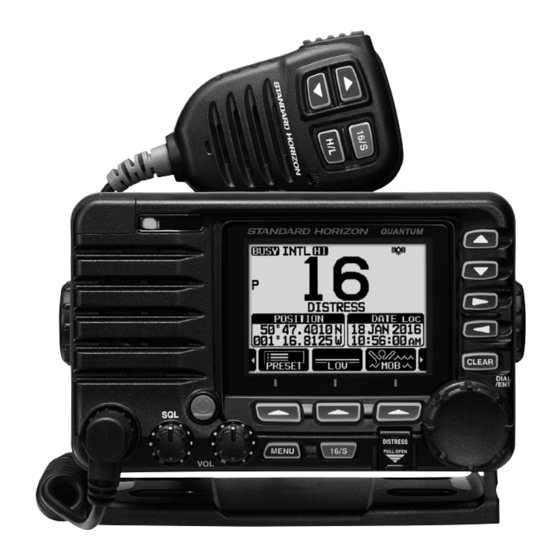
QUANTUM AIS GX6000E
25 Watt VHF/FM
Marine Transceiver
Owner's Manual
Advertisement
Table of Contents

Subscribe to Our Youtube Channel
Related Manuals for Standard Horizon QUANTUM AIS GX6000E


Summary of Contents for Standard Horizon QUANTUM AIS GX6000E
- Page 1 QUANTUM AIS GX6000E 25 Watt VHF/FM Marine Transceiver Owner’s Manual z Capable of connecting two optional wired RAM4 or one wired RAM4 and up to four Wireless RAM4W remote access microphones using SCU-30 wireless access point z Integrated NMEA 2000 interface supporting all PGNs for Navigation, GPS, AIS and DSC functions...
-
Page 2: Table Of Contents
TABLE OF CONTENTS Quick Reference Guide ........2 CHECKING GPS STATUS ......... 50 1 GENERAL INFORMATION ......3 GPS LOGGER OPERATION ........51 10 DIGITAL SELECTIVE CALLING (DSC) ..52 2 PACKING LIST ..........4 3 OPTIONAL ACCESSORIES ......4 10.1 GENERAL .............. - Page 3 TABLE OF CONTENTS 16.7 PRIORITY CHANNEL ..........117 25.1 GENERAL ..............148 16.8 SUB CHANNEL ............117 25.2 TRANSMITTER ............148 16.9 CHANNEL NAME ............. 117 25.3 RECEIVER (for Voice and DSC) ......148 16.10 NOISE CANCELLATION .......... 118 25.4 RECEIVER (for AIS) ..........149 16.11 AUDIO FILTER OPERATION ........
-
Page 4: Quick Reference Guide
Quick Reference Guide The GX6000E is equipped with the E2O (Easy-To-Operate) menu system. Basic operation may be accomplished by following the procedure below: Press and hold the key to turn on or off the radio. The MODE/STATUS indicator indicates the status of the transceiver. ... -
Page 5: General Information
1 GENERAL INFORMATION The STANDARD HORIZON GX6000E Marine VHF/FM Marine transceiver is designed to be used in International, USA, and Canadian Marine bands. The GX6000E can be operated from 11 to 16 VDC and has a switchable RF output power of 1 watt or 25 watts. -
Page 6: Packing List
2 PACKING LIST When the package containing the transceiver is first opened, please check it for the following contents: Transceiver GX6000E Speaker Microphone DC Power Cord Mounting Bracket and Hardware External GPS Antenna with 15 m of Cable SCU-31* ... -
Page 7: Safety Precautions (Be Sure To Read)
4 Safety Precautions (Be Sure to Read) Be sure to read these important precautions, and use this product safely. Yaesu is not liable for any failures or problems caused by the use or misuse of this product by the purchaser or any third party. Also, Yaesu is not liable for damages caused through the use of this product by the purchaser or any third party, except in cases where ordered to pay damages under the laws. - Page 8 WARNING When smoke or strange odors are emitted Do not bend, twist, pull, heat and modify the from the radio, turn off the power and discon- power cord and connection cables in an un- nect the power cord from the socket. reasonable manner.
-
Page 9: Getting Started
5 GETTING STARTED ABOUT VHF RADIO The radio frequencies used in the VHF marine band lie between 156 and 158 MHz with some shore stations available between 161 and 163 MHz. The marine VHF band provides communications over distances that are essentially “line of sight”... -
Page 10: Coaxial Cable
COAXIAL CABLE VHF antennas are connected to the transceiver by means of a coaxial cable – a shielded transmission line. Coaxial cable is specified by its diameter and construction. For runs less than 6 m, RG-58/U, about 6 mm in diameter is a good choice. For runs over 6 m but less than 15 m, the larger RG-8X or RG-213/U should be used for cable runs over 15 m RG-8X should be used. -
Page 11: Calling Another Vessel (Channel 16 Or 9)
8. Give your vessel’s description: length, design (power or sail), color and other distinguishing marks. The total transmission should not exceed 1 minute. 9. End the message by saying “OVER”. Release the microphone switch and listen. 10. If there is no answer, repeat the above procedure. If there is still no response, try another channel. -
Page 12: Making Telephone Calls
After a transmission, say “over,” and release the microphone’s push-to-talk (PTT) switch. When all communication with the other vessel is completed, end the last transmission by stating your Call Sign and the word “out.” Note that it is not necessary to state your Call Sign with each transmission, only at the beginning and end of the contact. -
Page 13: What Is The Range For Ais Receivers
West Coast Sea Tow Newport/LA - Ch. 27 Sea Tow San Diego - Ch. 27 Northeast Sea Tow Portland-Midcoast (Maine) - Ch. 27 Sea Tow Boston - Ch. 27 Sea Tow South Shore (Mass.) - Ch. 28 Sea Tow Rhode Island - Ch. 24 Sea Tow Eastern Long Island - Ch. -
Page 14: Controls And Indicators
6 CONTROLS AND INDICATORS This section defines each control of the transceiver. See illustration below for location of controls. For detailed operating instructions refer to chapter 7 of this manual. FRONT PANEL ... - Page 15 MENU key Press to access MENU. For details, refer to section “8.4 BASIC OPERA- TION OF THE MENU MODE”. 16/S key Pressing this key immediately recalls channel 16 from any channel loca- tion. Holding down this key selects the SUB channel (The default setting is channel 9).
-
Page 16: Microphone
MODE/STATUS indicator Indicates the radio status with the four colors on the three positions of the mode/status indicator. Position Color Description Blue AIS-Board Working Purple Receiving MSG23 Left AIS-Board Failed Green AIS Receiving (registered MMSI) Orange AIS Receiving (unregistered MMSI) Right Receive Error DATA jack... - Page 17 When an optional RAM4 and RAM4W mic is connected and intercom mode is selected, pressing the PTT switch enables voice communications from the GX6000E to the RAM4 and RAM4W second station microphone. Microphone speaker Audio heard through internal radio speaker is heard through the speaker microphone.
-
Page 18: Rear Panel
50 ohms. PA Speaker Connection Cable (Orange, Yellow, Green & Blue) Connects the GX6000E to PA speakers. See section “3 OPTIONAL ACCES- SORIES” for a list of optional STANDARD HORIZON Speakers. Green: PA1 Speaker (+) Blue: PA1 Speaker (−) Orange: PA2 Speaker (+) Yellow: PA2 Speaker (−) - Page 19 RAM-1/RAM-2 Remote Access Microphone Connectors Connects the GX6000E to the SSM-70H (RAM4) Remote Station Micro- phone or SCU-30 Wireless Access Point for use with up to four SSM-71H (RAM4W) wireless microphones. Refer to section “20 SSM-70H (RAM4) REMOTE MIC OPERATION” for details. (* The SCU-30 Wireless Access Point may be connected only to the RAM-1 connector.) ...
-
Page 20: Installation
7 INSTALLATION SAFETY / WARNING INFORMATION This radio is restricted to occupational use, work related operations only where the radio operator must have the knowledge to control the exposure conditions of its passengers and bystanders by maintaining the minimum separation distance of 1 m. - Page 21 Desktop Mounting Overhead Mounting 7.3.2 Optional MMB-84 Flush Mount Bracket 1. Use the template (page 153) to mark the location where the rectangular hole is to be cut. Confirm the space behind the dash or panel is deep enough to accommodate the transceiver (at least 17 cm deep). There should be at least 1.3 cm between the transceivers heatsink and any wiring, cables or structures.
-
Page 22: Electrical Connections
ELECTRICAL CONNECTIONS CAUTION Reverse polarity battery connections will damage the radio! Connect the power cord and antenna to the radio. Antenna and Power Supply connections are as follows: 1. Mount the antenna at least 1 m away from the radio. At the rear of the radio, connect the antenna cable. - Page 23 Ferrite Cores To suppress RF interference that can cause abnormal operation of the transceiv- er, attach the supplied two ferrite cores as shown in the next page: bigger one to the accessory connection cable and the DC input cable together, and smaller one to the PA speaker connection cable and the external speaker connection cable together.
-
Page 24: Connection Of External Devices
CONNECTION OF EXTERNAL DEVICES TO THE RADIO 7.5.1 Connecting the SCU-31 External GPS Antenna to the Radio Connect the SCU-31 cable to the GPS ANT (six pin) connector (White) on the rear panel, then tighten the cable nut (see illustration at the right). 7.5.2 Connecting the NMEA 0183/NMEA 0183-HS to the Radio External GPS Connections (NMEA 0183 4800 baud or NMEA 0183-HS... - Page 25 7.5.3 Accessory Cables and NMEA 0183 Cables The image and table below show the wires of the GX6000E and the connec- tions to optional devices such as an external GPS antenna, GPS chart plotter and an AIS receiver. CAUTION Care must be taken not to touch any of the NMEA wires to positive 12 VDC or the radio may be damaged.
- Page 26 7.5.5 Connection to External GPS or Chart Plotter 4800 / 38400 Baud Connections Radio Wires Plotter Connection GPS Receiver Blue: NMEA IN ( + ) NMEA OUT ( + ) Green: NMEA IN ( − ) NMEA OUT ( − ) Gray: NMEA OUT ( + ) NMEA IN ( + ) Brown: NMEA OUT ( −...
- Page 27 Shield of cable is not PA Speaker attached on PA Speaker end Green/Orange 2 conductor shielded Blue/Yellow Connect the shielded to GND Terminal of the GX6000 rear panel. 7.5.7 Rear Microphone Installation The GX6000E has an additional microphone connector on the rear panel that provides the same function as that on the front panel.
- Page 28 Optional SSM-70H (RAM4) Installation The GX6000E is capable of using two SSM-70H (RAM4) Remote Station Microphones to remotely control the Radio, AIS, DSC and PA/Fog functions. In addition the GX6000E can operate as a full function intercom system between the SSM-70H (RAM4) and the GX6000E. WARNING Do not connect or remove the SSM-70H (RAM4) microphone while the radio is powered on.
- Page 29 4. Finally, wind some plastic tape around each ferrite core, to prevent vibration from causing the two halves to split apart. 5. Referring to illustration right, make a 30 mm hole in the wall, then insert the extension cable into External Speaker Connections this hole.
-
Page 30: Initial Setup Required When Turning
4. Rotate the DIAL/ENT knob to select “SPEAKER SELECT”, then press the [SELECT] soft key. 5. Rotate the DIAL/ENT knob to select “INTERNAL” or “EXTERNAL”, then press the [SELECT] soft key. 6. Press the CLEAR/ key to return to radio operation. INITIAL SETUP REQUIRED WHEN TURNING ON THE POWER FOR THE FIRST TIME 7.6.1... - Page 31 3. Press the [MMSI] soft key. The [MMSI] soft key is displayed which has not yet ********* set the MMSI. In the case of the GX6000E which has completed the MMSI setting, you can only check the MMSI on this screen. 4.
-
Page 32: Checking Gps Signal (Gps Status Display)
CHECKING GPS SIGNAL (GPS STATUS DISPLAY) When the GX6000E receives the GPS signal from the SCU-31, a small satel- lite icon “ ” will appear on the display and your current location (latitude/ longitude) is shown on the display. (*When the GPS signal receiving from the NMEA 2000 or NEMA-0183, a “2K”... -
Page 33: Gps Configuration
GPS CONFIGURATION 7.8.1 Changing the GPS Time The GX6000E shows GPS satellite time or UTC (Universal Time Coordinated) time in factory default. A time offset is needed to show the local time in your area. The time offset must be changed in order for the radio to display the current time in your area. - Page 34 4. Rotate the DIAL/ENT knob to select “TIME AREA”, then press the [SELECT] soft key. 5. Rotate the DIAL/ENT knob to select “UTC” or “LOCAL”. 6. Press the [ENTER] soft key to store the selected setting. 7. Press the CLEAR key to return to radio operation. 7.8.3 Changing the Time Format This menu selection allows the radio to setup to show time in 12-hour or...
- Page 35 7.8.4 Changing COG to True or Magnetic Allows the GPS COG (Course Over Ground) and the BRG from an AIS target to be selected to show in ON or OFF. Factory default is “OFF” however by following the steps below the COG can be changed to “ON”. 1.
-
Page 36: Basic Operation
8 BASIC OPERATION TURNING ON AND OFF THE TRANSCEIVER 1. After the transceiver has been installed, ensure that the power supply and antenna are properly connected. 2. Press and hold the key to turn the radio on. 3. Press and hold the key again to turn the radio off. -
Page 37: Basic Operation Of The Menu Mode
8.3.1 Transmit Power The TX output power of the GX6000E is set to high level (25 W) in factory default, and the “[HI]” indicator is displayed on the top part of the screen. To switch the TX output power: 1. Press the ►/◄ key repeatedly until the [HI] or [LOW] soft key is displayed at the bottom of the screen. -
Page 38: Transmit Time-Out Timer (Tot)
5. Rotate the DIAL/ENT knob or press the ▲/▼ key to select the desired setting. 6. Press the [ENTER] soft key to or press the DIAL/ENT knob store the selected setting. 7. Press the CLEAR key to return to radio operation. (The display can also be returned to the previous screen by pressing the [BACK] soft key.) The same operation process as the above is written as follows in this opera-... -
Page 39: International, Usa, And Canada Mode
INTERNATIONAL, USA, AND CANADA MODE To change the channel group from International to USA or Canada: 1. Press the MENU key to display “MENU”. 2. Rotate the DIAL/ENT knob to select “SETUP”, then press the [SELECT] soft key. 3. Rotate the DIAL/ENT knob to select “CHANNEL SETUP”, then press the [SELECT] soft key. - Page 40 8.8.1 NOAA Weather Alert In the event of extreme weather disturbances, such as storms and hurricanes, the NOAA (National Oceanic and Atmospheric Administration) sends a weather alert accompanied by a 1050 Hz tone and subsequent weather report on one of the NOAA weather channels. The GX6000E can receive weather alerts when monitoring a weather channel and, on the last selected weather channel during scanning modes or while on another working channel.
-
Page 41: Multi Watch (To Priority Channel)
MULTI WATCH (TO PRIORITY CHANNEL) Multi watch is used to scan two or three channels for communications. • In Dual Watch, a normal VHF channel and the priority channel are scanned alternately. • In Triple Watch, a normal VHF channel, the priority channel, and the sub channel are scanned alternately. -
Page 42: Scanning
NOTE The priority channel may be changed from CH16 (default) to another channel. Refer to section “16.7 PRIORITY CHANNEL”. 8.10 SCANNING The GX6000E will automatically scan channels programmed into the preset channel memory and also the scan channel memory, and the last selected weather channel. - Page 43 4. To REMOVE a channel from the list, select the channel then press the [MEM] soft key. “ON” icon of the selected channel will disappear. 5. When you have completed your selection, press the CLEAR key to return to radio operation. To check channels to be scanned, rotate the DIAL/ENT knob.
-
Page 44: Preset Channels: Instant Access
NOTE In the default setting, Channel 16 is set as the priority channel. You may change the priority channel to the desired channel from Channel 16 on the SETUP menu. Refer to section “16.7 PRIORITY CHANNEL”. 8.11 PRESET CHANNELS: INSTANT ACCESS 10 preset channels can be programmed for instant access. -
Page 45: Mob Operation
8.11.2 Operation 1. Press the ►/◄ key repeatedly, then press the [PRESET] soft key to recall the preset channel. The “[P-SET]” icon will appear on the display. 2. Rotate the DIAL/ENT knob to select the desired preset channel. 3. Press the [PRESET] soft key to return to the last selected channel. -
Page 46: Pa/Fog Operation
The GX6000E has two 25 W hailers built-in and can be used with any 4 Ohm PA horn. Standard Horizon offers two HAIL/PA horns, the 220SW (12 cm round 30 Watt HAIL/PA horn) and the 240SW (13 x 20 cm rectangular 40 Watt HAIL/ PA horn). - Page 47 2. Rotate the DIAL/ENT knob to speaker select “ALL”, “PA1” or “PA2”, then press the [SELECT] soft key. Press the microphone’s PTT switch to speak through the HAIL/PA speaker. 3. Press the [PA VOL] soft key, then rotate the DIAL/ ENT knob to control the AF output level.
- Page 48 8.13.3 Fog Signal Timing Chart TYPE PATTERN USAGE UNDERWAY One 5-second blasts Motor vessel underway and every 120 seconds. making way. Listen Back 120s STOP Two 5-second blasts Motor vessel underway but ( s e p a r a t e d b y 2 stopped (not making way).
-
Page 49: Intercom Operation
3. Rotate the DIAL/ENT knob to speaker select “ALL”, “PA1” or “PA2”, then press the [SELECT] soft key. 4. On the “Horn” and “Siren” modes, while pressing the [HORN] soft key to activate the tone through the HAIL/PA speaker. Press the [FOG VOL] soft key, then rotate the DIAL/ ENT knob to control the AF output level. -
Page 50: Voice Scrambler
8.16 DEMO MODE This mode is used by Standard Horizon sales persons and dealers to demonstrate radio, DSC and AIS functions. Demo mode allows latitude, longitude and time to be entered to simulate radio displays. When the demo mode is enabled, the radio display will automatically switch from the NORMAL, COMPASS, WAYPOINT, AIS and GM displays. - Page 51 4. To store the data entered, press the [FINISH] soft key. 5. Rotate the DIAL/ENT knob to select “DEMO START”, then press the [SELECT] soft key. 6. Rotate the DIAL/ENT knob to select “START”, then press the [SELECT] soft key. NOTE To stop the demo mode, select “STOP”...
-
Page 52: Gps Operation
9 GPS OPERATION The GX6000E has the SCU-31 external GPS antenna to receive and display the position information. When the radio is connected to an external GPS device by the NMEA-0183 or NMEA2000, you may select the order of priority of the connection devices to be used when obtaining location information via the SETUP menu (Refer to section “18.1 ORDER OF PRIORITY”). -
Page 53: Gps Logger Operation
GPS LOGGER OPERATION The GX6000E includes a logger for position information that allows you to record your location at regular intervals. (Requires SCU-31 external GPS antenna.) 1. Press the [LOGGER] soft key to turn the function on or off. The recording starts and the display returns to the previous screen with the “... -
Page 54: Digital Selective Calling (Dsc)
10 DIGITAL SELECTIVE CALLING (DSC) 10.1 GENERAL WARNING This GX6000E is designed to generate a digital maritime distress and safety call to facilitate search and rescue. To be effective as a safety device, this equipment must be used only within communication range of a shore-based VHF marine channel 70 distress and safety watch system. -
Page 55: Dsc Distress Alert
10.2 DSC DISTRESS ALERT The GX6000E is capable of transmitting and receiving DSC distress messages to all DSC radios. Distress alert calls from the GX6000E include the latitude and longitude of the vessel when the external GPS unit is activated. 10.2.1 Transmitting a DSC Distress Alert NOTE... - Page 56 Transmitting a DSC Distress Alert with Nature of Distress The GX6000E is capable of transmitting a DSC distress alert with the following “Nature of Distress” categories: Undesignated, Fire/Explosion, Flooding, Collision, Grounding, Capsizing, Sinking, Adrift, Abandoning, Piracy, MOB. ] “DSC CALL” “DIST ALERT MSG” 2.
- Page 57 Pausing a DSC Distress Alert After a DSC distress call is transmitted, the DSC distress call is repeated every 4 minutes until the call is canceled by the user or until the radio is turned off and on again. The GX6000E has the capability to suspend (pause) the retransmit- ting of the distress call by the procedure below.
- Page 58 10.2.2 Receiving a DSC Distress Alert 1. When a DSC distress call is received, an emergency alarm sounds. 2. Press any key to stop the alarm. 3. Rotate the DIAL/ENT knob to show information on the vessel in distress. On the display you will notice 3 soft key selections. These selections are described below: [ACCEPT]: Press this key to accept the DSC distress call and to switch to Channel 16.
-
Page 59: All Ships Call
10.3 ALL SHIPS CALL The all ships call function allows contact to be established with DSC equipped vessels without having their MMSI in the individual calling directory. Also, priority for the call can be designated as “Safety” or “Urgency”. SAFETY Call: This type of call is used to transmit boating safety information to other vessels. - Page 60 7. Press the [QUIT] soft key to exit the all ships call menu. 10.3.2 Receiving an All Ships Call 1. When an all ships call is received, an emergency alarm will sound. The display shows the MMSI of the vessel transmit- ting the all ships call and the radio will change to the requested channel after 30 seconds (the default setting of “AUTO CHANNEL CHANGE”).
-
Page 61: Individual Call
10.4 INDIVIDUAL CALL This feature allows the GX6000E to contact another vessel with a DSC VHF radio and automatically switch the receiving radio to a desired communications channel. This feature is similar to calling a vessel on CH16 and requesting to go to another channel (switching to the channel is private between the two vessels). - Page 62 8. Rotate the DIAL/ENT knob to select “MMSI:”, then press the [SELECT] soft key. 9. Rotate the DIAL/ENT knob to scroll through numbers, 0-9. To enter the desired number and move one space to the right by pressing the [SELECT] soft key.
- Page 63 10.4.4 Transmitting an Individual Call This feature allows the user to contact another vessel with a DSC radio. This feature is similar to calling a vessel on CH16 and requesting to go to another channel. Individual Call using the Individual/Position Directory ] ...
- Page 64 Individual Call by Manually Entering an MMSI You may enter an MMSI number manually to contact without storing it in the individual directory. ] “DSC CALL” “INDIVIDUAL CALL” 2. Rotate the DIAL/ENT knob to select “MANUAL”, then press the [SELECT] soft key. 3.
- Page 65 10.4.5 Receiving an Individual Call When an individual DSC call is received, the radio will automatically respond (default setting) to the calling ship, and switch to the requested channel for voice communications. Refer to section “10.4.2 Setting up the Individual Call Reply”...
- Page 66 4. After accepting the call, press the [ABLE] soft key to switch to the requested channel. (To inform the vessel that you are unable to respond, press the [UNABLE] soft key.) 5. Press the [YES] soft key to send an acknowledge- ment.
-
Page 67: Group Call
MMSI numbers. The first digit of a group MMSI is always set to “0” by International rules. All Standard Horizon radios are preset so when programming a group MMSI the first digit is set to “0”. - Page 68 Second, Third and Fourth digits of the group MMSI as it denotes the area the ship is located in. The last 5 digits are decided upon by persons in the group. This is an impor- tant step as all radios in the group must contain the same group MMSI so they can be contacted by each other.
- Page 69 If a mistake was made entering in the MMSI number, rotate the DIAL/ENT knob to select “←” or “→”, press the [SELECT] soft key until the wrong character is selected, then perform step 9. 10. When finished entering the MMSI number, press the [FINISH] soft key to confirm. 11.
- Page 70 Group Call by Manually Entering an MMSI This feature allows you to contact a group of vessels by entering in their group MMSI manually. ] “DSC CALL” “GROUP CALL” 2. Rotate the DIAL/ENT knob to select “MANUAL”, then press the [SELECT] soft key.
- Page 71 10.5.3 Receiving a Group Call 1. When a group call is received, the GX6000E will produce a ringing alarm sound. 2. The display shows the group MMSI number. 3. Press any key to stop the alarm. On the display you will notice 3 soft key selections. These selections are described below: [ACCEPT]: Press this key to accept the group call and to switch to requested channel.
-
Page 72: Position Request
GX6000E. Standard Horizon has taken this feature one step further, if a compatible GPS chart plotter is connected to the GX6000E, the polled position of the vessel is shown on the display of the GPS chart plotter making it easy to navigate to the location of the polled vessel. - Page 73 3. Press the [ENTER] soft key to store the selected setting. 4. Press the CLEAR key to return to radio operation. 10.6.2 Transmitting a Position Request to Another Vessel Position Request using the Individual/Position Directory Refer to section “10.4 INDIVIDUAL CALL” to enter information into the indi- vidual directory.
- Page 74 2. Rotate the DIAL/ENT knob to select “MANUAL”, then press the [SELECT] soft key. 3. Rotate the DIAL/ENT knob to select the first number of the MMSI (nine digits) which you want to contact, then press the [SELECT] soft key to step to the next number.
- Page 75 4. Press the [QUIT] soft key to return to the channel display. NOTE When there is an unread position request call, “ ” icon will appear on the display. You may review the unread individual call from the DSC log, refer to the section “10.11.3 Reviewing Other Logged Calls”. 10.6.4 Manual Input of Position Information If the GX6000E is located in an area where GPS reception is limited when you...
-
Page 76: Position Report
10.6.5 Setting up a Position Request Ringer The GX6000E has the capability to turn off the position request ringer. ] “SETUP” “DSC SETUP” “DSC BEEP” 2. Rotate the DIAL/ENT knob to select “POS REQUEST”, then press the [SELECT] soft key. 3. - Page 77 4. If you want to change the position displayed, press the [POS/TM] soft key to go to the position information input screen. After inputting new position information, press the [FINISH] soft key to confirm. 5. Press the [YES] soft key to send your position to the selected vessel. 6.
- Page 78 8. Press the [QUIT] soft key to return to radio operation. 10.7.2 Receiving a DSC Position Report Call When another vessel transmits their vessels location to the GX6000E the following will happen: 1. When a position report call is received from another vessel, a ringing sound will be produced.
- Page 79 3. The display indicates the distance and direction of the received vessel, and the compass displays the received vessel with a dot (). Stopping Navigation to the Reported Position 1. Press one of the soft keys to show the key selections. 2.
-
Page 80: Polling Call
Navigating to a Saved Waypoint Refer to section “11.1.1 Starting and Stopping Navigation” for details. 10.7.5 Setting up a Position Report Ringer The GX6000E has the capability to turn off the position report ringer. ] “SETUP” “DSC SETUP” “DSC BEEP” 2. - Page 81 4. Press the [YES] soft key to transmit the polling call. 5. After a polling call is transmitted, if the reply signal is not received, “Waiting for ACK” is shown on the display which means the GX6000E is waiting for the vessel you called to send an acknowledgement.
-
Page 82: Auto Position Polling
10.8.2 Receiving a Polling Call When another vessel transmits a polling call to the GX6000E the following will happen: 1. When a polling call is received, the radio will automati- cally respond to the calling vessel. 2. To exit from the polling call display, press the [QUIT] soft key. - Page 83 10.9.3 Selecting Vessels to be Automatically Polled NOTE The radio uses the individual directory to select vessels to be auto- matically polled. Refer to section “10.4.1 Setting up the Individual / Position Call Directory” and to enter MMSI of vessels you want to poll before proceeding.
-
Page 84: Dsc Test
4. Press the CLEAR key to return to radio operation. 5. Auto POS Polling starts and “[A]” icon will light up on the screen. 10.10 DSC TEST This function is used to contact another DSC equipped vessel to ensure the DSC functions of the radio are operating. - Page 85 DSC Test Call by Manually Entering an MMSI ] “DSC CALL” “DSC TEST CALL” “MANUAL” 2. Rotate the DIAL/ENT knob to select “MANUAL”, then press the [SELECT] soft key. 3. Rotate the DIAL/ENT knob to select the first digit in the MMSI, then press the [SELECT] soft key.
-
Page 86: Dsc Log Operation
10.11 DSC LOG OPERATION The GX6000E logs transmitted calls, received DSC distress calls, and other calls (individual, group, all ships, etc.). The DSC log feature is similar to an answer machine where calls are recorded for review and a “ ”... - Page 87 10.11.2 Reviewing a Logged DSC RX Distress Call The GX6000E allows logged DSC RX distress call to be reviewed. ] “DSC CALL” “DSC LOG” “RX DISTRESS” 2. Rotate the DIAL/ENT knob to select the station (name or MMSI number) you want to review and/or relay the distress call to other vessels.
-
Page 88: Dsc Loop Back Operation
10.11.4 Deleting Logged Calls from the DSC Log Directory ] “DSC CALL” “DSC LOG” “LOG DELETE” 2. Rotate the DIAL/ENT knob to select the category (“TRANSMITTED”, “RX DISTRESS”, “RX OTHER CALL” or “ALL LOG”) to be deleted. 3. -
Page 89: Navigation
11 NAVIGATION The GX6000E is capable of storing up to 250 waypoints for navigation using the compass page. You can also navigate to DSC distress calls with position or a position received from another DSC radio using DSC polling. 11.1 WAYPOINT OPERATION 11.1.1 Starting and Stopping Navigation... - Page 90 4. Rotate the DIAL/ENT knob to select “POSITION:”, then press the [SELECT] soft key. 5. Rotate the DIAL/ENT knob to select the first number of latitude, then press the [SELECT] soft key to step to the next number. 6. Repeat step 5 to set the position. If a mistake was made, rotate the DIAL/ENT knob to select “←”...
- Page 91 4. If you want to modify the position, rotate the DIAL/ENT knob to select “POSITION:”, press the [SELECT] soft key, then enter the new coordinates. When finished modifying the position, press the [FINISH] soft key. 5. Rotate the DIAL/ENT knob to select “SAVE”, then press the [SELECT] soft key to save the mark posi- tion into memory.
- Page 92 3. Rotate the DIAL/ENT knob to select the waypoint to be edited, then press the [SELECT] soft key to show the waypoint input display. 4. Rotate the DIAL/ENT knob to select “NAME:” or “POSITION:”, then press the [SELECT] soft key. 5.
-
Page 93: Routing Operation
11.1.3 Selecting the Display Range This menu item allows setting of the range on the compass display. ] “SETUP” “WAYPOINT SETUP” “DISPLAY RANGE” 2. Rotate the DIAL/ENT knob to select desired range. (Unit of measure depends on the settings in the GPS SETUP menu. - Page 94 Adding a Route ] “SETUP” “WAYPOINT SETUP” “ROUTE DIRECTORY” 2. Rotate the DIAL/ENT knob to select “ADD”, then press the [SELECT] soft key. 3. Rotate the DIAL/ENT knob to select “NAME:”, then press the [SELECT] soft key. 4.
- Page 95 2. Rotate the DIAL/ENT knob to select “EDIT”, then press the [SELECT] soft key. 3. Rotate the DIAL/ENT knob to select the route to be edited, then press the [SELECT] soft key to show the route input display. 4. Perform steps 3 to 11 of the previous page until the route is updated.
- Page 96 3. Rotate the DIAL/ENT knob to select a route, then press the [SELECT] soft key. The navigation screen with “RUT” indicator appears. 4. A message “ARRIVED” will appear when you have reached to the first target point. To start navigation to the next target, press the [YES] soft key.
-
Page 97: Gm Operation
12 GM OPERATION The GM (Group Monitor) feature of the GX6000E utilizes the same system as the DSC Group call and Auto Position Polling, to display the group members' locations. 12.1 SETTING UP GM OPERATION The GX6000E is capable of storing up to 10 groups with 1 to 9 members each. 12.1.1 Setting Up GM Group Directory NOTE... - Page 98 7. Rotate the DIAL/ENT knob to select a list number, then press the [SELECT] soft key. 8. Rotate the DIAL/ENT knob to select a member from the Individual directory, then press the [SELECT] soft key. 9. Repeat steps 8 to add members to the group, then press the [BACK] soft key.
-
Page 99: Starting Gm Operation
12.2 STARTING GM OPERATION NOTE To start GM operation, configure the GM Group Directory setting in setup menu. Otherwise, you cannot start the GM operation. Refer to section “12.1.1 Setting Up GM Group Directory” for details. ] “GM” 2. Rotate the DIAL/ENT knob to select the desired category (“HISTORY”... - Page 100 The GM group being monitored changes. The GM target display appears. 5. Press the CLEAR key to return to radio operation. 12.2.2 Transmitting a DSC Call to a Group Member 1. On the GM target display, press one of the soft keys to show the key selections.
-
Page 101: Automatic Identification System (Ais)
13 AUTOMATIC IDENTIFICATION SYSTEM (AIS) 13.1 GENERAL NOTE • The GX6000E is equipped with an antenna connection designated for AIS. By connecting a marine antenna to this connector, the transceiver can receive AIS signals while receiving a VHF voice transmissions. •... -
Page 102: Ais Operation
13.2 AIS OPERATION The GX6000E is equipped with an AIS receiver and can display AIS targets around your vessel on the radio's display. Therefore, you can identify and avoid in proximity to your vessel. NOTE To show AIS targets on the radio’s display, the SCU-31 or an external GPS devices needs to be connected via NMEA 0183 or NMEA 2000 so the radio knows its position relative to the AIS targets. - Page 103 3. Rotate the DIAL/ENT knob to select the MMSI number (or vessel name). then press the [SELECT] soft key. Pressing the [DANGER] soft key changes the order to the TCPA time order. 4. The AIS target information screen appears. To see more information of the AIS target, press the [NEXT] soft key.
- Page 104 4. Press the [CALL] soft key 5. In the INTERSHIP CH list, rotate the DIAL/ENT knob to select the operating channel on which you want to communicate, then press the [SELECT] soft key. To select operating channels from all voice channels, press the [MANUAL] soft key.
-
Page 105: Ais Setup
3. On the display you will notice 3 soft key selections. These selections are described below: [INFO]: Pressing this key shows the information screen of the CPA/TCPA alarm targets. [CALL]: Pressing this key switches the screen to the setting screen for transmitting individual DSC calls. - Page 106 ] “SETUP” “AIS SETUP” “TCPA” 2. Rotate the DIAL/ENT knob to select the time you want the radio to alert you of an approaching AIS equipped vessel. The time can be set from “1min” to “30min” (“10min” is default). 3.
- Page 107 2. Rotate the DIAL/ENT knob to select “IGNORE VESSELS”, then press the [SELECT] soft key. 3. Rotate the DIAL/ENT knob to select “ADD”, then press the [SELECT] soft key. 4. Press the [SELECT] soft key. 5. Rotate the DIAL/ENT knob to scroll through numbers, 0-9.
-
Page 108: Nmea 2000 Setup
14 NMEA 2000 SETUP Set the device numbers and system numbers of devices connected to the NMEA 2000 network. 14.1 SELECT DEVICE Select the device for which you want to set the device number and system number. ] “SETUP” “NMEA2000 SETUP” “SELECT DEVICE” 2. -
Page 109: System Number
14.3 SYSTEM NUMBER Set the system number of the device selected in “14.1 SELECT DEVICE”. ] “SETUP” “NMEA2000 SETUP” “SYSTEM NUMBER” 2. Rotate the DIAL/ENT knob to select the first digit of the system number, then press the [SELECT] soft key to step to the next number. - Page 110 Receive Transmit 129029 GNSS Position Data 129029 GNSS Position Data 129033 Local Time Offset − − − − 129038 AIS Class A Position Report − − 129039 AIS Class B Position Report 129040 AIS Class B Extended Position − − Report 129041 AIS Aids to Navigation (AtoN)
-
Page 111: Configuration Setup
15 CONFIGURATION SETUP 15.1 DISPLAY MODE The display mode can be selected according to the time of day you operate the radio. ] “SETUP” “CONFIGURATION” “DISPLAY MODE” 2. Rotate the DIAL/ENT knob to select the desired setting. You can select one from “DAY MODE” or “NIGHT MODE”. -
Page 112: Key Beep
15.4 KEY BEEP This selection is used to select the beep tone volume level when a key is pressed. ] “SETUP” “CONFIGURATION” “KEY BEEP” 2. Rotate the DIAL/ENT knob to select the desired level. The beep level can be set from “1” to “7”, or “OFF” (“4”... -
Page 113: Station Name
2. Rotate the DIAL/ENT knob to select “OFF” or “ON” (“ON” is default). 3. Press the [ENTER] soft key to store the selected setting. 4. Press the CLEAR key to return to radio operation. 15.7 STATION NAME This function allows you to change the name of the radio or second station microphone. -
Page 114: Soft Keys
10. Repeat steps 8 and 9 until the name is complete. The name can consist of up to ten characters, and if you do not use all ten characters, select “→” to move to the next space. This method can also be used to enter a blank space in the name. - Page 115 SOFT KEY NUMBERS DISPLAY FUNCTION ASSIGNED AS DEFAULT (See the previous page.) NONE − − TX HI/LO Selects transmit power WX/CH Switches channels between weather and marine SCAN Turns on or off scanning function DUAL WATCH Starts and stops dual watch scan MARK POSITION Marks the current position for a “Waypoint”...
-
Page 116: Mode/Status Led Dimmer
15.9 MODE/STATUS LED DIMMER This menu selection adjusts the MODE/STATUS indicator intensity. ] “SETUP” “CONFIGURATION” “MODE/STATUS LED DIMMER” 2. Rotate the DIAL/ENT knob to select the desired level (“7” is default). When “OFF” is selected, the indicator does not light. -
Page 117: Summary Of The Configuration Setup
15.11 SUMMARY OF THE CONFIGURATION SETUP Item Description Default Value Page DISPLAY MODE Toggles LCD display mode between DAY MODE daytime and nighttime mode DIMMER Adjusts the backlight level of the DAY MODE: 7 LCD and keypad NIGHT MODE: 4 CONTRAST Adjusts the contrast of the LCD KEY BEEP... -
Page 118: Channel Function Setup
16 CHANNEL FUNCTION SETUP 16.1 CHANNEL GROUP This menu item allows you to select a channel group from USA, Canada, and International. Refer to section “8.7 INTERNATIONAL, USA, AND CANADA MODE” for details. 16.2 WEATHER ALERT Enables/disables the NOAA Weather Alert function. The default setting is “ON”. ] ... -
Page 119: Multi Watch
16.6 MULTI WATCH This selection is used to select the watch type between “DUAL” and “TRIPLE”. The default setting is “DUAL”. Refer to section “8.9 MULTI WATCH (TO PRIORITY CHANNEL)” for details. 16.7 PRIORITY CHANNEL This procedure allows the radio to use a different priority channel used when priority scanning. -
Page 120: Noise Cancellation
4. Press the [SELECT] soft key to store the first letter in the name and step to the next letter to the right. 5. Repeat step 3 and 4 until the name is complete. The name can consist of up to 16 characters, if you do not use all 16 characters, select “→”... -
Page 121: Audio Filter Operation
4. Rotate the DIAL/ENT knob to select “RX MODE”, then press the [SELECT] soft key. 5. Rotate the DIAL/ENT knob to select the noise level from “LEVEL1” through “LEVEL4” or “OFF”, then press the [ENTER] soft key. 6. Press the CLEAR key to return to radio operation. 16.11 AUDIO FILTER OPERATION This menu item allows you to select operation of the internal audio filter for the best acoustics in noisy environments. - Page 122 2. Rotate the DIAL/ENT knob to select “RECORDING DELAY TIME”, then press the [SELECT] soft key. 3. Rotate the DIAL/ENT knob to select the desired delay time. The delay time can be set to “1sec” through “5sec”. 4. Press the [ENTER] soft key to store the new setting. 5.
-
Page 123: Scrambler Setup
3. Press the [YES] soft key. (To cancel, press the [NO] soft key.) 4. Press the [OK] soft key. 5. Press the CLEAR key to return to radio operation. 16.13 SCRAMBLER SETUP Configure the voice scrambler setting. Two types of voice scrambler functions are available: the 4-code type (CVS2500A compatible) and the 32-code type (FVP-42 compatible for Furuno Electric FM-4721) (This function is not avail- able for CH16 and CH70). -
Page 124: Summary Of The Cannel Function Setup
6. Rotate the DIAL/ENT knob to select the scrambler code. The scrambler code can be set from “00” to “03” or “OFF” (While FVP-42 is selected in step 6, the scrambler code can be set from “00” to “31” or “OFF”). -
Page 125: Dsc Setup
17 DSC SETUP 17.1 INDIVIDUAL DIRECTORY The GX6000E has a DSC directory that allows you to store a vessel or person’s name and the associated MMSI you wish to contact via individual calls, position requests and position report transmissions. To transmit an individual call you program this directory with information of the vessel you wish to contact, similar to a cellular phone's telephone directory. -
Page 126: Position Reply
17.6 POSITION REPLY The GX6000E can be set up to automatically (default setting) or manually send your position when requested by another vessel. This selection is important if you are concerned about someone polling the position of your vessel that you may not want to. -
Page 127: Action Timer
17.10 NO ACTION TIMER If no key is pressed during the “MENU” or “DSC CALL” screen, the GX6000E will automatically return to radio operation. The default selection is 15 minutes. ] “SETUP” “DSC SETUP” “NO ACTION TIMER” 2. - Page 128 Item Description Default Value Page GROUP DIRECTORY Enter or edit addresses used for − group call POSITION REPLY Selects reply mode when receiv- AUTO ing a position call AUTO POSITION Selects the AUTO POSITION AUTO POS REQUEST POLLING POLLING operation type AUTO POS INTERVAL Selects the transmission interval 30 sec...
-
Page 129: Gps Setup
18 GPS SETUP The “GPS Setup” mode allows the parameters for the NMEA2000 or the NMEA -0183 or the SCU-31 external GPS antenna to be customized for your operat- ing requirements. 18.1 ORDER OF PRIORITY Specify the order of priority of the connection devices to be used when obtain- ing location information. -
Page 130: Time Offset
2. Rotate the DIAL/ENT knob to select the desired coor- dinate system. The location format can be selected from “ddd°mm.mmmm” and “ddd°mm’ss””. 3. Press the [ENTER] soft key to save the new setting. 4. Press the CLEAR key to return to radio operation. 18.4 TIME OFFSET Sets the local time offset between UTC (Universal Time Coordinated) and local... -
Page 131: Nmea 0183 In/Out
18.9 NMEA 0183 IN/OUT 18.9.1 Data Speed This menu is used to setup the NMEA 0183 baud rate of the GPS input (Blue and Green wires) and DSC output (Gray and Brown wires). The default setting is 4800 bps. ] “SETUP” “GPS SETUP” “NMEA 0183 IN/OUT” 2. -
Page 132: Position Data Output
NOTE • Data output will be performed based on the data acquisition order of priority configured from “ORDER OF PRIORITY”. Refer to section “18.1 ORDER OF PRIORITY” for details. • While “UNIT POWER” of “OPTION GPS UNIT” is set to OFF, NMEA sentences will not be output. - Page 133 ] “SETUP” “GPS SETUP” “OPTION GPS UNIT” 2. Rotate the DIAL/ENT knob to select “UNIT POWER”, then press the [SELECT] soft key. 3. Rotate the DIAL/ENT knob to select “OFF” or “ON”. 4. Press the [ENTER] soft key to store the new setting. 5.
- Page 134 2. Rotate the DIAL/ENT knob to select “DIFFERENTIAL GPS”, then press the [SELECT] soft key. 3. Rotate the DIAL/ENT knob to select “OFF” or “ON”. 4. Press the [ENTER] soft key to store the new setting. 5. Press the CLEAR key to return to radio operation. 18.11.4 Logger Interval ] ...
-
Page 135: Summary Of The Gps Setup
18.11.5 Log Erase ] “SETUP” “GPS SETUP” “OPTION GPS UNIT” 2. Rotate the DIAL/ENT knob to select “LOG ERASE”, then press the [SELECT] soft key. 3. Press the [YES] soft key. (To cancel, press the [NO] soft key.) 4. - Page 136 Item Description Default Value Page NMEA 0183 IN/OUT DATA SPEED Sets the NMEA 0183 data speed 4800bps OUTPUT SENTENCES Enables/disables NMEA sentences GLL: ON GGA: ON GSA: ON GSV: ON RMC: ON DSC/DSE: ON POS DATA OUTPUT Selects the connection device NMEA 2000: OFF when outputting position data NMEA-0183: OFF...
-
Page 137: Atis Setup
19 ATIS SETUP The GX6000E supports the ATIS (Automatic Transmitter Identification System) used in Inland waterways in Europe. When enabled ATIS mode transmits a unique ATIS code each time the PTT switch is released at the end of a trans- mission. -
Page 138: Atis Ch Group
19.2 ATIS CH GROUP The GX6000E has the capability to turn on and off the ATIS feature for each channel group. ] “SETUP” “ATIS SETUP” “ATIS GROUP” 2. Rotate the DIAL/ENT knob to select the channel group (International, Canadian*, or USA) you wish to change the setting, and press the [SELECT] soft key. -
Page 139: Ssm-70H ( Ram4 ) Remote Mic Operation
20 SSM-70H ( RAM4 ) REMOTE MIC OPERATION When a remote microphone is connected to the GX6000E, all VHF, DSC, setup menus, AIS, Navigation, GM (Group Monitor) functions and PA/Fog modes can be remotely operated. The SSM-70H’s operation is same as GX6000E except the receiver audio volume setting and squelch level setting. - Page 140 Secondary use Press this knob to enter a selection in the MENU. SQL key (Squelch control) Press this key to activate the squelch adjusting mode. Press the CH▲ or CH▼ key to adjust the squelch threshold level. PTT (Push-To-Talk) switch Push this switch to enable the transmitter.
-
Page 141: Ram4 Soft Key Assignment
16/S key Pressing this key immediately recalls channel 16 from any channel location. Holding down this key recalls the SUB channel (The default setting is channel 9). Pressing this key again reverts to the previous selected working channel. Speaker The internal speaker is located here. DATA jack Use the micro USB type B jack for SSM-70H (RAM4) firmware updates. - Page 142 NOTE You can assign functions to soft keys on each of the transceiver and the optional SSM-70H (RAM4) remote mic. 20.2.1 Key Assignment Configure all settings on the SSM-70H (RAM4) remote mic for which you want to assign functions to soft keys. ] ...
-
Page 143: Connecting A Usb Data Terminal
The GX6000E settings can be programmed using the USB terminal and PC Programming Software. You can also download the log data from the radio by using the PC Programming Software which may be downloaded from the Standard Horizon website. The PC Programming Software is compatible with Windows ®... -
Page 144: Maintenance
11 VDC. • Use only STANDARD HORIZON approved accessories and replacement parts. In the unlikely event of serious problems, please contact your Dealer or our repair facility. Address and phone numbers for this facility, as well as warranty information, are contained in section “24 WARRANTY”. -
Page 145: Troubleshooting Chart
22.3 TROUBLESHOOTING CHART SYMPTOM PROBABLE CAUSE REMEDY Transceiver fails to No DC voltage to the a. Check the 12VDC battery connections power up. transceiver, or blown fuse. and the fuse. b. The key needs to be pressed and held to turn the radio on. T r a n s c e i v e r Reversed power wires. -
Page 146: Channel Assignments
23 CHANNEL ASSIGNMENTS CHANNEL USE TX (MHz) RX (MHz) SIMPLEX/DUPLEX LOW PWR All countries Germany (except Germany) 156.050 160.650 DUPLEX – TELEPHONE NAUTIK 156.100 160.700 DUPLEX – TELEPHONE NAUTIK 156.150 160.750 DUPLEX – TELEPHONE NAUTIK 156.200 160.800 DUPLEX – INTL NAUTIK 156.250 160.850... - Page 147 CHANNEL USE TX (MHz) RX (MHz) SIMPLEX/DUPLEX LOW PWR All countries Germany (except Germany) 156.825 SIMPLEX – NAUTIK 156.875 SIMPLEX LOW* PORT OPR SHIP-SHIP 156.925 161.525 DUPLEX – INTL NAUTIK 1078 156.925 SIMPLEX – – – 2078 161.525 SIMPLEX – –...
-
Page 148: Warranty
Product or part(s) therein which, upon examination by STANDARD HORIZON, appear to be defective or not up to factory specifications. STANDARD HORIZON may, at its option, repair or replace parts or subassemblies with new or reconditioned parts and subassemblies. - Page 149 Products, or for the operation of the Product with any ancillary equipment and all such equipment is expressly excluded from this warranty. STANDARD HORIZON disclaims liability for range, coverage, or operation of the Product and ancillary equipment as a whole under this warranty.
-
Page 150: Specifications
25 SPECIFICATIONS Performance specifications are nominal, unless otherwise indicated, and are subject to change without notice. Measured in accordance with TIA/EIA-603. 25.1 GENERAL Channels .............All International, USA and Canadian* (*: Depending on the region setting) Normal Input Voltage ..................13.8 V DC Operating Voltage Range ................ -
Page 151: Receiver (For Ais)
Audio Response ............within +1/–3dB of a 6 dB/Octave de-emphasis characteristic at 300 to 3000 Hz Frequency Stability ............±0.0003 % (–20 °C to +60 °C) Channel Spacing ....................25 kHz DSC Format ..................ITU-R M.493-14 (Asia, Australia: Meets ITU-R M.493-13 Class D) Attenuator (Local) ..................Approx. -
Page 152: Dimensions
25.7 DIMENSIONS 6.2" ( 155.4 mm ) 6" ( 152.4 mm ) 1" ( 26.3 mm ) 5.7" ( 147 mm ) 4.3" ( 108 mm ) 6.9" ( 175.5 mm ) 1.8" ( 45.4 mm ) 1.9" ( 48.5 mm ) Page 150 GX6000E... - Page 153 6.1" ( 155.4 mm ) 6" ( 152.4 mm ) 1" ( 26.3 mm ) 5.8" ( 147 mm ) 4.3W" ( 108 mm ) 6.9" ( 175.5 mm ) 6.6" ( 168.4 mm ) 3.3" ( 84 mm ) 1.8"...
- Page 154 EU Declaration of Conformity We, Yaesu Musen Co. Ltd of Tokyo, Japan, hereby declare that this radio equipment GX6000E is in full compliance with EU Radio Equipment Directive 2014/53/EU. The full text of the Declaration of Conformity for this product is available to view at ://www.yaesu.com/jp/red ATTENTION –...
-
Page 155: Template
94 mm... - Page 158 Copyright 2019 YAESU MUSEN CO., LTD. All rights reserved. No portion of this manual may be reproduced without the permission of YAESU MUSEN CO., LTD. YAESU MUSEN CO., LTD. Tennozu Parkside Building 2-5-8 Higashi-Shinagawa, Shinagawa-ku, Tokyo 140-0002 Japan 1907G-CS-1 YAESU USA Printed in Japan 6125 Phyllis Drive, Cypress, CA 90630, U.S.A.
Need help?
Do you have a question about the QUANTUM AIS GX6000E and is the answer not in the manual?
Questions and answers