
Related Manuals for Moxa Technologies AirWorks AWK-1137C-EU


Summary of Contents for Moxa Technologies AirWorks AWK-1137C-EU
- Page 1 AWK-1137C Series Quick Installation Guide Moxa AirWorks Version 7.1, January 2021 Technical Support Contact Information www.moxa.com/support 2021 Moxa Inc. All rights reserved. P/N: 1802011370017 *1802011370017*...
-
Page 2: Hardware Setup
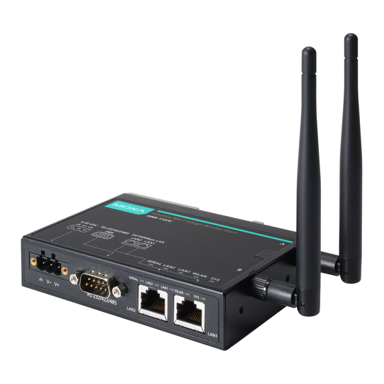
Overview The AWK-1137C industrial Wi-Fi client meets the growing need for faster data transmission speeds and wider coverage by supporting IEEE 802.11n technology with a net data rate of up to 300 Mbps. The AWK-1137C combines two adjacent 20 MHz channels into a single 40 MHz channel to deliver a potent combination of greater reliability and more bandwidth. - Page 3 Panel Layout of the AWK-1137C 1. System LEDs: SYS, WLAN, LAN1, LAN2, and SERIAL 2. LAN1: 10/100 BaseT(X) RJ45 port 3. LAN2: 10/100 BaseT(X) RJ45 port 4. RS-232/422/485 DB9 serial port 5. 3-pin terminal block (ground/-/+) 6. M3 screw holes for antenna bracket 7.
-
Page 4: Mounting Dimensions
12. Screw holes for wall-mounting Mounting Dimensions Unit = mm (inch) DIN-Rail Mounting When shipped, the metal DIN-rail mounting kit is fixed to the back panel of the AWK-1137C. Mount the AWK-1137C on the corrosion-free mounting rail that adheres to the EN 60715 standard. STEP 1: STEP 2: Insert the upper lip of the... -
Page 5: Wall Mounting (Optional)
To remove the AWK-1137C from the DIN rail, do the following: STEP 1: Pull down the latch on the DIN-rail kit with a screwdriver. STEP 2 & 3: Slightly pull the AWK-1137C forward and lift it up to remove it from the mounting rail. - Page 6 STEP 3a: Once the screws are fixed into the wall, insert the two screw heads through the large opening of the keyhole-shaped apertures, and then slide the AWK-1137C downwards, as indicated to the right. Tighten the two screws for added stability. STEP 3b: Alternatively, insert four screws directly through the AWK-1137C into the wall.
-
Page 7: Wiring Requirements
Wiring Requirements WARNING Safety First! Be sure to disconnect the power cord before installing and/or wiring your Moxa AWK-1137C. Calculate the maximum possible current in each power wire and common wire. Observe all electrical codes that dictate the maximum current allowed for each wire size. If the current goes above the maximum ratings, the wiring could overheat, causing serious damage to your equipment. - Page 8 Grounding the Moxa AWK-1137C Grounding and wire routing help limit the effects of noise due to electromagnetic interference (EMI). Run the ground connection from the ground screw to the grounding surface prior to connecting devices. ATTENTION This product is intended to be mounted to a well-grounded mounting surface, such as a metal panel.
-
Page 9: Wiring The Power Input
Wiring the Power Input The 3-contact terminal block connector on the AWK-1137C’s side panel is used for the AWK-1137C’s DC input. The top and front views of the terminal block connector are shown below: STEP 1: Insert the negative/positive DC wires into the V-/V+ terminals. -
Page 10: Communication Connections
Installing the Antenna-Locking Clamp Use the antenna-locking clamp to secure the antennas to the AWK-1137C for added stability when you install the device in a high-vibration environment. STEP 1: STEP 2: Slide the locking clamps through the Use screws to fix the clamps to the antenna ports. -
Page 11: Led Indicators
LED Indicators The front and side panel of the Moxa AWK-1137C contains several LED indicators. The function of each LED is described in the table below: Color State Description System start up complete and the system is in operation Blinking Green Beeps Device has been located by the Wireless... - Page 12 ATTENTION Use the antennas correctly: The 2.4 GHz antennas are needed when the AWK-1137C operates in IEEE 802.11b/g/n. The 5 GHz antennas are needed for operation in IEEE802.11a/n. Make sure that the antennas are installed in a safe area, which is covered by a lightning protection or surge arrest system.
- Page 13 Federal Communications Commission Interference Statement This equipment has been tested and found to comply with the limits for a Class B digital device, pursuant to part 15 of the FCC Rules. These limits are designed to provide reasonable protection against harmful interference in a residential installation.
-
Page 14: Software Setup
Software Setup This section covers the software setup for AWK models in general. How to Access the AWK Before installing the AWK device (AWK), make sure that all items in the package checklist are provided in the product box. You will also need access to a notebook computer or PC equipped with an Ethernet port. - Page 15 Point-to-Multipoint Scenario (Client Mode) Configuring the AWK as a Client Step 1: Set the operation mode of the AWK to Client mode. • Go to Wireless LAN Setup Operation Mode, select Client and click Submit to apply the change. NOTE The default operation mode for the AWK is Client.
- Page 16 Point-to-Point Scenario (Slave mode) Configuring the AWK as a Slave • Step 1: Set the operation mode of the AWK to Slave mode. Go to Wireless LAN Setup Operation Mode, set the operation mode to Slave, and then click Submit to apply the change. •...
Need help?
Do you have a question about the AirWorks AWK-1137C-EU and is the answer not in the manual?
Questions and answers