
Related Manuals for Jet J-4210


Summary of Contents for Jet J-4210
-
Page 1: Cover Page
Operating Instructions and Parts Manual Belt and Disc Sanding Machine Model J-4210 Part No. M-414550 Revision A2 03/2010 Copyright © 2010 Walter Meier (Manufacturing) Inc. -
Page 2: Warranty
Authorized Service Centers located throughout the United States can give you quick service. In most cases, any of these Walter Meier Authorized Service Centers can authorize warranty repair, assist you in obtaining parts, or perform routine maintenance and major repair on your JET® tools. For the name of an Authorized Service Center in your area call 1-800-274-6848. -
Page 3: Table Of Contents
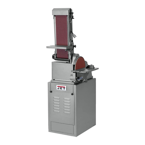
Replacement Parts ......................17 Wiring Diagram........................21 General Specifications The JETModel J-4210 Belt and Disc Sanding Machine is ideal for all shops. This versatile machine can be used to grind, sand, finish, and contour all types of parts including metal, wood, plastic, and composite materials. -
Page 4: Warnings And Safety
You — the stationary power tool user — hold the key to safety. Read and follow these simple rules for best results and full benefits from your machine. Used properly, JET machinery is among the best in design and safety. However, any machine used improperly can be rendered inefficient and unsafe. -
Page 5: Grounding Instructions
Grounding Instructions 17. Keep hands in sight and clear of all moving parts and cutting surfaces. 1. All grounded, cord-connected tools: 18. All visitors should be kept at a safe distance from In the event of a malfunction or breakdown, grounding the work area. - Page 6 able or should be used with this tool. If the tool must The temporary adapter should be used only until a be reconnected for use on a different type of electric properly grounded outlet can be installed by a quali- circuit, the reconnection should be made by qualified fied electrician.
-
Page 7: Introduction
Work Table Platen Housing Belt and Disc Sander Features Debris Duct Figures 1 and 2 depict the main features of the JET Model J-4210 Belt and Disc Sander. (Specifications On/Off Switch for the sanding machine are provided on page 3.) -
Page 8: Electrical Connection
The disc sander consists of an aluminum disc onto Installation and Setup which is installed an adhesive-backed sanding and other abrasive discs. The disc is contained within a ducted shroud. Mounting The sanding disc can be replaced by removing the It is recommended that the belt and disc sander be table and a cover over the lower portion of the disc. -
Page 9: Operating Instructions
Operation This section defines the controls and other features with which the operator should be familiar. Refer to Figures 3 and 4 for some typical sander operations. Figure 5. ON/OFF Switch Miter Gauge A miter gauge is provided with the machine and can be used on either the belt sander of disc sander work tables. -
Page 10: Disc Table
Adjusting Platen Housing Adjusting the Sander Tables Position The belt and disc sander tables can be adjusted from 0 to 45 degrees to accommodate the work piece. The sanding belt can be operated with the platen housing horizontal, vertical, or at any angle in between. -
Page 11: Maintenance
Maintenance 1. Install replacement sanding belt on drums. Position edges of sanding belt evenly on the drums. 2. Lift tensioning lever to tighten sanding belt on This section provides procedures required to main- drums. tain the belt/disc sander. The numbers in parenthe- 3. - Page 12 9. Install plate (55) and secure with four screws (56). 19. Install key in idler shaft with keyway facing up. Check for clearance between plate (55) and the Install pulley (20) on idler shaft. sanding disc. 20. Install motor V-belt (18) in outermost groove of 10.
- Page 13 Replacement of Motor WARNING: DISCONNECT ELECTRICAL POWER 6. Remove motor from base. TO THE MACHINE BEFORE PERFORMING ANY 7. Loosen set screw in pulley (18). Remove pulley. MAINTENANCE. 8. Align set screw in pulley with flat on motor shaft and install pulley. Do not tighten set screw. 1.
-
Page 14: Wiring Diagram
Correcting motor rotation in single nected to ground effectively. phase motors JET provides single phase motors in both 115 volt and 230 volt configuration. Several motor manufactures may be used by JET for motors of this type. These motors may, or may not, rotate in the correct direction -- counter-clockwise -- when connected to your single phase power source. - Page 15 be turning clockwise. If this is the case, the Connecting Power for 3-phase Motors machine can be considered wired correctly. If the motor is not turning in the correct direction, 1. Be certain the power to the branch you are take the following corrective action: connecting is off, and locked out, so power 6.
-
Page 16: Troubleshooting
Troubleshooting Fault Probable Cause Remedy Machine does not start. 1. Blown fuse or tripped 1. Determine reason for blown fuse/tripped circuit breaker. breaker (such as a short circuit or motor overload). Correct reason for fault. Replace fuse/reset breaker. 2. Motor failure. 2. -
Page 17: Replacement Parts
Replacement Parts This section provides exploded view illustrations that show the replacement parts for the JET Model J-4210 Belt/ Disc Sander. Also provided are parts listings that provide part number and description. The item numbers shown on the illustration relate the item number in the facing parts listing. - Page 18 Assembled View and Parts Listing of Stand – Model J-4210 Belt and Disc Sander Ref. Part Number Description Qty. J-5513476 Panel, Access 5513477 Knob J-5515307 Stand, Complete...
- Page 19 Exploded View – JET Model J-4210 Belt & Disc Sander...
- Page 20 Parts Listing – JET Model J-4210 Belt & Disc Sander Ref. Part Ref. Part Number Description Number Description 5513067 Screw, Set (6 X 10 MM) J-5513011 Base 5512765 Disk, Aluminum J-5513012 Bracket 5513071 Garnet Disk 10": J-5513013 Platen 80 Grit (Standard)
-
Page 21: Wiring Diagram
Wiring Diagram 4210 ELECTRICAL SCHEMATIC - 115V SWITCH 300MFD 125 VAC BLACK BLACK YELLOW BLACK WHITE WHITE GREY GREEN GREEN GROUND 4210 ELECTRICAL SCHEMATIC - 230V SWITCH 300MFD 125 VAC BLACK BLACK BLACK YELLOW WHITE WHITE GREY GREEN GREEN GROUND... - Page 22 Notes...
- Page 23 Notes...
Need help?
Do you have a question about the J-4210 and is the answer not in the manual?
Questions and answers