Table of Contents
Advertisement
Advertisement
Table of Contents

Related Manuals for Jet JOSS-S


Summary of Contents for Jet JOSS-S
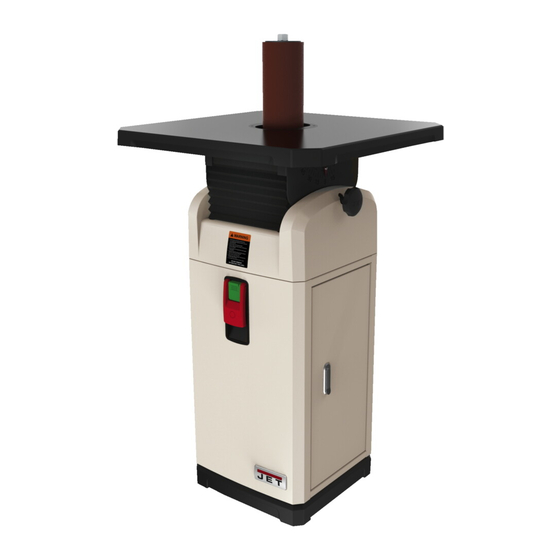
- Page 1 This .pdf document is bookmarked Operating Instructions and Parts Manual Oscillating Spindle Sander Model JOSS-S 427 New Sanford Road LaVergne, Tennessee 37086 Part No. M-723950 Ph.: 800-274-6848 Revision B 10/2015 www.jettools.com Copyright © 2015 JET...
-
Page 2: Warranty And Service
JET sells through distributors only. The specifications listed in JET printed materials and on official JET website are given as general information and are not binding. JET reserves the right to effect at any time, without prior notice, those alterations to parts, fittings, and accessory equipment which they may deem necessary for any reason ®... -
Page 3: Table Of Contents
12.2.1 JOSS-S Cabinet Assembly – Exploded View ..................18 12.2.2 JOSS-S Cabinet Assembly – Parts List ....................19 12.3.1 JOSS-S Spindle and Drum Assembly– Exploded View ..............20 12.3.2 JOSS-S Spindle and Drum Assembly– Parts List ................21 ... -
Page 4: Safety Warnings
5. Do not use this sander for other than its should be carefully checked to determine that it intended use. If used for other purposes, JET will operate properly and perform its intended disclaims any real or implied warranty and holds function. -
Page 5: About This Manual
If there are questions or comments, please contact your local supplier or JET. JET can also be reached at our web site: www.jettools.com. -
Page 6: Specifications
The specifications in this manual were current at time of publication, but because of our policy of continuous improvement, JET reserves the right to change specifications at any time and without prior notice, without incurring obligations. -
Page 7: Setup And Assembly
1/4” Spindle with sleeve – S 6.0 Setup and assembly Spindle hex nut – T Combination wrench (with magnet strip) – U Hex wrench 3mm, and magnet strip – V The sander main unit requires no assembly. Set-up involves only removing sander from pallet, and installing desired table insert and spindle/sleeve Note: All provided sanding sleeves are 100 grit. -
Page 8: Removal From Pallet
6.4 Removal from pallet To remove sander from pallet: 1. Open cabinet door and remove accessories. 2. Use ratchet wrench with extended socket to unscrew two bolts securing machine to pallet (Figure 2). 3. Move sander off pallet, with help from an assistant. -
Page 9: Installing Table Insert
Make sure spindle lock has fully disengaged from spindle before turning on sander, or damage to motor may result. remove spindle, reverse above procedure(s). 6.7 Installing table insert Tools required: cross-point screwdriver straight edge Failure to use proper table insert with corresponding spindle/drum may result in personal injury and/or damage to workpiece. -
Page 10: Wrench Storage
Note: Leveling one insert is sufficient as all 7.0 Electrical connections inserts are same thickness. The JOSS-S sander is rated at 115/230V power, and is pre-wired for 115 volt. The sander comes with a plug designed for use on a circuit with a grounded outlet that looks like the one pictured in A, Figure 8. -
Page 11: Voltage Conversion
The temporary adapter should be used only until a Ampere Total length of Volts properly grounded outlet can be installed by a Rating cord in feet qualified electrician. This adapter is not permitted in Canada. The green-colored rigid ear, lug, and the More More like, extending from the adapter must be connected... -
Page 12: Operations
8.2 Table tilt for bevel sanding 5. If needed, loosen pointer (E) and align it with zero degree mark. Refer to Figures 11 and 12. 6. Tilt table to 45-degrees and check accuracy of 1. Loosen both knobs Figure 45-degree stop screw (F). Adjust as needed. counterclockwise. -
Page 13: Safety Switch
10.2 Gearbox lubrication 9. Sanding sleeve life may be prolonged by reversing it on the spindle to make use of Periodically check oil level at the sight glass (D, opposite end. Figure 15) – oil should be mid-level in the glass. Use good quality SAE 90 gear oil. -
Page 14: Troubleshooting Joss-S Spindle Sander
11.0 Troubleshooting JOSS-S Spindle Sander Symptom Possible Cause Correction Sander will not start. Sander unplugged from wall or motor. Check all plug connections. Fuse blown, or circuit breaker tripped Replace fuse, or reset circuit breaker. in service panel. Cord damaged. -
Page 15: Joss-S Table Assembly - Exploded View
12.1.1 JOSS-S Table Assembly – Exploded View... -
Page 16: Joss-S Table Assembly - Parts List
1 ....SBR30M-62....Spring Pin ..............5*20L......1 2 ....JOSS-S-102 ....Table ......................1 3 ....JOSS-S-103 ....Phillips Flat Head Screw .......... M6*1.0P*15L ....4 4 ....JOSS-S-104 ....Hook-and-Loop Fastener (Male) Set ............. 1 5 ....JOSS-S-105 ....Rubber Shield Holder ..................1 6 .... - Page 17 70 ....JOSS-S-170 ....Socket Head Cap Screw.......... M3*0.5P*14L ....2 71 ....JOSS-S-171 ....Key......................... 1 72 ....JOSS-S-172 ....Phillips Flat Head Screw .......... M5*0.8P*10L ....3 73 ....JOSS-S-173 ....Special Nut ....................1 74 ....JOSS-S-174 ....Worm Shaft ....................1 75 ....
-
Page 18: Joss-S Cabinet Assembly - Exploded View
12.2.1 JOSS-S Cabinet Assembly – Exploded View... -
Page 19: Joss-S Cabinet Assembly - Parts List
35 ....JOSS-S-235 ....Table Insert (only for 3/8” spindle at 90 deg.) ..........1 36 ....JOSS-S-236 ....Table Insert (only for 2” Rubber Drum at 90 deg.) ......... 1 37 ....JOSS-S-237 ....Table Insert (only for 4” Rubber Drum at 90 deg.) ......... 1 38 .... -
Page 20: Joss-S Spindle And Drum Assembly- Exploded View
12.3.1 JOSS-S Spindle and Drum Assembly– Exploded View... -
Page 21: Joss-S Spindle And Drum Assembly- Parts List
....575894 ....Sanding Sleeve (150 Grit) – 4 pack ......1/4” x 6” ......13 ....JOSS-S-313 ..Collar (for 1/4” Spindle Assembly) ..............1 14 ....JOSS-S-314 ..Spindle Assembly (incl. #6, 7, 8, 9, 15, 17 & 100G sleeve)….3/8” ...... 1 15 ....JOSS-S-315 ..Spindle ................3/8” ........ 1 16 .... - Page 22 ....575949 ....Sanding Sleeve (150 Grit) – 4 pack ......3” x 9” ......43 ....JOSS-S-343 ..Washer ................. 3” ........2 44 ....JOSS-S-344 ..Drum Assembly (incl.#29, 45, 47 & 100G sleeve) ..4” ........1 45 ....JOSS-S-345 ..Rubber Drum ..............4” ........1 46 ....
-
Page 23: Electrical Connections - Joss-S Spindle Sander
13.0 Electrical Connections – JOSS-S Spindle Sander... - Page 24 427 New Sanford Road LaVergne, Tennessee 37086 Phone: 800-274-6848 www.jettools.com...
Need help?
Do you have a question about the JOSS-S and is the answer not in the manual?
Questions and answers