Table of Contents
Advertisement
Quick Links
This .pdf document is bookmarked
Operating Instructions and Parts Manual
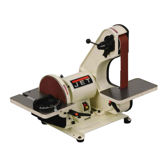
Belt and Disc Sander
Model J-41002
2" x 42" Belt and 8" Disc Sander
–
WALTER MEIER (Manufacturing) Inc.
427 New Sanford Road
LaVergne, Tennessee 37086
Part No. M-577004
Ph.: 800-274-6848
Revision B 05/2011
www.waltermeier.com
Copyright © 2011 Walter Meier (Manufacturing) Inc.
Advertisement
Table of Contents

Related Manuals for Jet J-41002


Summary of Contents for Jet J-41002
- Page 1 This .pdf document is bookmarked Operating Instructions and Parts Manual Belt and Disc Sander Model J-41002 2" x 42" Belt and 8" Disc Sander – WALTER MEIER (Manufacturing) Inc. 427 New Sanford Road LaVergne, Tennessee 37086 Part No. M-577004 Ph.: 800-274-6848 Revision B 05/2011 www.waltermeier.com...
-
Page 2: Warranty And Service
Walter Meier is consistently adding new products to the line. For complete, up-to-date product information, check with your local Walter Meier distributor, or visit waltermeier.com. WARRANTY JET products carry a limited warranty which varies in duration based upon the product (MW = Metalworking, WW = Woodworking). WHAT IS COVERED? This warranty covers any defects in workmanship or materials subject to the exceptions stated below. -
Page 3: Table Of Contents
Table of Contents Warranty and Service..........................2 Table of Contents ..........................3 Warning .............................4 Introduction ............................6 Specifications .............................6 Features and Terminology ........................7 Unpacking ............................8 Contents of the Shipping Container ....................8 Assembly ............................9 Installing Belt Table .........................9 Installing Dust Chute ........................9 Installing Disc Table ........................10 Installing Miter Gauge ........................ -
Page 4: Warning
Warning 1. Read and understand the entire owner’s manual before attempting assembly or operation. 2. Read and understand the warnings posted on the machine and in this manual. Failure to comply with all of these warnings may cause serious injury. 3. - Page 5 21. Make your workshop child proof with padlocks, master switches or by removing starter keys. 22. Give your work undivided attention. Looking around, carrying on a conversation and “horse-play” are careless acts that can result in serious injury. 23. Maintain a balanced stance at all times so that you do not fall or lean against the abrasives or other moving parts.
-
Page 6: Introduction
Introduction This manual is provided by Walter Meier (Manufacturing) Inc., covering the safe operation and maintenance procedures for a JET 2x42x8 Belt and Disc Sander. This manual contains instructions on installation, safety precautions, general operating procedures, maintenance instructions and parts breakdown. -
Page 7: Features And Terminology
Features and Terminology... -
Page 8: Unpacking
Contents of the Shipping Container Unpacking Belt and Disc Sander Open shipping container and check for shipping Belt Table damage. Report any damage immediately to Disc Table with trunnions your distributor and shipping agent. Do not discard any shipping material until the sander is Miter Gauge assembled and running properly. -
Page 9: Assembly
Assembly Tools needed for assembly: • 10mm open-end wrench • Cross-point (Phillips) screwdriver • Combination square, similar angle measuring device. Sander must be unplugged from power source during assembly. Remove the protective coating from the surfaces of the sander and from any loose parts. This coating may be removed with a soft cloth moistened with kerosene (do not use acetone, gasoline or lacquer thinner for this purpose). -
Page 10: Installing Disc Table
Installing Disc Table 1. Position the disc table at an angle, as shown in Figure 3, and slide the table on so that the trunnion slots fit over the raised tracks on the disc guard. 2. Install a flat washer onto each of the two remaining handles. -
Page 11: Grounding Instructions
A temporary adapter, like the adapter in Figure Grounding Instructions 8, may be used to connect this plug to a two- pole receptacle, as shown in Figure 8, if a properly grounded outlet is not available. The This machine must temporary adapter should only be used until a grounded while in use to protect the operator properly grounded outlet can be installed by a... -
Page 12: Adjustments
Adjustments Tilting the Belt Table The belt table tilts from zero (horizontal) down to 45°. 1. Loosen the handle and adjust the table into desired position. 2. Check angle with machinist’s protractor or similar measuring device that has the required angle. Figure 10 shows a square being used to confirm the zero, or horizontal, position. -
Page 13: Use Of The Miter Gauge
Use of the Miter Gauge The miter gauge is used to sand accurate angles on workpieces. When using the miter gauge on the horizontal table position, you can sand a single angle. By tilting the disc table and using the miter gauge in combination with the table tilted, it is possible to sand compound angles as well. -
Page 14: Abrasive Belt Replacement
Abrasive Belt Replacement 1. Unplug the Sander from the power source. 2. Unscrew and remove the two knobs on the belt cover. 3. Remove the belt cover. 4. Rotate the tension handle (Figure 6) to loosen the belt, and remove the old belt from around the wheels. -
Page 15: Abrasive Disc Replacement
Abrasive Disc Replacement 1. Unplug the sander from the power source. 2. Remove the dust cover and the disc table. To remove the disc table, remove the handles then tilt the disc table upward while pulling it away from the disc. 3. -
Page 16: Operation
Operation This sander is intended for dry sanding of metals. Do not use lubricants. Do not sand or polish magnesium; it may create a fire hazard. Also, do not sand very small or very thin workpieces that cannot be safely controlled. Starting and Stopping the Sander The on/off switch is located on the side of the motor housing. - Page 17 The following are just some of the many operations that can be performed with your JET Sander. • Sharpening a wood chisel on the sanding belt using a block of wood.
-
Page 18: Maintenance
Maintenance Check all fasteners for tightness. Before performing maintenance on the machine, disconnect it Inspect the power cord; if worn, cut, or damaged from the electrical supply by pulling out the in any way, have it replaced immediately. plug or switching off the main switch. Failure to comply may cause serious injury. -
Page 19: Troubleshooting
Troubleshooting Trouble Probable Cause Remedy Not connected to power source. Connect to power source. Determine reason for blown fuse/ tripped breaker (such as short circuit Branch circuit fuse is blown or the or motor overload). Correct reason for circuit breaker is tripped. fault. -
Page 20: Assembly Drawing
Assembly Drawing... -
Page 21: Parts List
20 .... 41002-20....Line Cord ................... 1 22 .... 41002-22....Strain Relief Bushing ................1 23 .... 41002-23....Self Tapping Screw ...........10-24X3/8” ....2 24 .... J-41002-24 ....Motor Housing Base ................1 24A..J-41002-24A1 ..Motor Assembly ..........115V, 1Ph ....1 25 .... 41002-25....Switch with Key .................. 1 26 .... - Page 22 Parts List 57 .... TS-1505021 ....Socket Head Cap Screw ........M10x20 ...... 2 58 .... J-41002-58 ....Belt Housing ..................1 59 .... TS-0680031 ....Flat Washer............5/16” ......4 60 .... TS-0570011 ....Hex Nut............1/4”-20 ....... 1 61 .... TS-1490021 ....Hex Cap Screw ..........M8x16......2 62 ....
- Page 23 Notes...
- Page 24 WALTER MEIER (Manufacturing) Inc. 427 New Sanford Road LaVergne, Tennessee 37086 Ph.: 800-274-6848 www.waltermeier.com...
Need help?
Do you have a question about the J-41002 and is the answer not in the manual?
Questions and answers