Table of Contents
Advertisement
Quick Links
Advertisement
Table of Contents

Related Manuals for Jet J-4210


Summary of Contents for Jet J-4210
- Page 1 This .pdf document is bookmarked Operating Instructions and Parts Manual Belt and Disc Sanding Machine Model J-4210 427 New Sanford Road LaVergne, Tennessee 37086 Part No. M-414550 Ph.: 800-274-6848 Revision C 10/2018 www.jettools.com Copyright © 2014 JET...
-
Page 2: Important Safety Instructions
17. Keep hands in sight and clear of all moving parts - Never modify the machine without consulting JET. and cutting surfaces. 1.1 General Machinery Warnings 18. All visitors should be kept at a safe distance from the work area. -
Page 3: Safety Requirements For Abrasive Sanding Machines
1.3 Safety Requirements for Abrasive discs must be stored in a controlled Abrasive Sanding Machines environment area. Relative humidity should be 35% to 50% and the temperature should be Abrasive sanding can be hazardous to operators between 60 and 80 degrees Farenheit. Failure and bystanders. -
Page 4: Table Of Contents
12.0 Troubleshooting J-4210 Belt-Disc Sander ....................12 13.0 Replacement Parts ............................. 12 13.1.1 J-4210 Belt & Disc Sander – Exploded View ..................13 13.1.2 J-4210 Belt & Disc Sander – Parts List ....................14 13.2.1 J-4210 Stand – Exploded View ......................16 13.2.2 J-4210 Stand –... -
Page 5: About This Manual
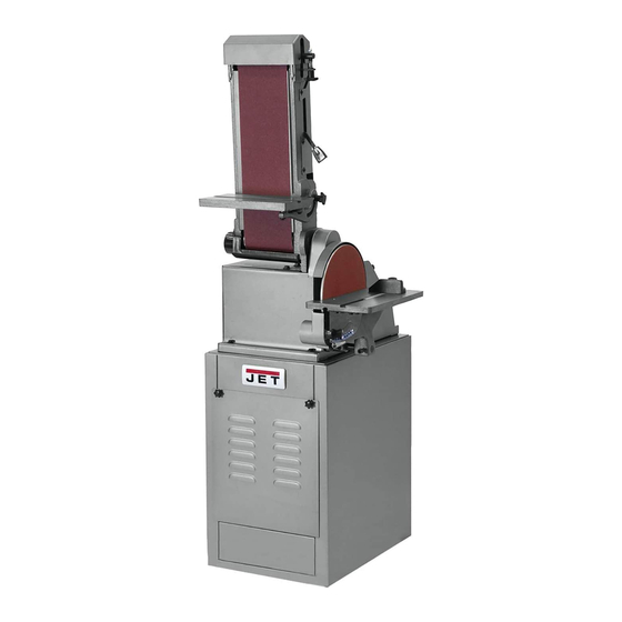
4.0 About the J-4210 Sander The JET Model J-4210 Belt and Disc Sanding Machine is ideal for all shops. This versatile machine can be used to grind, sand, finish, and contour all types of parts including metal, wood, plastic, and composite materials. -
Page 6: Specifications
Subject to local/national electrical codes. The specifications in this manual were current at time of publication, but because of our policy of continuous improvement, JET reserves the right to change specifications at any time and without prior notice, without incurring obligations. -
Page 7: Setup And Assembly
8.0 Electrical connections like, extending from the adapter must be connected to a permanent ground such as a properly grounded The J-4210 Belt/Disc Sander is rated at 115/230V outlet box. power, and is pre-wired for 115 volt. 3. Grounded, cord-connected tools intended for use... -
Page 8: Voltage Conversion
8.2 Voltage conversion Move platen housing to desired position. When platen housing is to be placed in horizontal Disconnect machine from power source. position, lower platen housing onto stop screw (28) on machine base. To switch the incoming power leads for 230 volt operation, follow wiring diagram on inside cover of If the stop requires adjustment, loosen jam nut motor junction box. -
Page 9: Operation
10.2 Controls 9.3.2 Belt table To change belt table angle, loosen clamping The on/off switch is located on the side of the knob on right side of platen housing (refer to machine base. It has a safety key to prevent Figure 6). -
Page 10: Replacing Sanding Disc
11.5 Replacing V-belts Lift tensioning lever to tighten sanding belt on drums. Disconnect electrical power. Install guard (75) and secure with screw (76). Remove sanding belt table. 10. Install guard (96) and secure with eight screws Remove sanding disc table. (97). -
Page 11: Replacing Motor
11.6 Replacing motor NOTE: Because of the weight of the belt housing, a second person should hold belt Disconnect electrical power. housing in position while installing pulley (10). Remove four screws from base. With 23. Hold belt housing in position in bracket (3). Start assistance of a second person, lift base from two screws (13) in threaded holes in platen. -
Page 12: Troubleshooting J-4210 Belt-Disc Sander
Non-proprietary parts, such as fasteners, can be found at local hardware stores, or may be ordered from JET. Some parts are shown for reference only, and may not be available individually. -
Page 13: J-4210 Belt & Disc Sander - Exploded View
13.1.1 J-4210 Belt & Disc Sander – Exploded View... -
Page 14: J-4210 Belt & Disc Sander - Parts List
13.1.2 J-4210 Belt & Disc Sander – Parts List Index No Part No Description Size 2 ....J-5513011G ....Base....................... 1 3 ....J-5513012G ....Bracket......................1 4 ....J-5513013G ....Platen......................1 5 ....5513014 ....Drive Drum..................... 1 6 .... - Page 15 Index No Part No Description Size 59 ....5513071 ....Garnet Disc .............. 10", 80 Grit ....1 ....5513073 ....Garnet Disc .............. 10", 100 Grit ....1 ....5513075 ....Garnet Disc .............. 10", 120 Grit ....1 60 ....
-
Page 16: J-4210 Stand - Exploded View
13.2.1 J-4210 Stand – Exploded View 13.2.2 J-4210 Stand – Parts List Index No Part No Description Size 1 ....J-5513476G ....Access Panel ....................1 2 ....5513477 ....Knob ......................2 3 ....414549 ...... Complete Stand Assembly ................1... -
Page 17: Electrical Connections For J-4210
14.0 Electrical Connections for J-4210... -
Page 18: Warranty And Service
JET sells through distributors only. The specifications listed in JET printed materials and on official JET website are given as general information and are not binding. JET reserves the right to effect at any time, without prior notice, those alterations to parts, fittings, and accessory equipment which they may deem necessary for any reason ®... - Page 19 427 New Sanford Road LaVergne, Tennessee 37086 Phone: 800-274-6848 www.jettools.com...
Need help?
Do you have a question about the J-4210 and is the answer not in the manual?
Questions and answers