Table of Contents
Advertisement
Quick Links
Advertisement
Table of Contents

Subscribe to Our Youtube Channel
Related Manuals for Jet J-4002


Summary of Contents for Jet J-4002
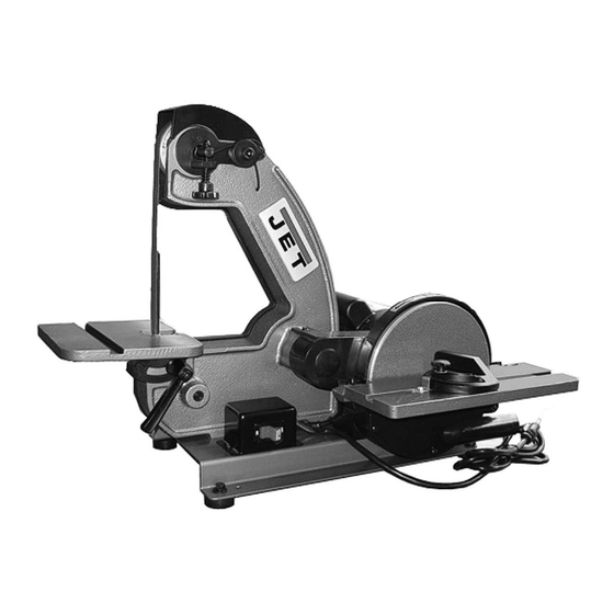
- Page 1 This .pdf document is bookmarked Operating Instructions and Parts Manual Belt and Disc Sander (1x42” belt, 8” disc) Model J-4002 427 New Sanford Road Part No. M-577003 LaVergne, Tennessee 37086 Revision B 04/2015 Ph.: 800-274-6848 (ECR TW0134) www.jettools.com Copyright © 2015 JET...
-
Page 2: Warranty And Service
JET sells through distributors only. The specifications listed in JET printed materials and on official JET website are given as general information and are not binding. JET reserves the right to effect at any time, without prior notice, those alterations to parts, fittings, and accessory equipment which they may deem necessary for any reason ®... -
Page 3: Table Of Contents
12.0 Typical operations ............................12 13.0 Replacement Parts ............................. 14 13.1.1 J-4002 Belt Parts – Exploded View ..................... 14 13.1.2 J-4002 Belt Parts – Parts List ......................14 13.2.1 J-4002 Disc Parts – Exploded View ....................16 ... -
Page 4: Safety Warnings
Read and follow these simple rules for best results operate the machine. and full benefits from your machine. Used properly, JET machinery is among the best in design and 12. Never brush chips away while the machine is safety. However, any machine used improperly can in operation. -
Page 5: General Electrical Cautions
• 15. Use the right tool. Don’t force a tool or Arsenic and chromium from chemically treated attachment to do a job for which it was not lumber. designed. Your risk of exposure varies, depending on how 16. Use only recommended accessories and often you do this type of work. -
Page 6: About This Manual
If there are questions or comments, please contact your local supplier or JET. JET can also be reached at our web site: www.jettools.com. -
Page 7: Unpacking
5. Check for 1/16-inch clearance between edge For your own safety, do not of table and face of disc. Adjust clearance if connect sander to power source until the required (see sect. 10.4.2). machine is completely assembled and you have read and understood the entire Operating 7.2 Assembling belt sander table Instructions and Parts Manual. -
Page 8: Setup
grounding plug. The plug must be plugged into a 8.0 Setup matching outlet that is properly installed and grounded in accordance with all local codes and 8.1 Fastening sander to supporting ordinances. surface Do not modify the plug provided—if it will not fit have a new outlet installed by a qualified During operation, the sander may have a tendency electrician. -
Page 9: Adjustments
screw. Be sure to reinstall platen before performing 10.0 Adjustments operations where support of the belt is required. 10.3 Belt table adjustments Disconnect machine from power source before making any adjustments. The belt sander table can be tilted or moved in or accommodate operation being... -
Page 10: Disc Table Adjustments
needed to establish a 1/16-inch gap. When gap is established, tighten setscrew. Figure 13: Setting belt table to 45-degrees 10.4 Disc table adjustments 10.4.1 Adjusting disc table angle Figure 16: Removal of sanding disc To avoid trapping the work or 10.5 Changing abrasive belts fingers between table and sanding disc, the 1. -
Page 11: Changing Abrasive Discs
10.6 Changing abrasive discs 1. Disconnect machine from power source. 2. Remove screws and nuts from sanding disc table. Remove disc table. 3. Remove lower disc guard (see Figure 19). Figure 22: Disc installation 9. Tighten setscrew in hub of disc plate. 10. -
Page 12: Operating Instructions
The following are just some of the many operations 11.1 Starting and stopping sander that can be performed with your JET Sander: Sharpening a wood chisel on the sanding belt The on/off switch (see Figure 8) is mounted in a using a block of wood. - Page 13 Figure 29: Sanding in tight areas Inside curves can be sanded on the upper sanding belt idler wheel (see Figure 30). The upper cover Figure 26: Sanding aluminum can either be hinged back or removed. Sanding outside curves on the belt unit with the platen removed (see Figure 27).
-
Page 14: Replacement Parts
800-274-6848 Monday through Friday (see our website for business hours, www.jettools.com). Having the Model Number and Serial Number of your machine available when you call will allow us to serve you quickly and accurately. 13.1.1 J-4002 Belt Parts – Exploded View 13.1.2 J-4002 Belt Parts – Parts List Index No Part No... - Page 15 71 ....5640451 ....Lock Washer ............M10 ....... 2 72 ....5640441 ....Hex Socket Head Screw .......... M10x20 ......2 103 .... 5640561 ....Rotation Label....................1 104 .... JET-113..... JET Logo (not shown)..........113x47mm ....1...
-
Page 16: J-4002 Disc Parts - Exploded View
13.2.1 J-4002 Disc Parts – Exploded View... -
Page 17: J-4002 Disc Parts - Parts List
13.2.2 J-4002 Disc Parts – Parts List Index No Part No Description Size 53 ....5640711 ....Hex Socket Head Screw .......... M5x12 ......1 54 ....5640721 ....Drive Pulley....................1 55 ....5640731 ....Key......................... 1 56 .... - Page 18 This page intentionally left blank.
- Page 19 This page intentionally left blank.
- Page 20 427 New Sanford Road LaVergne, Tennessee 37086 Phone: 800-274-6848 www.jetttools.com...
Need help?
Do you have a question about the J-4002 and is the answer not in the manual?
Questions and answers